Download to read offline


![Dual Feed Microstrip Patch Antenna for Wlan Applications
DOI: 10.9790/2834-10510105 www.iosrjournals.org 5 | Page
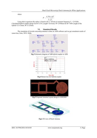
Fig.11 Effective Area of Microstrip antenna
Fig.12 Radiated power of Microstrip antenna
Table I: Simulated Circular Polarized Microstrip Patch Antenna Results
Specifications Observation
Frequency(GHz) 2.404
Return Loss (dB) -28.003
Power radiated(W) 2.1x10⁴
Effective angle 1.57615
Gain 6.36836
Directivity 9.01612
Efficiency 55%
Maximum intensity 1.26896x10⁴
HPBW(dB) 85.1496
VII. Conclusion
There are various types of microstrip antennas able to excite a circular polarization. In this paper, dual
fed circular polarization microstrip antenna was chosen. The microstrip antenna is design to operate at 2.404
GHz frequency. The dual fed circular polarization microstrip antenna is successfully implemented and
fabricated. The microstrip antenna resonates at 2.404 GHz and gives better return loss, which is -28.003 dB. The
proposed antenna given better value because only 0.47 % power is reflected and 99.53 % power is transmitted.
The VSWR of the microstrip antenna is 1.2:1, which shows that the level of mismatched for the microstrip
antenna is not very high. The bandwidth of this microstrip antenna is better, which is 17.04 % and the maximum
radiation occurs at -40° with gain of 6.36dB. The Microstrip antenna is said to be circular if the axial ratio is 0
dB. From the calculation of axial ratio, most of the angles give 0 dB value, thus prove that the microstrip
antenna polarize circularly.
References
[1] Pramendra Tilanthe, P. C. Sharma, and T. K. Bandopadhyay, “Gain Enhancement of Circular Microstrip Antenna for Personal
Communication Systems,” IACSIT International Journal of Engineering and Technology, Vol.3, No.2, April 2011.
[2] J. -Y. Park, C. Caloz, Y. Qian, and T. Itoh, “A compact circularly polarized subdivided microstrip patch antenna,” IEEE Microwave
Wireless Component Letters, vol. 12, pp. 18-19, Jan 2002.
[3] S. Zhang, C. Zhu, J. K. O. Sin, and P. K. T. Mok, “A novel ultrathin elevated channel low-temperature poly-Si TFT,” IEEE
Electron Device Lett., vol. 20, pp. 569–571, Nov. 1999.
[4] D. A. El Aziz and R. Hamad, “ Wideband Circular Microstrip Antenna For Wireless Communication Systems,” Radio Science
Conference, pp. 1-8, March 2007.
[5] Constantine. A. Balanis, “ Antenna Theory Analysis and Design,”2nd ed., John Wiely and Sons,Inc., 1997.
[6] N. A. Zakaria, A. A. Sulaiman., and M. A. A. Latip, “Design of a Circular Microstrip Antenna,”IEEE International RF and
Microwave Proceedings, pp. 289-292, December 2008.
[7] Jieh-Sen Kuo and Gui-Bin Hsieh, “Gain Enhancement of a Circularly Polarized Equilateral-Triangular Microstrip Antenna with a
Slotted Ground Plane,” IEEE Transactions on Antennas and Propagation, vol. 51, no. 7, July 2003.](https://image.slidesharecdn.com/a010510105-160805101313/85/A010510105-5-320.jpg)

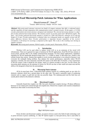
This document describes the design and simulation of a dual-fed circularly polarized microstrip patch antenna for WLAN applications at 2.4 GHz. A circular patch antenna with a diameter of 30 mm is designed on an FR4 substrate with a dielectric constant of 4.6 and thickness of 1.6 mm. Circular polarization is achieved by feeding the patch from two points with a 90 degree phase difference using a 3dB hybrid coupler. The antenna is simulated using ADS software. Simulation results show the antenna resonates at 2.404 GHz with a return loss of -28.003 dB and gain of 6.368 dB. The antenna provides circular polarization as required for WLAN applications.