Downloaded 40 times


![Continuous casting of Copper-Based Alloys and Precious Metals
used, and as would be expected a 'thermally turbulent' zone is created, resulting in
poor heat transfer from the inner surfaces of the rods. In horizontal casting the
resulting oval-shaped isotherm exaggerates defects such as hot tearing, and in tin
bronzes inverse segregation tends to be more pronounced on the inner surfaces.
Jacket-cooled dies are limited to slower casting speeds.
In probe-cooled dies heat transfer is predominantly axial. The design is very
versatile and now used extensively on small-section rod, tube and strip. From the
heat transfer aspect it is not highly efficient and it is limited in casting speed. Refer
to Section 1.6.3 for further details.
2.2 OVERALL ENERGY BALANCE FROM
PROPERTIES OF MATERIALS
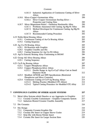
The thermal efficiency of the operation can be assessed by determining the
enthalpies of the liquid and solid metal ingot, and the corresponding water coolant,
using these in a simple, heat balance equation. The total quantity of heat which has
to be removed from the liquid/solid metal, within the die, is composed of superheat,
latent heat, specific heats and heat contained in the solid metal due to its
temperature. There may be a certain amount of heat due to solid-phase transforma-
tions but this would be small and can be ignored.
The overall heat balance, within the die and cooler assembly, can be represented
by the heat passing in the direction of metal flow and the coolant passing in the
opposite direction. The total enthalpy of the metal can be balanced against that of
the coolant by applying the equations outlined below.
The total heat derived from the liquid/solid ingot is:
SHM SmM
---at = ---at [CI(Oc - Om) + Lc + Cs(Om - Ox)] (2.1)
The quantity SmM/St represents the weight of metal cast per unit time and is
referred to as the 'casting rate'. It is generally more convenient to use the term
'casting speed' V, which is the linear velocity of the cast ingot. This is correlated to
the casting rate by:
SmM
--=A·p·V
St
(2.2)
The heat extracted from the metal by the coolant is:
SHW SmW
-- == -- X PW(OW2 - OWl)
St St
(2.3)
pW is unity:. 8~ = wi> (OW2 - OWl)
44](https://image.slidesharecdn.com/apracticalapproachtocontinuouscasting-robertwilson-230430074453-bf653c23/85/A-practical-approach-to-continuous-casting-60-320.jpg)

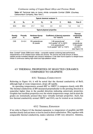
![Continuous casting of Copper-Based Alloys and Precious Metals
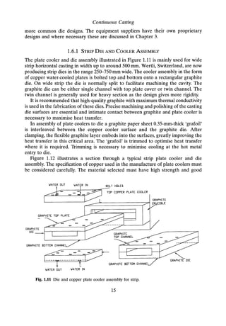
Table 2.3 Heat balance on continuous cast sterling silver strip.
Material - sterling silver Ag 92.5 wt°/o - Cu 7.5 wt°/o
Heat balance equations:
8HM 8mM
8t = Tt [C/(8c - 8m) + Lc + Cs(8m - 8x)]
8HW
:'M = wt»: (OW2 - 8W1)
(2.1)
(2.3)
Strip
120 mm width x 10 mm thick
Casting speed
Density at 20°C
Density - liquid
Latent heat (Lc)
Specific heat liquid (C~
Specific heat solid (Cs)
Water in - temperature
Water out - temperature
Water flow (wf)
Melt temperature (OC)
Mean liquidus/solidus temperature (8m)
Metal exit temperature (Ox)
Cross section area (A)
8HM
8t
8HW
8t
8HM/8HW
at MX100
120 mm/min
10.366 g/cm3
9.210 g/cm3
27.445 cal/gm
0.070 cal/gm
0.059 cal/gm
12°C
25°C
11.75 litres/min
1025°C
845°C
90°C
12 ern"
2100 cal/sec - 8792 joule
2546 cal/sec - 10,660 joule
82.5%
46](https://image.slidesharecdn.com/apracticalapproachtocontinuouscasting-robertwilson-230430074453-bf653c23/85/A-practical-approach-to-continuous-casting-62-320.jpg)
![Heat Transfer
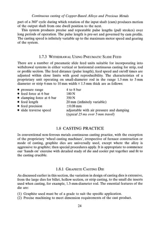
Table 2.4 Heat balance on OFHC copper rod.
Heat balance equations:
8HM 8mM
M= Bt[C/(Oc - Om) + Lc + Cs(Om - Ox)]
8HW
:.-- = wt x (OW2 - OW,)
at
(2.1)
(2.3)
Material - OFHC copper
Cu 99.99+%
Rod
Casting speed
Density at 20°C
Density - liquid
Latent heat (Lc)
Specific heat liquid (C~
Specific heat solid (Cs)
Water in - temperature
Water out - temperature
Water flow through cooler
Melt temperature (8C)
Mean liquidus/solidus temperature (Om)
Metal exit temperature (Ox)
Cross section area (A)
Mass g/sec
12 mm diameter
1.50 metres/min
8.96 g/cm3
7.95 g/cm3
49 cal/gm
0.118 cal/gm
0.092 cal/gm
16°C
33°C
15 litres/min
1220°C
1083°C
105°C
1.13 ern"
25.333
aHM
at
aHW
8t
SHM/aHW
st BtX100
3930 cal/sec - 16,454 joule
4250 cal/sec - 17,794 joule
92%
47](https://image.slidesharecdn.com/apracticalapproachtocontinuouscasting-robertwilson-230430074453-bf653c23/85/A-practical-approach-to-continuous-casting-63-320.jpg)
![Continuous casting of Copper-Based Alloys and Precious Metals
Table 2.5 Heat balance on upcast copper-bismuth alloy LG equivalent
(for casting data refer to Section 5.12.3).
Heat balance equations:
aHM amM
8t = 8t[C/(Oc - Om) + Lc + Cs(Om - Ox)]
aHW
:.-- = wt »: (OW2 - OW1)
at
(2.1)
(2.3)
Material - copper-bismuth alloy
C89844 - LG2 equivalent
Nominal analyses:
Cu% 82 - Sn%, 4 - Bi%, 3 - Ni%, 2 - Zn% 9
Tube
Casting speed
Density at 20°C
Density - liquid
Latent heat (Lc)
Specific heat liquid (C~
Specific heat solid (Cs)
Water in - temperature
Water out - temperature
Water flow through cooler
Melt temperature (BC)
Mean liquidus/solidus temperature (Om)
Metal exit temperature (Ox)
Cross section area (A)
Mass g/sec
0021 mm 10 13 mm
Casting speed 630 mm/min
8.70 g/cm3
7.81 q/crn"
39.05 cal/gm
0.107 cal/gm
0.085 cal/gm
22°C
33°C
17 litres/min
1030°C
880°C
100°C
2.136 ern"
19.515
8HM
at
8HW
at
8HM/8HW
aT atX
100
2363 cal/sec - 9893 joule
3117 cal/sec - 13,050 joule
75%
48](https://image.slidesharecdn.com/apracticalapproachtocontinuouscasting-robertwilson-230430074453-bf653c23/85/A-practical-approach-to-continuous-casting-64-320.jpg)
![Heat Transfer
Table 2.6 Heat balance on horizontal on palladium-silver alloy strip
(for casting data refer to Section 5.12.3).
Heat balance equations:
8HM 8mM
at = 5t[C/(8c - Om) + Lc + Cs(Om - Ox)]
8HW
:.-- = wi »: (OW2 - OW1)
8t
(2.1)
(2.3)
Material - palladium-silver alloy Nominal analyses 0/0:
Pd 55 - Ag 35 - Sn 8 - others rem.
Strip
Casting speed
Density at 20°C
Density - liquid
Latent heat (Lc)
Specific heat liquid (C~
Specific heat solid (Cs)
Water in - temperature
Water out - temperature
Water flow through cooler
Melt temperature (OC)
Mean liquidus/solidus temperature (Om)
Metal exit temperature (ex)
Cross section area (A)
Mass g/sec
10 mm x 3 mm thick
Casting speed 450 mm/min
10.88 g/cm3
9.76 g/cm3
39.14 cal/gm
0.070 cal/gm
0.057 cal/gm
18°C
32°C
3.0 litres/min
1350°C
1225°C
90°C
0.300 ern"
2.455
8HM
8t
8HW
8t
8HM/8HW
aT 5t
X100
277 cal/sec - 1159 joule
700 cal/sec - 2931 joule
40%
49](https://image.slidesharecdn.com/apracticalapproachtocontinuouscasting-robertwilson-230430074453-bf653c23/85/A-practical-approach-to-continuous-casting-65-320.jpg)


![Continuous casting of Copper-Based Alloys and Precious Metals
LC)
~
Q)
:0
~
o
..•...•
~
Q)
"t-
Q)
a:
-t
tU
s:
U
en
c
o
~
.2
0..
a.
tU
I
0>
c
~tU
U
en
~
o
~
c
~c
o
o
~
o
"t-
tJ)
~
;;:
~
C1)
c.
c.
o
o
::Jo..
OI
o
CiS
c
N
::J
o
z
c
~::J
o
z
(])
~ "
::J
o
.c
co..'E
cg~~.
o::J(J)
o ::J
o
.c
0..
c
N
::J
o
•
•
O>(])
~.§
"C
0..
0>
-c
O>cn
0>'£ >. A
~~gw
..a «1
•
84](https://image.slidesharecdn.com/apracticalapproachtocontinuouscasting-robertwilson-230430074453-bf653c23/85/A-practical-approach-to-continuous-casting-100-320.jpg)


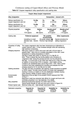
![Continuous Casting of Copper-Based Alloys
[6]
[1
[1] steel furnace shell
[2] fixed top plate
[3] movable steel top plate
[4] die cooler assembly
[5] solenoid/stopper
[6] pressure loader
[7] terminal connections &
graphite heating elements
(8] top crucible (melt)
(9] bottom crucible (casting)
[10] freeze/drain plug
[11] dump box
FLOATING GRAPHITE BAFFLE
IN TOP CRUCIBLE
RWD9425C
Fig. 5.7 Pressure upcast furnace assembly. Patents UK and USA.31 Courtesy
Rautomead International, Dundee.
5.5.1 DETAILS OF THE PLANT
As shown in furnace layout Figure 5.7, the twin graphite crucible assembly,
contained within a steel pressure-sealed shell, consists of an upper melt chamber and
a lower casting chamber with integral feed ducts to die recesses. The feed ducts
draining from the base of the crucible are designed to enable more or less complete
cast-out of the melt. A duct is provided at the base of the crucible with water-cooled
freeze plug to drain any surplus metal from the system at the end of a run or to
'dump' the charge if required.
The melt crucible [8] is charged via the pressure loader [6]. This is a twin-
chamber unit with pressure seal allowing intermittent charging of cold metal
without interruption of the pressure-casting programme. The melt is mixed and
homogenised in this crucible, the mixing assisted by means of a floating graphite
baffle. Effective deoxidation of the melt is completed in the top crucible prior to
discharge to the lower casting crucible. The melt is transferred to the bottom casting
crucible [9] by activating a stopper [5]. Under pressure, the melt is raised into the
casting die [4] via integral ducts in the crucible. The furnace is operated as a
multi-die unit. Casting can be quickly terminated and metal drained from the die by
using a pressure-relief valve.
103](https://image.slidesharecdn.com/apracticalapproachtocontinuouscasting-robertwilson-230430074453-bf653c23/85/A-practical-approach-to-continuous-casting-119-320.jpg)
![Continuous casting of Copper-Based Alloys and Precious Metals
Table 5.5 Data on six-nines copper continuous cast in pressure upcaster.
Charge material specification - six-nines copper with trace element impurities
specified in ppm x 10-1
Ag AI As Bi Cr Fe Mn Ni P Pb Sb Si Sn Zn
35 5 1 1 5 10 1 7 10 5 5 7 7 9
Oxygen analyses on charge material - < 10ppm
Cast rod 6 mm diameter. Trace element analyses in ppm x 10-1
Ag AI As Bi Cr Fe Mn Ni P Pb Sb Si Sn Zn
36 4 1 1 5 11 1 7 9 5 5 11 7 10
Oxygen analyses on cast rod - <4 ppm
Comments: The results indicate that the trace element pick-up on the cast rod is within acceptable
limits with reduced oxygen. The material for fine wire production is for use on high-resolution audio
signal transmission.
Data supplied courtesy Rautomead International, Dundee.
5.5.2 CASTING DATA ON HIGH-PURITY COPPER
The copper is in the form of electron beam refined ingot Cu 99.9999 purity as
specification Table 5.5. It is charged and melted in the upper crucible at a
temperature usually close to 1225°C under argon with furnace at atmospheric
pressure. Sufficient time is allowed for deoxidation.The melt is transferred to the
lower cast crucible by activating the stopper. The furnace pressure is raised to
0.5 bar, transferring metal vertically upwards into the casting dies [4] and thus
starting the casting process. Rod 6 mm diameter can be cast at 250 mm/min using a
pulse length of 3.5 mm. The initial casting run on 5 kg charge was a 'wash run'
intended to condition the crucibles and die inserts, followed by cast of 25 kg. The
analysis of the second run is given in Table 5.5.
5.6 CONTINUOUS CASTING OF Cu: Cd AND Cu: Mg ALLOYS
5.6.1 Cu: Cd ALLOYS
Extensive use is made of copper-cadmium alloys as electric trolley wire. The
material is used as an alternative to oxygen-free copper based on higher strength
while still maintaining high electrical conductivity.
Continuous casting of the CDA alloys C16200 and C16201 in the form of rod is
cast generally in the horizontal mode. More recently the upcast technique has been
applied. Details of the techniques applied to upcasting are given in Section 5.3. Alloy
specification casting data and properties are given in Table 5.6.
104](https://image.slidesharecdn.com/apracticalapproachtocontinuouscasting-robertwilson-230430074453-bf653c23/85/A-practical-approach-to-continuous-casting-120-320.jpg)

![Continuous Casting of Copper-Based Alloys
Because of the exceptional high toxicity of cadmium, stringent environmental
controls are mandatory, hence the necessity to find suitable alternative material.
5.6.2 Cu :Mg ALLOYS
The alloys listed in Table 5.7 are cast as alternatives to the Cu: Cd alloys mainly
as rod for electrical transmission line and trolley wire. The tensile strength
and electrical conductivity, although not entirely meeting those of the Cu: Cd
alloys, are comparable. Larger-scale production is upcast, using the technique
described in Section 5.3. Alloy specification, casting data and properties are
given in Table 5.7.
5.6.2.1 Continuous Casting of Cu: Mg Alloy Rod
Table 5.8 Continuous casting data on Cu: Mg alloy upcasting - 20-mm-diameter
rod.
Alloy designation Material speCification Physical properties
CuMg05 Mg°A,
0.40-0.70
Others
0.10 max
Liquidus °C
1070
Solidus °C
980
Casting data
Charge materials Cathode copper Cu-Mg master alloy
Casting equipment Upcaster
See section 5.3
Die and cooler assembly
See Section 5.3.1
Graphite die insert
Grade eChapter 4
Tables 4.5 and 4.6
Furnace data Melt temp.
°C
1250
Rod exit
temp.oC
140
Die water
flow IImin
14
Die water
in °C
21
Die water
outOC
33
Casting procedure Cathode copper melted down giving time for deoxidation - Cu: Mg 90: 10 master
alloy (m.p. 750°C density 6.3 g/cm3) added. Plunge to avoid 'burn off' - loss of
magnesium allow +20% addition. The casting parameters set are somewhat
arbitrary and dependent on melt temperature, condition of cast rod. This alloy
exhibits a degree of inverse segregation resulting in pick-up of Mg-rich phase at
the pulse marks - to minimise this the rate of heat transfer should be maximum.
Achieved by short [T = t1 + t2 + t3]. Condition can also be reduced by introducing
a periodic overdwell which allows surface debris to collect and be withdrawn.
Withdrawal f1 sec f2 sec Tsec f4 sec P Pulses Casting
sequence accelrn pull time f1 + f2 + fa pause mm per min speed
AC servo drive fa mm/min
deceln
0.12 0.15 0.27 3.1 14 18 260
Data supplied courtesy Rautomead International, Dundee.
107](https://image.slidesharecdn.com/apracticalapproachtocontinuouscasting-robertwilson-230430074453-bf653c23/85/A-practical-approach-to-continuous-casting-123-320.jpg)


![Continuous casting of Copper-Based Alloys and Precious Metals
DZR brasses was undertaken by BNF.18 In their equilibrium studies the range of
composition within which an acceptable alloy can be made depends on the location
of the a/a + {3 phase boundary in the Cu-Zn alloys containing Pb, As and normal
commercial impurities.
The BNF study suggested a 'zinc equivalent formula' similar to the Guillet"
method; their study indicates that an alloy with Z% zinc, TO/o tin, A % arsenic and
L% lead has the same constitution as a copper-zinc alloy with:
[
Z + 2T + 3A] 1000/ .
100 - L 10 ZInc
In this formula the tin and arsenic behave as two and three times their own weight
of zinc respectively, lead acts as a diluter and any other trace elements present can
be considered as copper.
5.7.8.1 Continuous Casting of DZR Brass
Continuous casting of dezincification-resistant a brass is the same as for conven-
tional single-phase brass as outlined in Section 5.7.1. The restricted composition
covered by specification Table 5.11 (CuZn36Pb2As-CW602N) must be strictly
observed to ensure adequate hot stamping properties in the a/{3 temperature range
and also to ensure an all-a structure after heat treatment. The bulk of this material
is cast in the form of rod.
5.8 TIN BRONZES
Tin bronzes are extensively continuously cast, generally as rod, formed section and
tube.
5.8.1 COPPER-TIN ALLOYS
The tin bronzes differ considerably from the brasses insofar as relationship between
thermal equilibria and actual structure in the cast condition. In true equilibrium an
8% tin alloy would solidify entirely as a solid solution. In practice under normal
casting conditions the wide freezing range causes extensive segregation to occur and
the last liquid to solidify is so enriched in tin that it freezes by peritectic reaction at
798°C to form {3. On cooling further the f3 transforms again.
Examining the binary Cu-Sn diagram (Figure 5.12) in equilibrium there would be
a series of eutectoid reactions where f3 would transform to a and l' at 586°C (HIJ),
then the l' would transform to a and 8 at a temperature of 520°C (KLM) and finally
the 5 would transform to a and e at 350°C. In practice the phase normally
encountered in the cast structure is a + 5 eutectoid. The 5 ~ a + B reaction proceeds
very slowly and e would appear only under prolonged low-temperature heat
treatment.
122](https://image.slidesharecdn.com/apracticalapproachtocontinuouscasting-robertwilson-230430074453-bf653c23/85/A-practical-approach-to-continuous-casting-138-320.jpg)


![Continuous Casting of Precious Metals
Au SOLIDUS ISOTHERMS OF THE
Au-Ag-Cu SYSTEMS at
[a]1DOOC [b]9S0C [cJ900C
[dJ850C [e J80De
60
[c]900C
40
20
COMPOSITIONS EXPRESSED IN
ATOMIC 70.
[d]850C
Cu
[e]800C
Fig. 6.7 Solidus projection fo Au-Ag-Cu system.
6.8.1 LIQUIDUS ISOTHERMS Ag-Au-Cu SYSTEM
Referring to Figure 6.6, the liquidus temperatures have been determined for the
carat Au-Ag-Cu alloy compositions listed in Tables 6.4, 6.6, 6.7 and 6.8. Although the
accuracy of liquidus isotherms is in the order of ±5°C the values listed against
specific compositions are relative and intended as an approximate guide for
continuous casting purposes. For precise accurate liquidus/solidus temperatures one
is required to adopt thermal analyses techniques on similar continuous cast
samples.
6.8.2 SOLIDUS ISOTHERMS Ag-Au-Cu SYSTEM
Referring to Figure 6.7, solidus isotherms for the Ag-Au-Cu systems at: [a] 1000°C;
[b] 950°C; [c] 90QoC;[d] 850°C; [e] 80QoChave for simplicity been incorporated into
a single graph. From these data the solidus temperatures have been determined for
the appropriate Au-Ag-Cu alloy compositions in a similar way to the liquidus
temperatures. The reservations as to the precise accuracy also apply in this case
when referring to actual continuous casting conditions. It can be noted, however, if
169](https://image.slidesharecdn.com/apracticalapproachtocontinuouscasting-robertwilson-230430074453-bf653c23/85/A-practical-approach-to-continuous-casting-185-320.jpg)


![Continuous Casting of Precious Metals
WEIGHT PER CEN; GERMANIUM
10 15 20 30 40 50 60 70 80 90
900
I
, , I I , -, I J , -,
1:3
0
i I I 1
I I
I
I
I I
I
I
/
I
1
IT
~
I
I ~
I
I
1
-:
I I
I
t>
I
/'
I
I
I
I
I
V
I ~
~ /
I
•• I
I
I
I
1 1
.l' I
VI I I
I
I
I
l ! !
I VI
----
I
n 3560
-
1(3..2(1.2)
...,
27
!
I
(121
0.2 to.on
1100
1000
800
-
~ 700
=>
•...
<
0:
~ 600
3:
w.t
500
(Au)
400
300
200
o
Au
10 20 30 40 50 60 70
ATOMIC PER CENT GERMANIUM
80 90 100
Ge
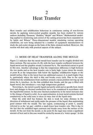
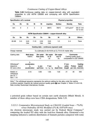
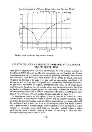
Fig. 6.20 Au: Ge diagram (after Hansen).
The casting procedure adopted in the case of the Au: Ge alloy is essentially the
same as used on the Au: Sn eutectic alloy.
As indicated in the Au : Ge diagram, Figure 6.20, the alloy system forms a simple
eutectic at 12 wt% Ge at 356°C. A melt temperature of 450° to 500°C would be used.
In both the Au: Sn and Au :Ge alloys the vapour pressures are such that there are
no significant volatiles at the melt out or at operating temperatures.
6.15.4.3 Casting 98:2 Au-Si Alloy
Au-Si forms a gold-rich eutectic at 6 wt% Si at a temperature of 370°C. The
Au-Si2% has an extremely wide freezing range 980°-370°C, see Figure 6.21. This
makes the alloy difficult to cast with tendency to hot tearing. The withdrawal settings
mentioned in Chapter 1, Section 1.7, will favour longish slow pull stroke [t1 --+ t3] with
extended [t4]. On copper plate strip cooler, adjust cooling pattern, with 'grafoil' as
required. Adequate outward top taper is required on the graphite die. The metal
temperature entering the die should be around 1100°C.
The Si addition makes the alloy somewhat aggressive to graphite, therefore it is
necessary to select one of the grade e die graphites with high thermal conductivity.
The casting rate on a 60 mm X 6 mm strip could be around 75 mm/min.
189](https://image.slidesharecdn.com/apracticalapproachtocontinuouscasting-robertwilson-230430074453-bf653c23/85/A-practical-approach-to-continuous-casting-205-320.jpg)


![Continuous casting of Copper-Based Alloys and Precious Metals
substituting part of the copper with up to 4% Cd. In this exercise comparison is
made between Ag: Cu-Ag :Cu: Cd and Ag: Cu :Sn :Mg sterling silver alloys.
The pressure up caster was used primarily because of the high toxicity of
cadmium, with a pressurised and sealed system, venting the exhaust gas via a water
trap. The atmospheric contamination, monitored over the entire casting cycle, was
held well within the international MEL (maximum exposure limit) of 0.05 mg m ?
Cd, calculated over an 8-hour period.
6.18.4.1 Casting Data
The casting operation consisted of melting and stabilising the alloys under inert
atmosphere at a furnace temperature of 1050°C and atmospheric pressure. Prior to
casting, the furnace pressure is increased to around 0.5 bar above atmospheric
pressure, thus raising the molten metal into the die, and after allowing time for the
die assembly to attain thermal stability casting commences. In this study the various
alloys were cast in the form of 9 mm X 3 mm strip with a pulse length around 4-5 mm
at a casting speed in the range 0.3-0.5 mlmin. At the end of one casting cycle, on one
alloy, pressure is lowered to atmospheric, the system is drained, charged with a
second alloy and a repeat sequence initiated.
6.18.4.2 Properties of the Cast Strip
The UTS and elongation were measured on the as-cast strip, and after reduction by
cold rolling are presented in Figure 6.23.
metal expressed in parts per thousand
700~------------~------------~------------~------------~
--+-Alloyl
~~··lg [ ~~.~~
500 ----L-----_-..,..J"---------------- ..-.. --.-------.:--.---
-------·-----··----~-~-:,-f--~-~-----·:~-;·-~··-·:---·-·-
600 -.. -
re 400
e
Z
.5
r'-J
~ 300
~1] Ag 925 Cu 75
200 -. -. -. - -. -'. -- -_.--- ---- ---- ---- -!f-I~.?~~-~-~-~?-~~-~-~~- ~-.-----:---.- ----.----- ----.-'" --.. ------.------------------ .--------------
(F1 Ag 925 Cu 52 Sn 20 Mg 3 :
100 .. ;::.: ~~~.~:. ~~::: ~g ~"'r"""""'" . .
o
20 40 60 80
AS CAST % Cold Reduction
Fig. 6.23 Sterling silver (modified specification) UTS vs. % cold reduction.
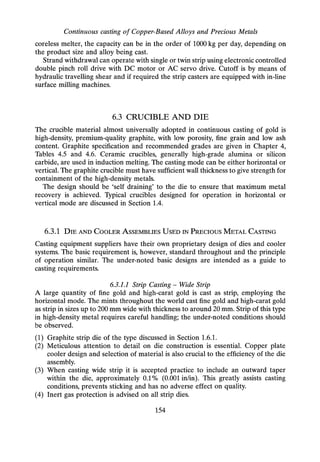
196](https://image.slidesharecdn.com/apracticalapproachtocontinuouscasting-robertwilson-230430074453-bf653c23/85/A-practical-approach-to-continuous-casting-212-320.jpg)
![Continuous Casting of Precious Metals
metal expressed in parts per thousand
~~------------~-----------------=========~======----~
[11Ag 915 Cu 75
~ ---"- -c-.-~-----------------------
~~ 'III
.-:..,
". '., [31Ag 9l5Cu 52 Sn 20 Mg 3
~ 'L•• _:: ~.-j(~---------------------------------:------------------------- L.----.,... -.....J
----------------------"(21Ali 925-eil 67 SU-5-M2 3 -----
---+- Alloy 1
..•..Alloy 2
_ .•... Alloy 3
..*.. Alloy 4
_.l(- Alloy 5
[41Ag915 ~u 32 Sn 40 Mg 3
. ,'. ,
---------- ---- ----------------- -:-x-- ---------'-,- ----- --- ------------ ~----------------------- ------------;------ ------- ----- ----------------
; ". " [51Ag92S Cu35 Cd 40 :
:. -. .
,
-...------------------------------~---------------~~.------~,--------:-- --------------------------------,-------- --------------------------
~ i' ".!
: ::'·:·'··'·':;·':·.~:~t.~.·.~::~.·.~
...
~.:~~·~..:.I,;:~:~~~;
..;~~.:.~~:;~~~;
':~7.~.7~:~:;~
'.
Q~--------~--------~-----------~----------~
AsdlsT ~
% Cold Redaction
Fig. 6.24 Sterling silver 925 (modified specification) elongation vs. % cold reduction.
Referring to the mechanical properties shown in Figures 6.23 and 6.24, the tensile
strength of the as-cast alloys is comparable, with a slightly increased average on the
modified alloys. The ductility, measured by elongation, is considerably higher in
alloys [4] and [5], i.e. the 40/0 Sn-0.35 Mg and the 40/0 Cd specifications. Deep drawing
production trials corroborate these findings.
6.18.5 Ag: Cu EUTECTIC ALLOY AND SIMILAR ALLOYS
As indicated in Figure 6.22, a eutectic is formed at 28.1 wt% Cu at a temperature of
779°C between a silver-rich solid solution containing 8.8 wt% Cu and f3 copper-rich
solid solution containing 92 wt% Cu.
This alloy has the best combination of strength, hardness and electrical properties
of any of the Ag :Cu alloys. It is used extensively for contact material in electronics.
There are a number of variants of this alloy Ag: Cu 90 :10-80: 20-75 :25 for specific
applications; these alloys have a freezing range and all cast without difficulty.
6.18.5.1 Casting Equipment
A large quantity of silver-copper alloys are cast in the horizontal mode as strip in
sizes ranging from around 50 mm width to 300 mm width. The width-to-thickness
197](https://image.slidesharecdn.com/apracticalapproachtocontinuouscasting-robertwilson-230430074453-bf653c23/85/A-practical-approach-to-continuous-casting-213-320.jpg)


![~
(J)
0-
0..
o
o
"'0
(J)
.Q
(ij
3:
.Q
"'0
C
~
~
(])
0.
0..
o
o
Z
(5
><
CO
E
~
o
Cl)
C)
e
g
e
o
~
'iii
e
c.
E
o
o
.c
c.
OO"-::J
~~(J
(J(JI
I I U.
wwO
00
""""""
00
dd
I I
LOLO
00
~O
od
00
c.
Cl)
II.
'0
o
Appendix 1
('t)('t)LOLO
0000
dddd
00"1"-
~t?19
~OLO('t)
~dd
LOOO
dd
I I
('t)LO
dd
OOLOLO
~~CICI
dddd
0000
LOOOO
OClClLO
O~~O
9999
LOOOLO
ClOOOOCl
0000
dddd
::::s
o
+-' +-' +-'
en en en
Q) Q) Q)
a: a: a:
•..
Cl)
.c
E
::::s
z
1;)1;)1;)1;)
Q) Q) Q) Q)
a: a: a: a:
~g~R~~~8m~~~R~~~~~~~~ID~~
OOOOOOClCl ClCICICI('t)('t)('t)('t)LOLO",,"LO~CI~'J
oooooo~~~~~~~ ~ ~~ ~~~o~
NNNNNNNNNNNNNNNNNNNNNNNN
"0
.c
E
~
245
~
'I
~ 0
d CI
C C L09
NN
~ClLOO
dddd
('t)
o
d](https://image.slidesharecdn.com/apracticalapproachtocontinuouscasting-robertwilson-230430074453-bf653c23/85/A-practical-approach-to-continuous-casting-261-320.jpg)


![Continuous casting of Copper-Based Alloys and Precious Metals
•..
o
Cl)
C)
c
g.
';fl.
e
o
••
"(;;
o
Q.
E
o
o
f
Cl)
.c:
o
00000000
"""~N",,"N,,,,"CJ~
00000000
OOOOOCV:>CJ
CV:>C")C")NCJOO
0000000
.c
Il.
LOLOLOI'---LO"""LO"""
00000000
Cl)
LL.
CV:>LOCV:>CV:>CV:>CV:>CV:>CV:>
00000000
c
N
1i51i51i51i51i51i)ti1i5
(]) (]) (]) (]) (]) (]) (]) (])
a: a: a: a: a: a: a: a:
:::s
o
•..
e
.c
E
:::s
z
"0
.c
E
~
248
~
.c
0>
::J
e
3:
z
o
It)
,..
><
co
E
•..
o
e
C)
c
g.
?f!.
e
o
~
"(;;
o
Q.
E
o
o
e
Cl)
.c:
s
00000
~NCJNCJ
00000
e
UJ
LOLOLOOO
~1r-r~r-r
qLOLOLOO
Mt.ri~t.ri
.c
e,
LOLOLOLOLO
00000
00000
LOLOLOLOO
cv:>cv:>cv:>cv:>~
00000
I I I I I
00000
00000
00000
CJCV:>CV:>CV:>CV:>
00000
e
LL
00000
~ ~,.....
00000
c
N
a
ggggr-f
00000
t.ri
E E E E E
(]) (]) (]) (]) (])
a:c::a:c::a:
•..
Cl)
.c
E
:::s
Z
0<.0000
oo~oo
~ ~ ~
C'JCiCiC'JC'J
(5
.c
E
l;](https://image.slidesharecdn.com/apracticalapproachtocontinuouscasting-robertwilson-230430074453-bf653c23/85/A-practical-approach-to-continuous-casting-264-320.jpg)


This document provides an overview of continuous casting of copper-based alloys and precious metals. It discusses the history and evolution of continuous casting machines and processes. It describes different types of continuous casting including vertical, vertical upward, and horizontal casting. It also discusses crucibles, furnaces, casting dies, cooling systems, and safety aspects of continuous casting operations. Finally, it reviews the continuous casting of specific metal alloys like copper, brasses, bronzes, nickel-silver, and precious metals.


