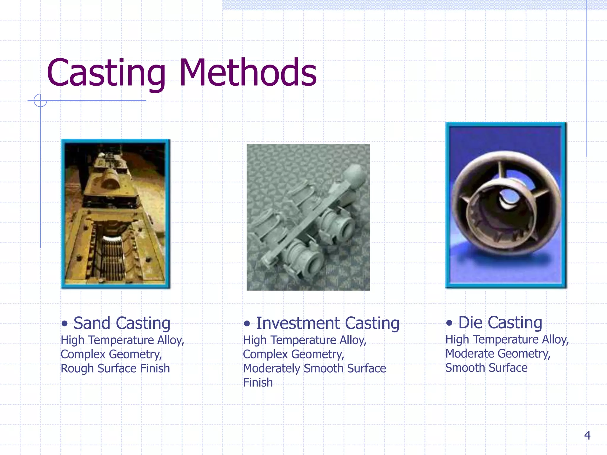
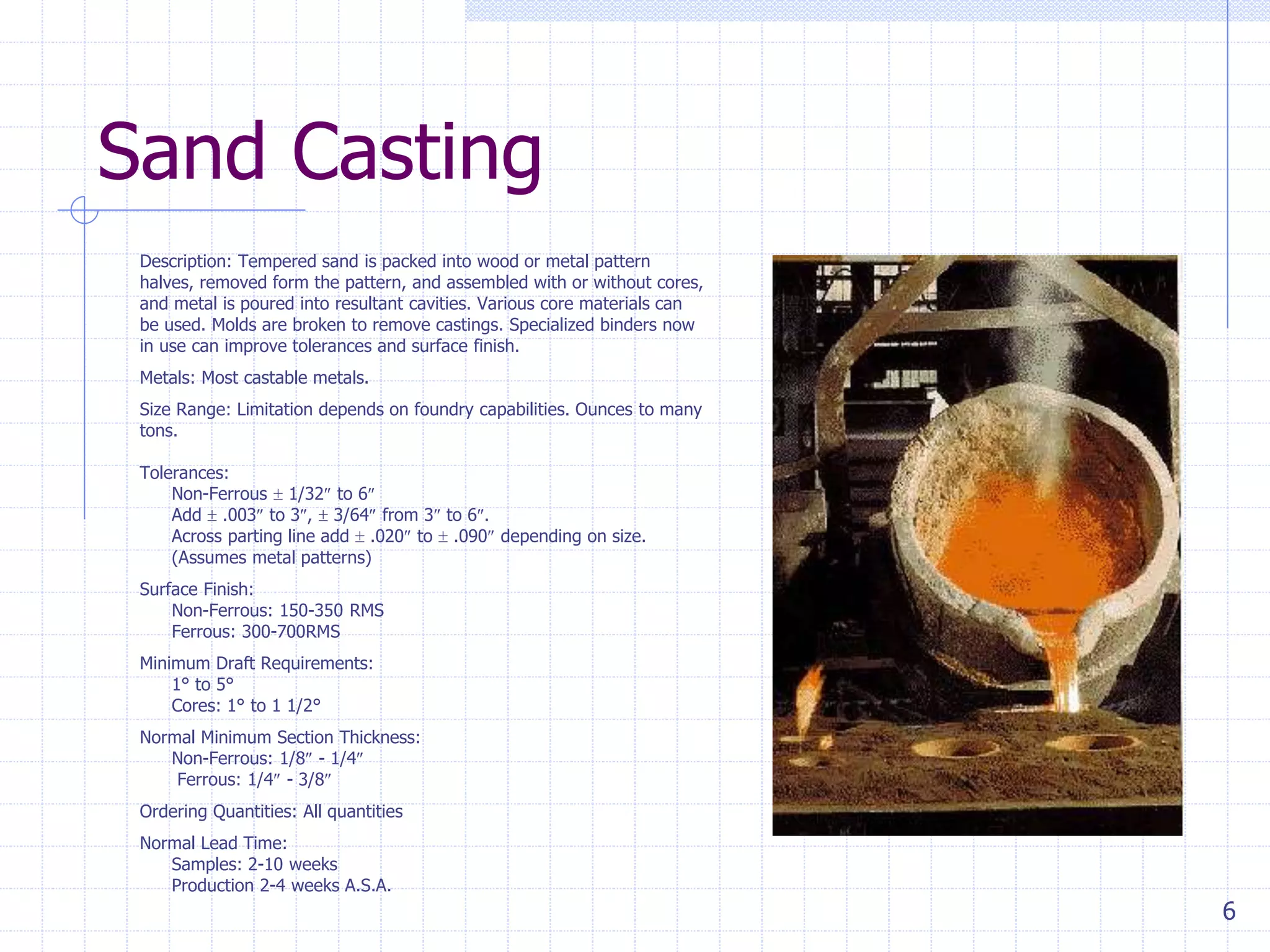
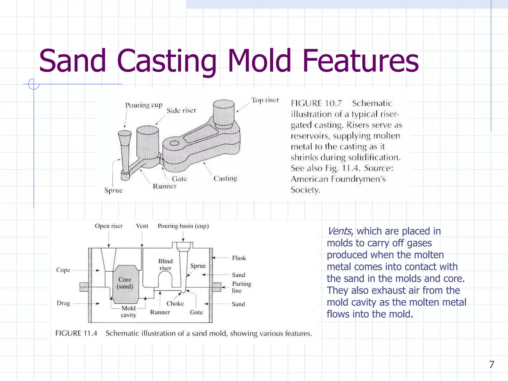
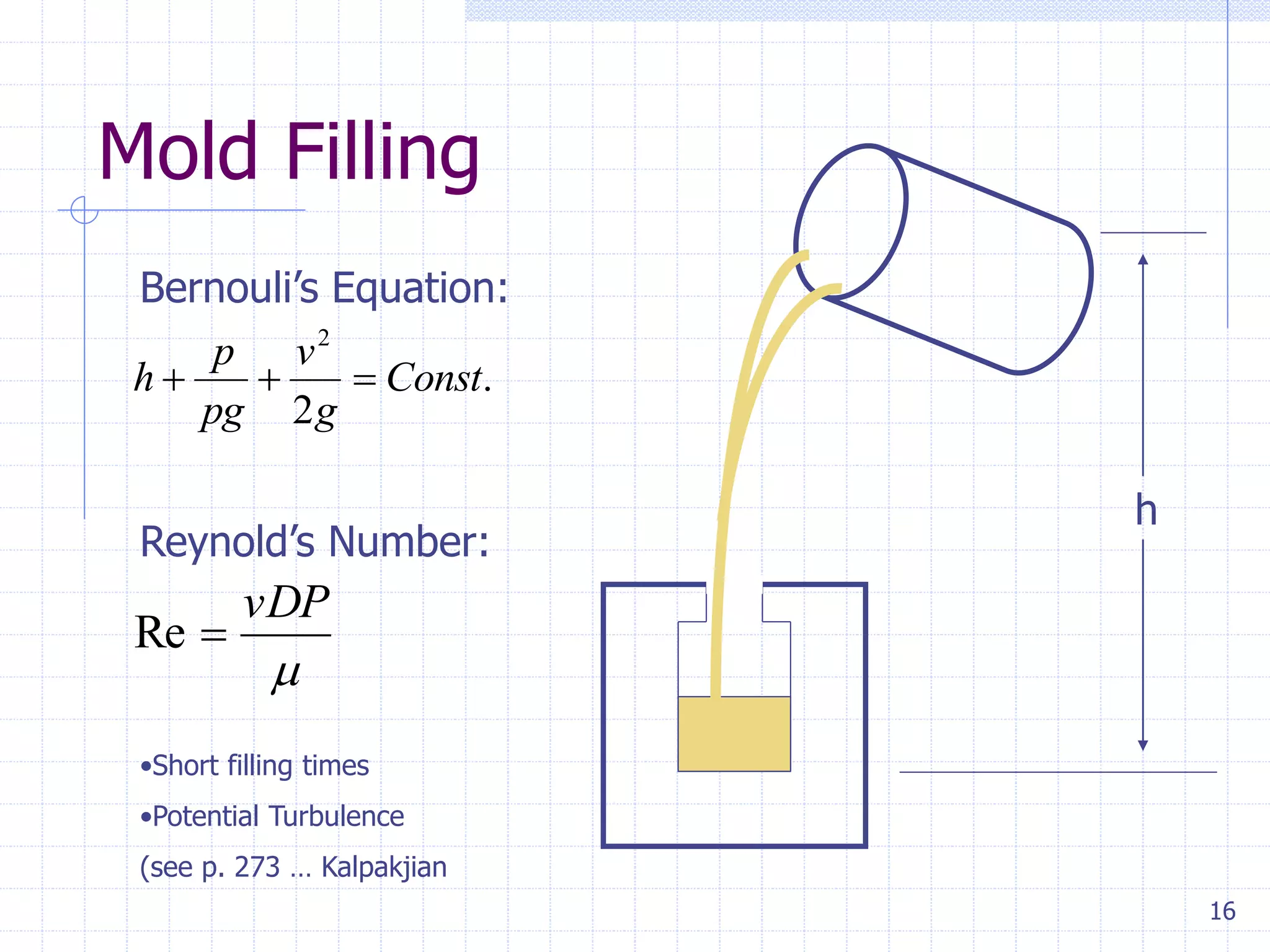
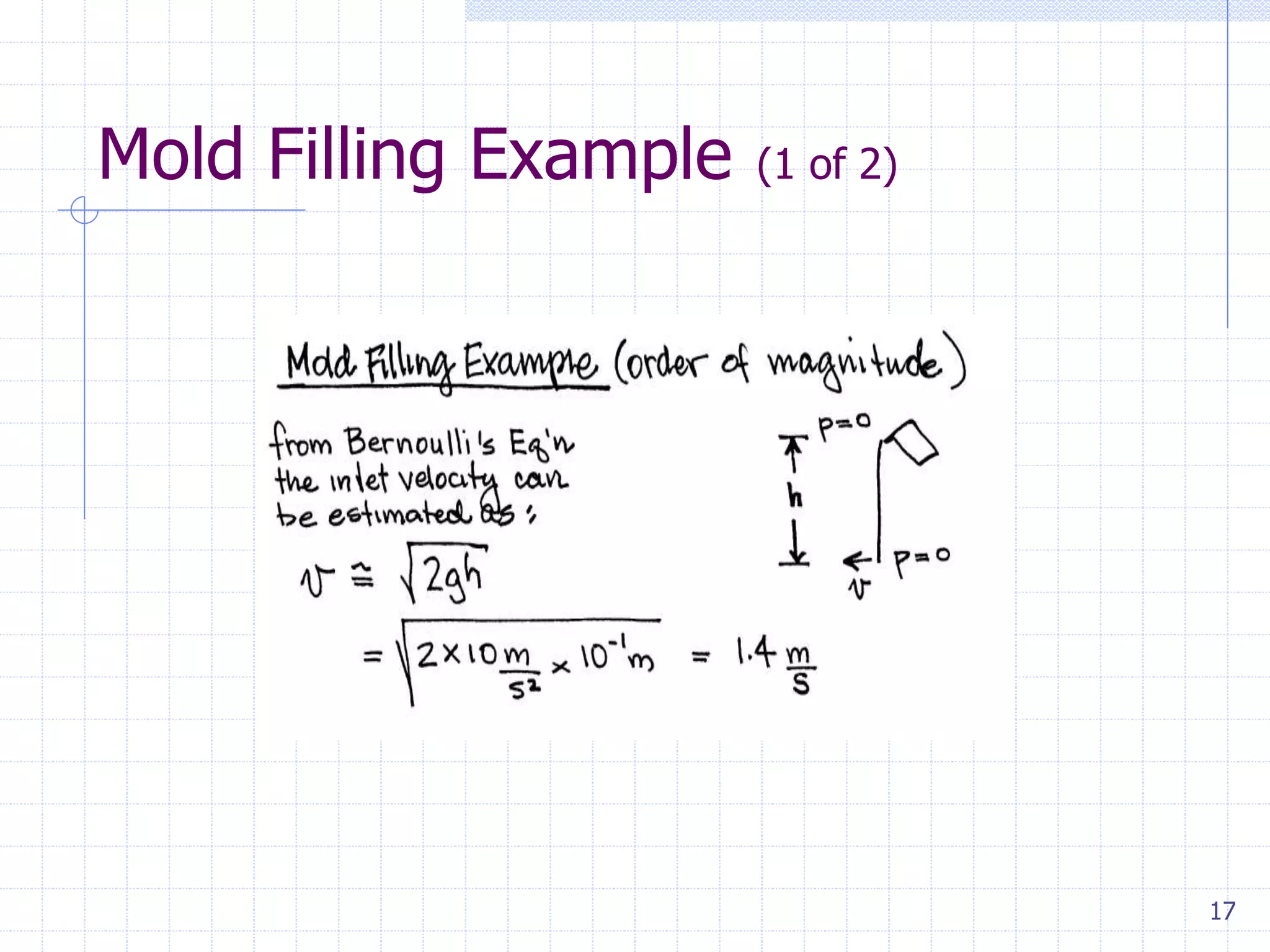
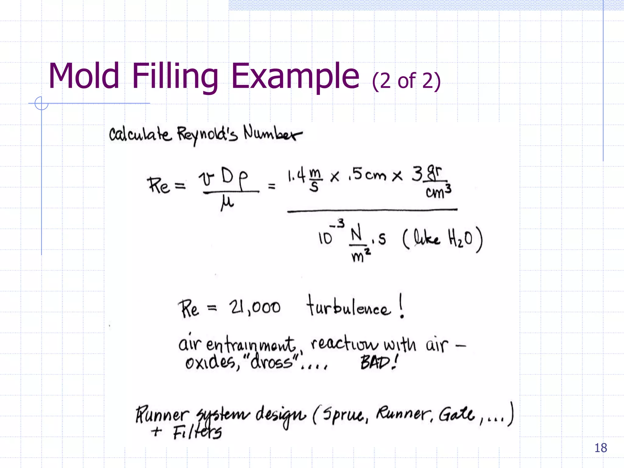
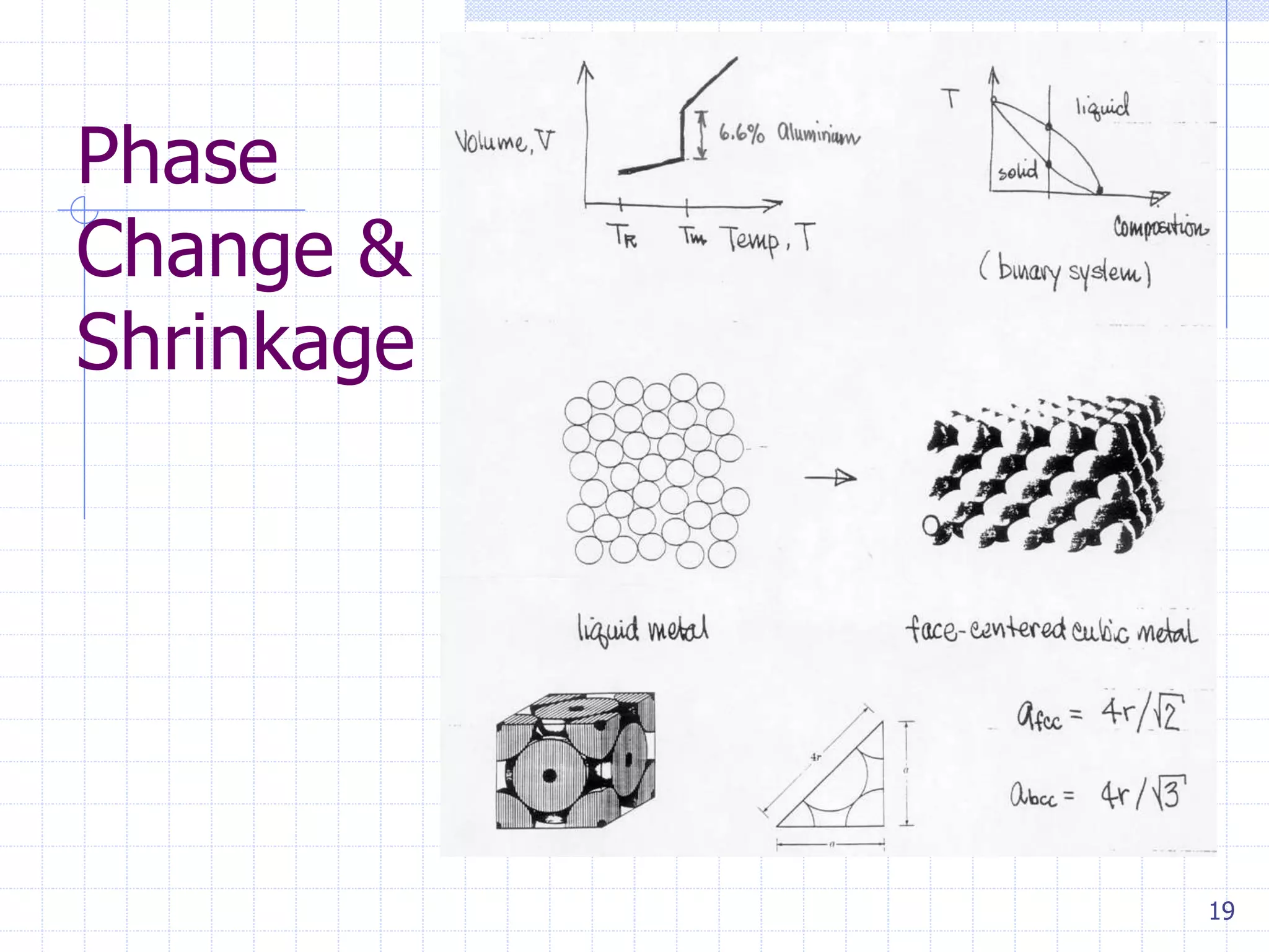
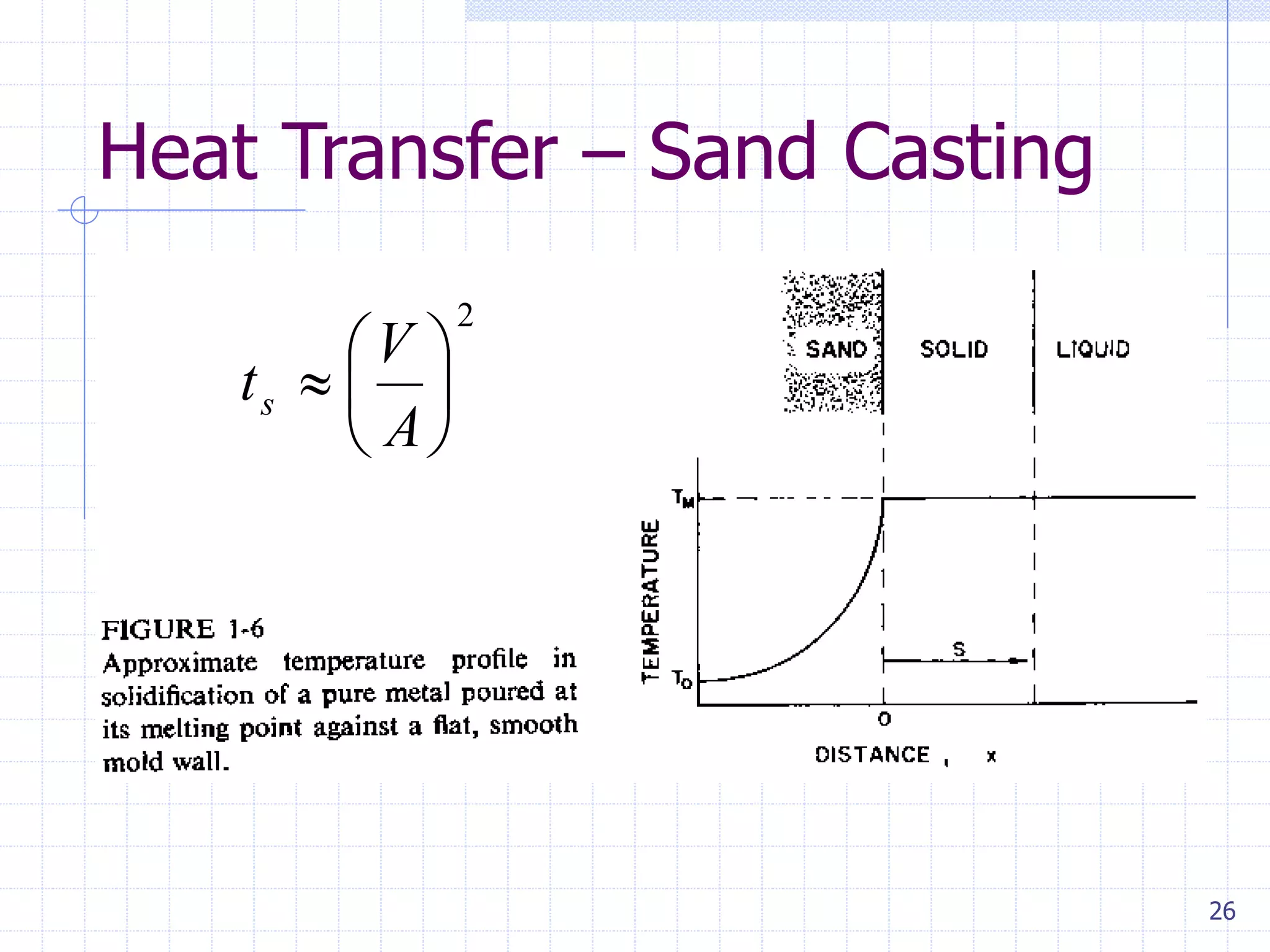
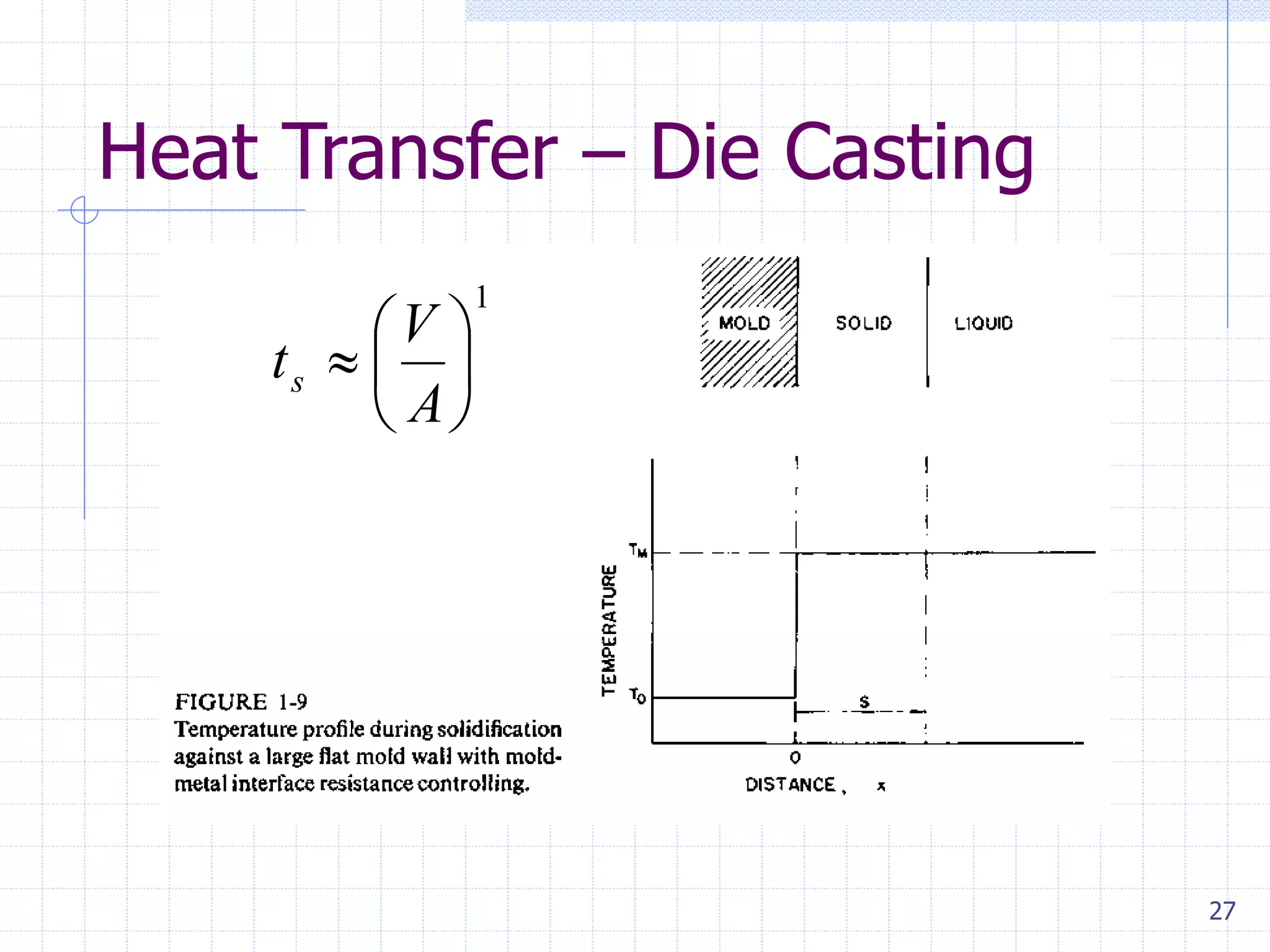
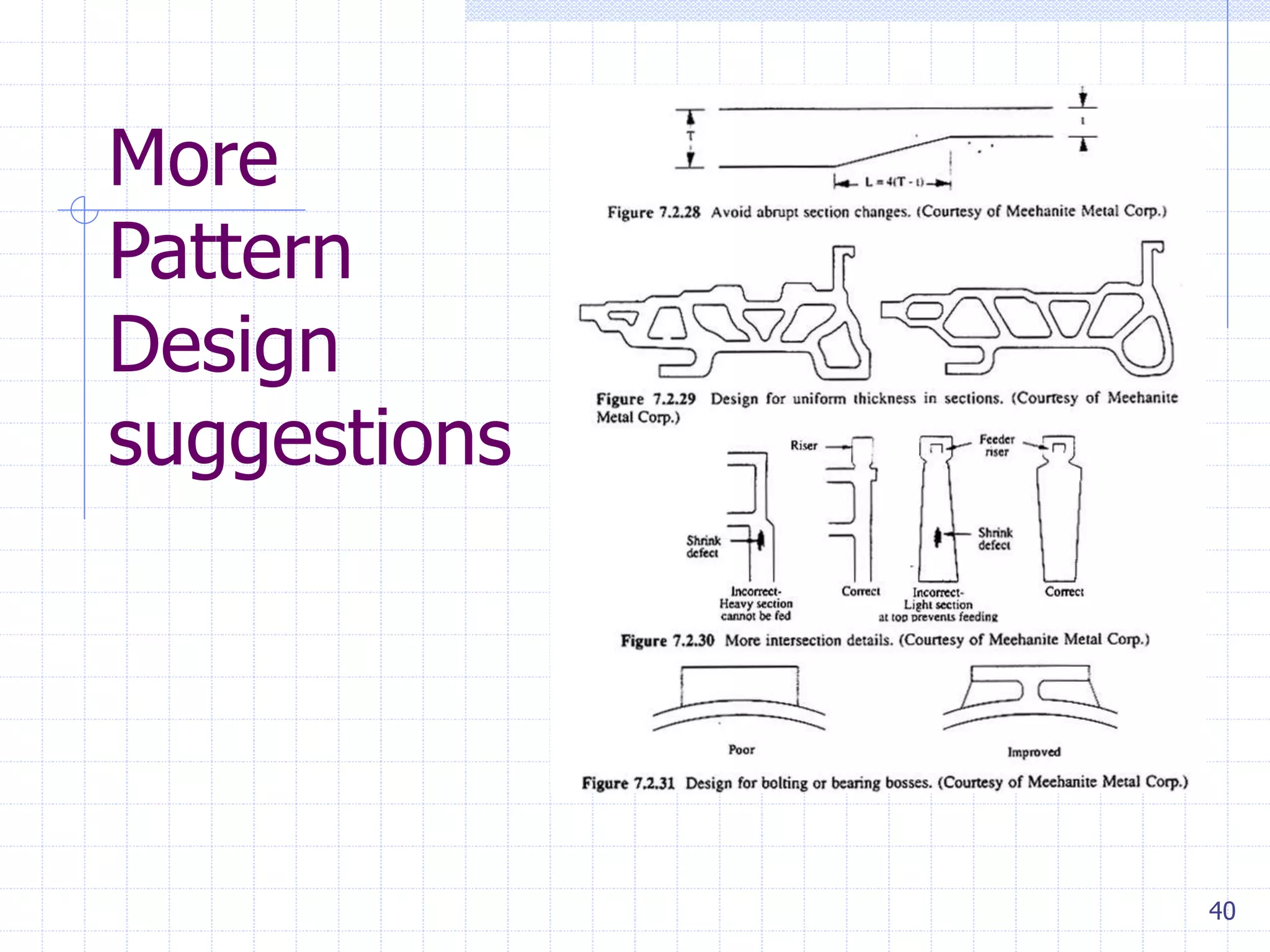
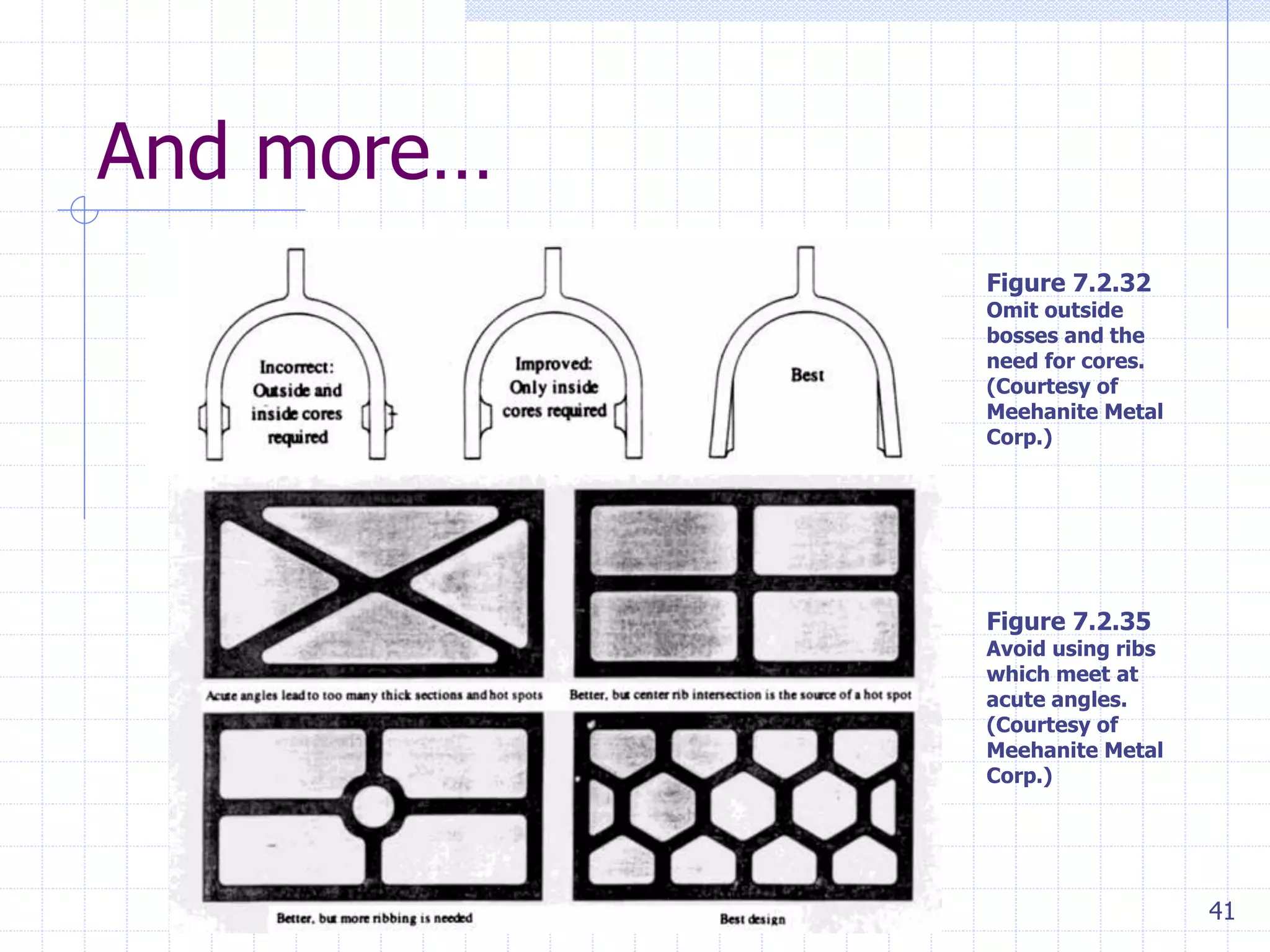
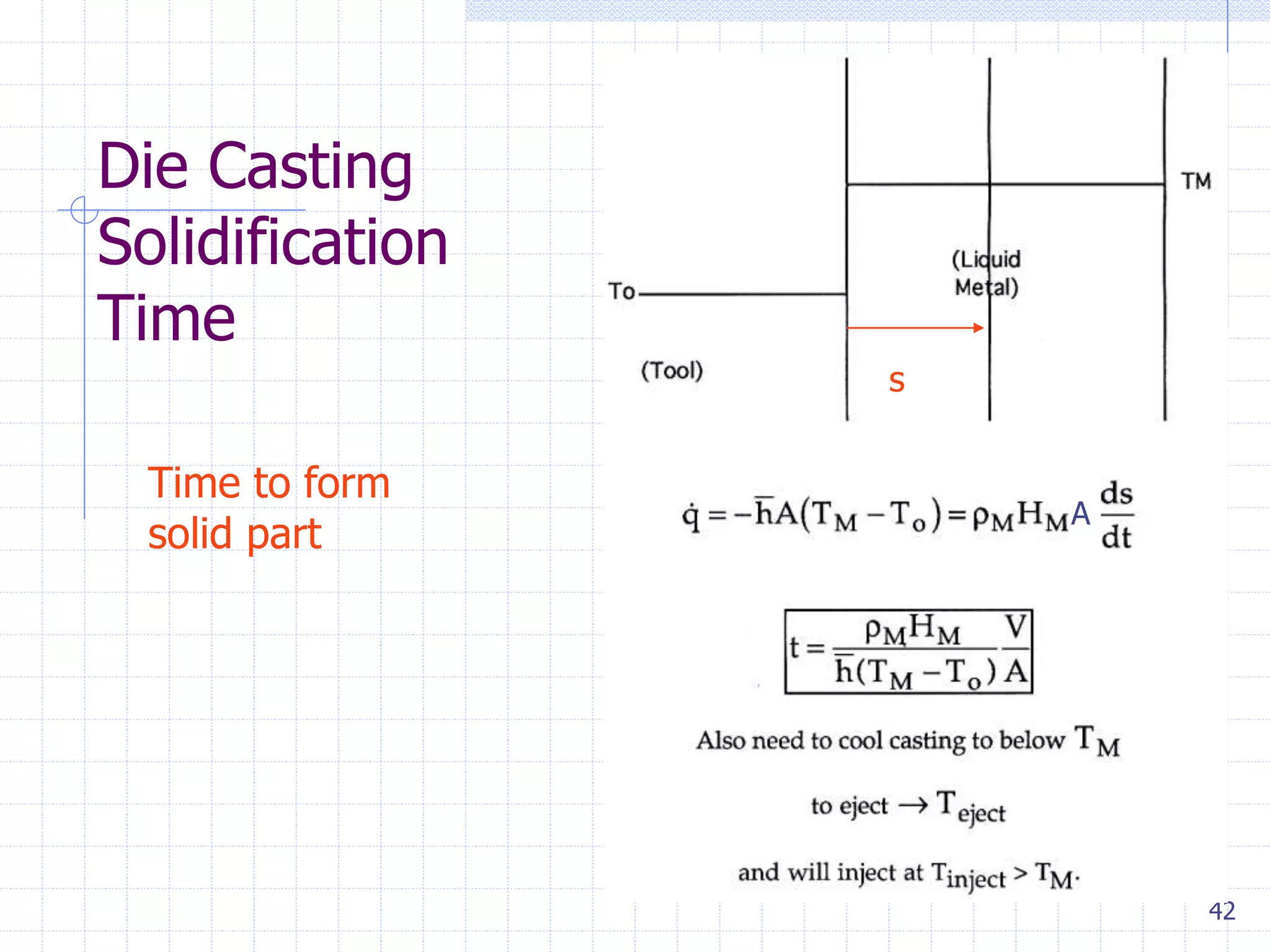
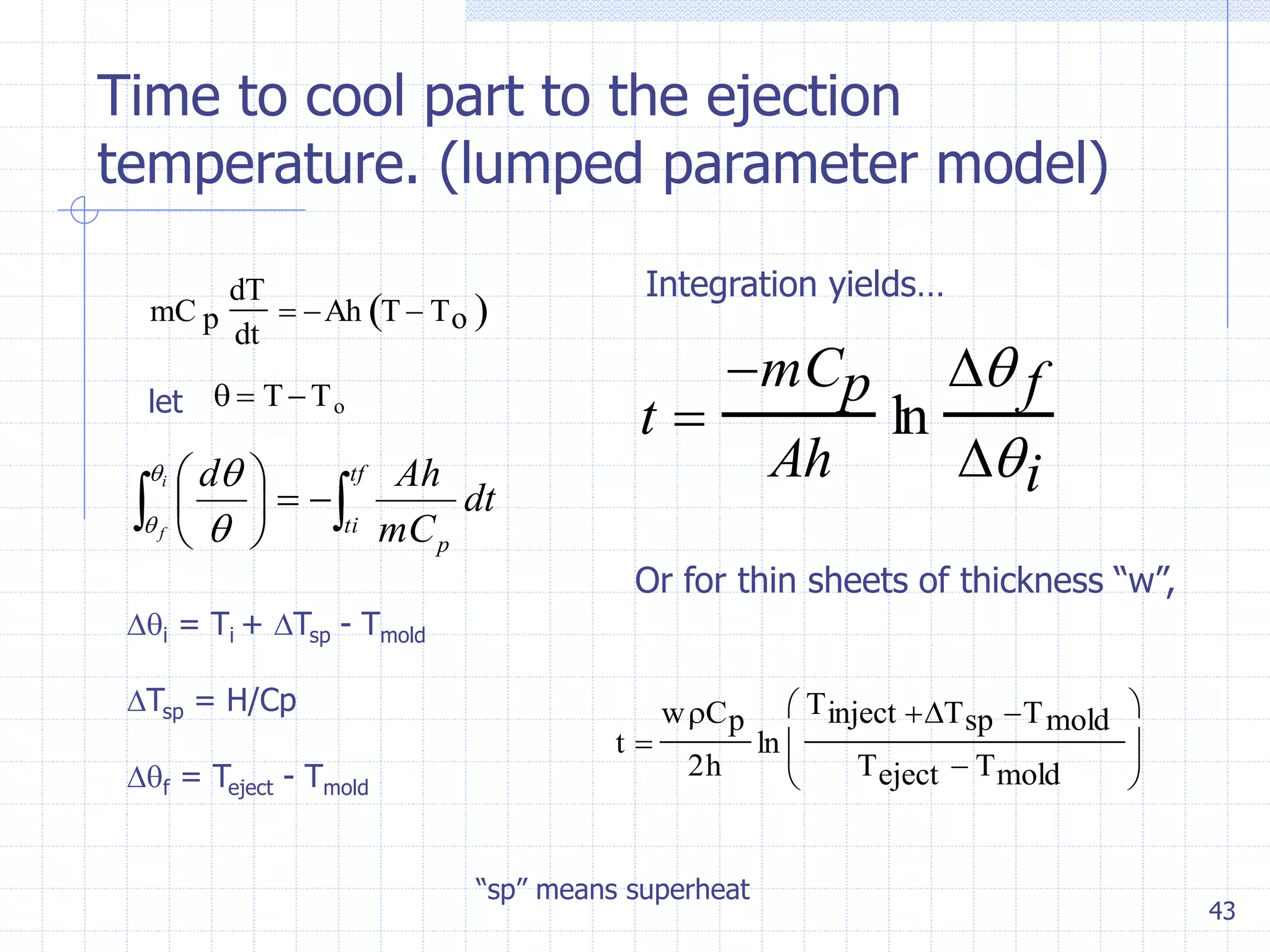
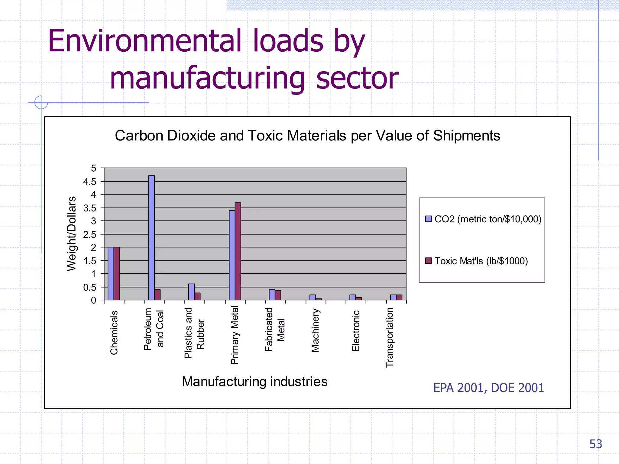
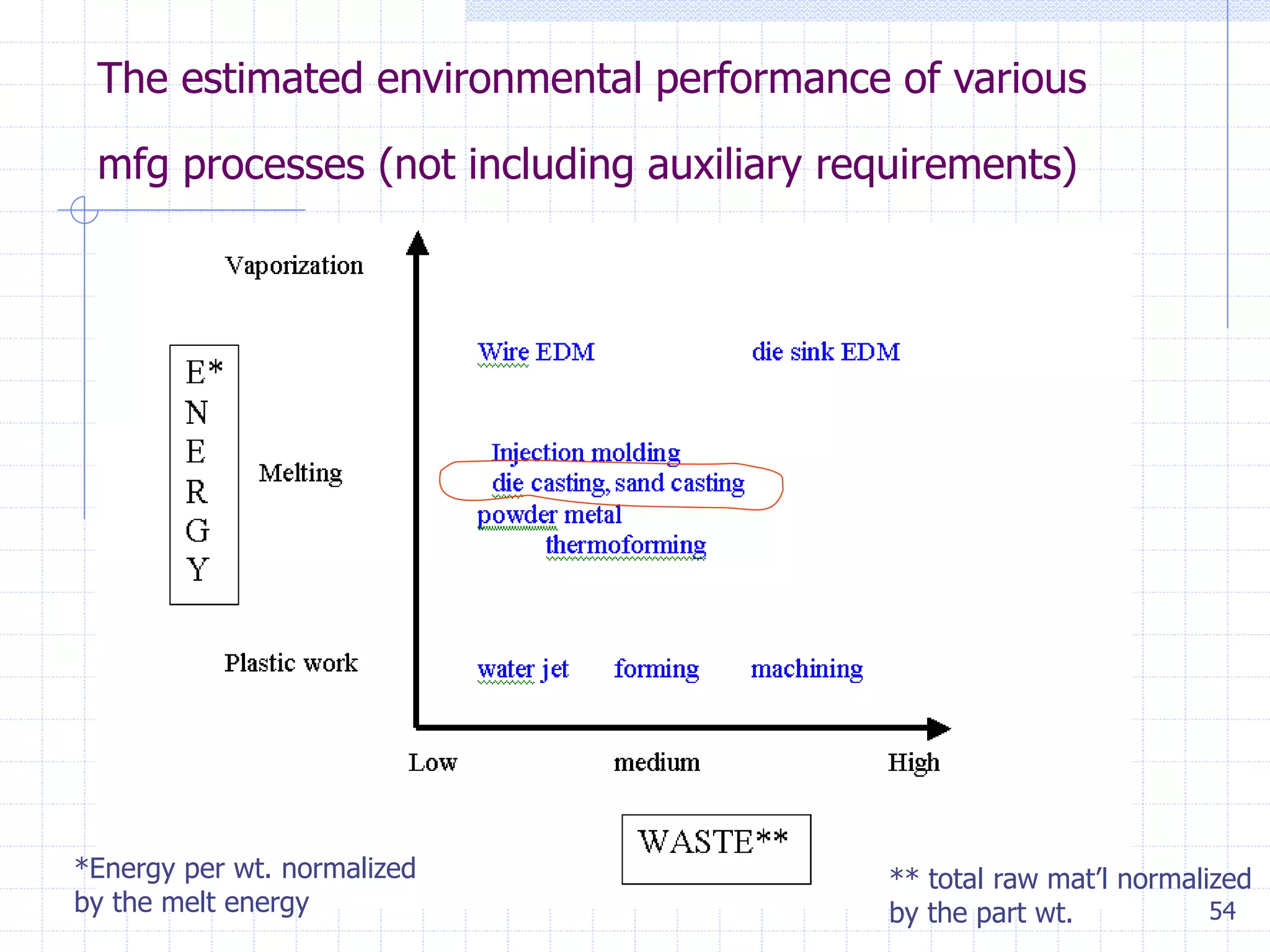
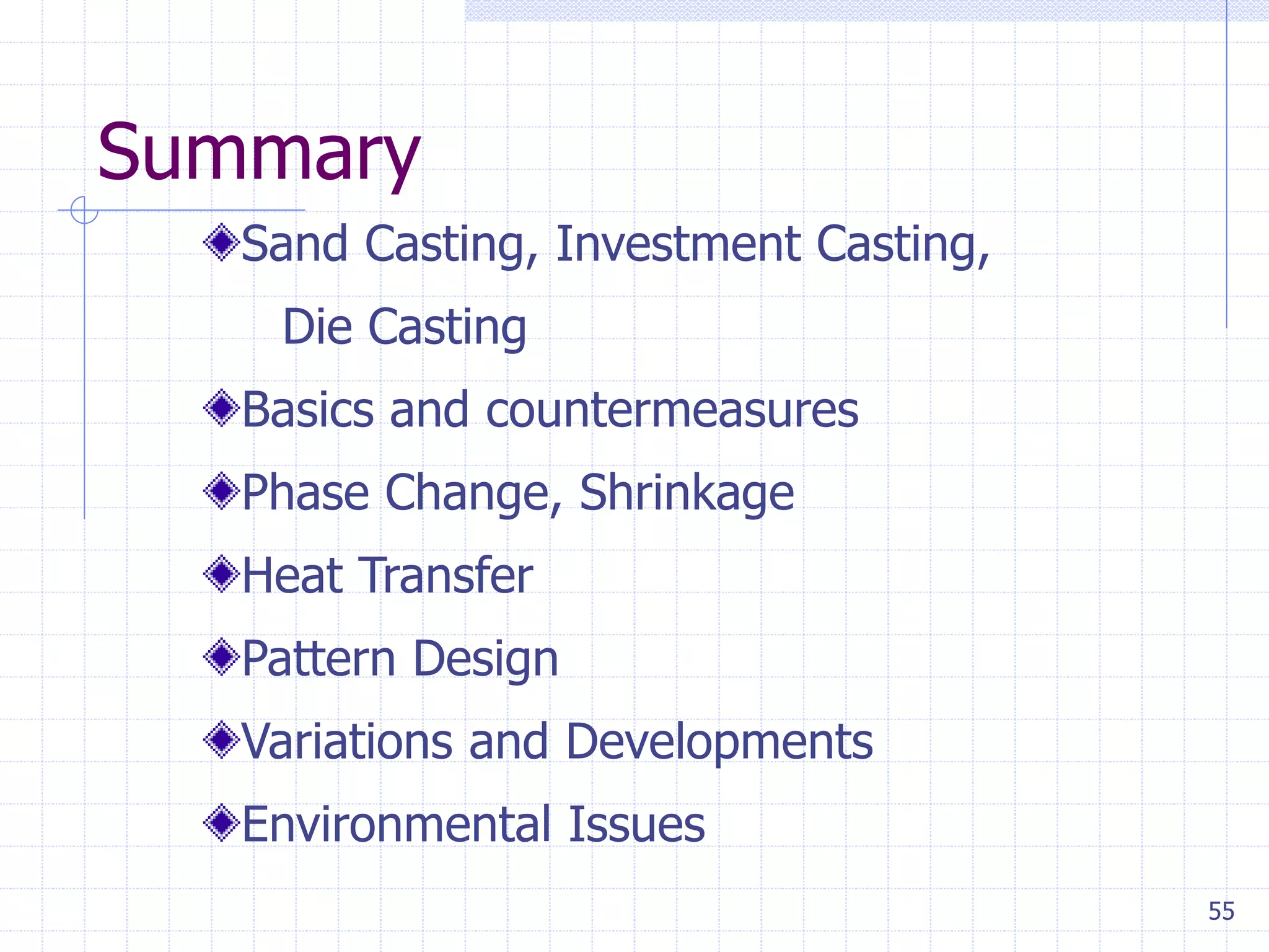
0
Casting
2.810
Prof. Timothy Gutowski
1
Casting since about 4000 BC…
Ancient Greece; bronze
statue casting circa 450BC
Iron works in early Europe,
e.g. cast iron cannons from
England circa 1543
2
Outline
Sand Casting, Investment Casting, Die Casting
Basics and countermeasures
Phase Change, Shrinkage
Heat Transfer
Pattern Design
Variations & Developments
Environmental Issues
3
Casting
Readings;
1. Kalpakjian, Chapters 10, 11,
12
2. Booothroyd, “Design for Die
Casting”
3. Flemings “Heat Flow in
Solidification”
Note: a good heat transfer reference can be found by
Prof John Lienhard online http://web.mit.edu/lienhard/www/ahtt.html
4
Casting Methods
• Sand Casting
High Temperature Alloy,
Complex Geometry,
Rough Surface Finish
• Investment Casting
High Temperature Alloy,
Complex Geometry,
Moderately Smooth Surface
Finish
• Die Casting
High Temperature Alloy,
Moderate Geometry,
Smooth Surface
5
Sand
Casting
6
Sand Casting
Description: Tempered sand is packed into wood or metal pattern
halves, removed form the pattern, and assembled with or without cores,
and metal is poured into resultant cavities. Various core materials can
be used. Molds are broken to remove castings. Specialized binders now
in use can improve tolerances and surface finish.
Metals: Most castable metals.
Size Range: Limitation depends on foundry capabilities. Ounces to many
tons.
Tolerances:
Non-Ferrous  1/32 to 6
Add  .003 to 3,  3/64 from 3 to 6.
Across parting line add  .020 to  .090 depending on size.
(Assumes metal patterns)
Surface Finish:
Non-Ferrous: 150-350 RMS
Ferrous: 300-700RMS
Minimum Draft Requirements:
1° to 5°
Cores: 1° to 1 1/2°
Normal Minimum Section Thickness:
Non-Ferrous: 1/8 - 1/4
Ferrous: 1/4 - 3/8
Ordering Quantities: All quantities
Normal Lead Time:
Samples: 2-10 weeks
Production 2-4 weeks A.S.A.
7
Sand Casting Mold Features
Vents, which are placed in
molds to carry off gases
produced when the molten
metal comes into contact with
the sand in the molds and core.
They also exhaust air from the
mold cavity as the molten metal
flows into the mold.
8
See Video from Mass Foundry
9
Production sand casting
10
Investment
Casting
The investment-casting
process, also called the
lost-wax process, was first
used during the period
4000-3500 B.C. The pattern
is made of wax or a plastic
such as polystyrene. The
sequences involved in
investment casting are
shown in Figure 11.18. The
pattern is made by injecting
molten wax or plastic into a
metal die in the shape of
the object.
11
Investment Casting
Description: Metal mold makes wax or plastic replica. There
are sprued, then surrounded with investment material, baked
out, and metal is poured in the resultant cavity. Molds are
broken to remove the castings.
Metals: Most castable metals.
Size Range: fraction of an ounce to 150 lbs..
Tolerances:
 .003 to 1/4
 .004 to 1/2,
 .005 per inch to 3
 .003 for each additional inch
Surface Finish:
63-125RMS
Minimum Draft Requirements: None
Normal Minimum Section Thickness:
.030 (Small Areas)
.060 (Large Areas)
Ordering Quantities:
Aluminum: usually under 1,000
Other metals: all quantities
Normal Lead Time:
Samples: 5-16 weeks (depending on complexity)
Production 4-12 weeks A.S.A. (depending on subsequent
operations).
Talbot Associates Inc.
12
Die Casting – Cold-Chamber Casting
Cycle in cold-chamber casting: (1) with die closed and ram withdrawn, molten metal is poured into the
chamber; (2) ram forces metal to flow into die, maintaining pressure during the cooling and solidification; and
(3) ram is withdrawn, die is opened, and part is ejected. Used for higher temperature metals eg Aluminum,
Copper and alloys
13
Die Casting – Hot-Chamber Casting
Cycle in hot-chamber casting:
(1) with die closed and
plunger withdrawn, molten
metal flows into the chamber;
(2) plunger forces metal in
chamber to flow into die,
maintaining pressure during
cooling and solidification; and
(3) plunger is withdrawn, die is
opened, and solidified part is
ejected. Finished part is shown
in (4).
14
Die Casting
Description: Molten metal is injected, under pressure, into
hardened steel dies, often water cooled. Dies are opened,
and castings are ejected.
Metals: Aluminum, Zinc, Magnesium, and limited Brass.
Size Range: Not normally over 2 feet square. Some foundries
capable of larger sizes.
Tolerances:
Al and Mg  .002/in.
Zinc  .0015/in.
Brass  .001/in.
Add  .001 to  .015 across parting line depending on
size
Surface Finish: 32-63RMS
Minimum Draft Requirements:
Al & Mg: 1° to 3°
Zinc: 1/2° to 2°
Brass: 2° to 5°
Normal Minimum Section Thickness:
Al & Mg: .03 Small Parts: .06 Medium Parts
Zinc: .03 Small Parts: .045 Medium Parts
Brass: .025 Small Parts: .040 Medium Parts
Ordering Quantities:
Usually 2,500 and up.
Normal Lead Time:
Samples: 12-20 weeks
Production: ASAP after approval.
15
High Melt Temperature
•Chemical Activity
•High Latent Heat
•Handling
•Off-gassing
3000° C
0° C
1000° C
2000° C
Tungsten Carbide, WC,
Silicon Carbide, SiC
Molybdenum
Alumina Al2O3
Platinum, Pt
Titanium, Ti
IronFE, Plain Carbon Steels, low alloy, stainless
Nickel, Ni
Nickel Allows
Cubic Zirconia, ZrO2
Silicon, Si
Copper, Cu, Bronze, Brass
Aluminum
Magnesium
Zinc, Zn
PTFE (Teflon)
Tin, Sn
HDPE
Nylon
Acetal
16
Mold Filling
Bernouli’s Equation:
Reynold’s Number:
•Short filling times
•Potential Turbulence
(see p. 273 … Kalpakjian
.
2
2
Const
g
v
pg
p
h 

vDP
Re
h
17
Mold Filling Example (1 of 2)
18
Mold Filling Example (2 of 2)
19
Phase
Change &
Shrinkage
20
Solidification of a binary alloy
21
Composition change during
solidification
22
Solidification
23
Cast structures
Schematic illustration of three cast
structures solidified in a square mold:
(a) pure metals; (b) solid solution
alloys; and © structure obtained by
using nucleating agents. Source: G. W.
Form, J. F. Wallace, and A. Cibula
24
Pop quiz; If you top fill the
mold below, what will the part
look like after solidification?
25
Can you explain these
features?
26
Heat Transfer – Sand Casting
2







A
V
ts
27
Heat Transfer – Die Casting
1







A
V
ts
28
Steady State Conduction Heat Transfer
Figure 1
29
Steady State Conduction Heat Transfer
Figure 2
30
Thermal Conductivity “k” of Various
Materials for Parts and Molds (W/m °K)
Copper 394
Aluminum 222
Iron 29
Sand 0.61
PMMA 0.20
PVC 0.16
dx
dT
kq 
31
Film Coefficients W/m2°K
Typical die casting 5,000
Natural convection 1 - 10
Flowing air 10 - 50
 Thq 
32
Transient Heat Transfer
33
Sand Casting (see Flemings)
34
Sand Casting (see Flemings)
35
Solidification Time
enthapy
Use Flemings
result here
36
Solidification Time (cont.)
37
Cooling Time; thin slab
38
Cooling time;intersection


























1
1
2
1
1
2
h
L
h
A
V
39
Pattern Design suggestions
40
More
Pattern
Design
suggestions
41
And more…
Figure 7.2.32
Omit outside
bosses and the
need for cores.
(Courtesy of
Meehanite Metal
Corp.)
Figure 7.2.35
Avoid using ribs
which meet at
acute angles.
(Courtesy of
Meehanite Metal
Corp.)
42
Die Casting
Solidification
Time
s
Time to form
solid part
A
43
Time to cool part to the ejection
temperature. (lumped parameter model)
mC p
dT
dt
 Ah T  To 
let   TTo
 




 tf
ti
p
dt
mC
Ahdi
f

 

i = Ti + Tsp - Tmold
Tsp = H/Cp
f = Teject - Tmold
t 
mCp
Ah
ln
 f
i
Integration yields…
t 
wCp
2h
ln
Tinject Tsp Tmold
Teject  Tmold






Or for thin sheets of thickness “w”,
“sp” means superheat
44
Pattern Design Issues (Alum)
Shrinkage Allowance .013/1
Machining Allowance 1/16”
Minimum thickness 3/16”
Parting Line
Draft Angle 3 to 5%
Uniform Thickness
45
Pattern Design
Table 12.1
Normal Shrinkage Allowance for
Some Metals Cast in Sand Molds
Metal Percent
Gray cast iron 0.83 – 1.3
White cast iron 2.1
Malleable cast iron0.78 – 1.0
Aluminum alloys 1.3
Magnesium alloys 1.3
Yellow brass 1.3 – 1.6
Phosphor bronze 1.0 – 1.6
Aluminum bronze 2.1
High-manganese steel 2.6
46
Variations and Developments
Continuous casting
Lost foam molding
3D Printing of Investment tooling
Direct printing with metal droplets
Uniform metal spray
47
Continuous casting ref AISI
Steel from the electric or basic oxygen furnace is tapped into a ladle and taken to
the continuous casting machine. The ladle is raised onto a turret that rotates the ladle
into the casting position above the tundish. Referring to Figure 2, liquid steel flows out
of the ladle (1) into the tundish (2), and then into a water-cooled copper mold (3).
Solidification begins in the mold, and continues through the First Zone (4) and Strand Guide (5).
In this configuration, the strand is straightened (6), torch-cut (8), then discharged (12)
for intermediate storage or hot charged for finished rolling.
48
3D Printing
of Investment cast tooling
49
Shell and part (Turbine blade)
50
Microcasting of droplets
CMU
MIT
51
Environmental Issues
Smelting
Energy
Off-gassing see AFS webpage on green sand emissions;
http://www.afsinc.org/environmental.html
Cooling water
Waste sand disposal
Off shore locations
52
Metal Smelting; reducing oxides and
sulfides to metal…..
http://www.steel.org/learning/howmade/blast_furnace.htm
53
Environmental loads by
manufacturing sector
Carbon Dioxide and Toxic Materials per Value of Shipments
0
0.5
1
1.5
2
2.5
3
3.5
4
4.5
5
Chemicals
Petroleum
andCoal
Plasticsand
Rubber
PrimaryMetal
Fabricated
Metal
Machinery
Electronic
Transportation
Manufacturing industries
Weight/Dollars
CO2 (metric ton/$10,000)
Toxic Mat'ls (lb/$1000)
EPA 2001, DOE 2001
54
The estimated environmental performance of various
mfg processes (not including auxiliary requirements)
*Energy per wt. normalized
by the melt energy
** total raw mat’l normalized
by the part wt.
55
Summary
Sand Casting, Investment Casting,
Die Casting
Basics and countermeasures
Phase Change, Shrinkage
Heat Transfer
Pattern Design
Variations and Developments
Environmental Issues

Casting Process

  • 1.
  • 2.
    1 Casting since about4000 BC… Ancient Greece; bronze statue casting circa 450BC Iron works in early Europe, e.g. cast iron cannons from England circa 1543
  • 3.
    2 Outline Sand Casting, InvestmentCasting, Die Casting Basics and countermeasures Phase Change, Shrinkage Heat Transfer Pattern Design Variations & Developments Environmental Issues
  • 4.
    3 Casting Readings; 1. Kalpakjian, Chapters10, 11, 12 2. Booothroyd, “Design for Die Casting” 3. Flemings “Heat Flow in Solidification” Note: a good heat transfer reference can be found by Prof John Lienhard online http://web.mit.edu/lienhard/www/ahtt.html
  • 5.
    4 Casting Methods • SandCasting High Temperature Alloy, Complex Geometry, Rough Surface Finish • Investment Casting High Temperature Alloy, Complex Geometry, Moderately Smooth Surface Finish • Die Casting High Temperature Alloy, Moderate Geometry, Smooth Surface
  • 6.
  • 7.
    6 Sand Casting Description: Temperedsand is packed into wood or metal pattern halves, removed form the pattern, and assembled with or without cores, and metal is poured into resultant cavities. Various core materials can be used. Molds are broken to remove castings. Specialized binders now in use can improve tolerances and surface finish. Metals: Most castable metals. Size Range: Limitation depends on foundry capabilities. Ounces to many tons. Tolerances: Non-Ferrous  1/32 to 6 Add  .003 to 3,  3/64 from 3 to 6. Across parting line add  .020 to  .090 depending on size. (Assumes metal patterns) Surface Finish: Non-Ferrous: 150-350 RMS Ferrous: 300-700RMS Minimum Draft Requirements: 1° to 5° Cores: 1° to 1 1/2° Normal Minimum Section Thickness: Non-Ferrous: 1/8 - 1/4 Ferrous: 1/4 - 3/8 Ordering Quantities: All quantities Normal Lead Time: Samples: 2-10 weeks Production 2-4 weeks A.S.A.
  • 8.
    7 Sand Casting MoldFeatures Vents, which are placed in molds to carry off gases produced when the molten metal comes into contact with the sand in the molds and core. They also exhaust air from the mold cavity as the molten metal flows into the mold.
  • 9.
    8 See Video fromMass Foundry
  • 10.
  • 11.
    10 Investment Casting The investment-casting process, alsocalled the lost-wax process, was first used during the period 4000-3500 B.C. The pattern is made of wax or a plastic such as polystyrene. The sequences involved in investment casting are shown in Figure 11.18. The pattern is made by injecting molten wax or plastic into a metal die in the shape of the object.
  • 12.
    11 Investment Casting Description: Metalmold makes wax or plastic replica. There are sprued, then surrounded with investment material, baked out, and metal is poured in the resultant cavity. Molds are broken to remove the castings. Metals: Most castable metals. Size Range: fraction of an ounce to 150 lbs.. Tolerances:  .003 to 1/4  .004 to 1/2,  .005 per inch to 3  .003 for each additional inch Surface Finish: 63-125RMS Minimum Draft Requirements: None Normal Minimum Section Thickness: .030 (Small Areas) .060 (Large Areas) Ordering Quantities: Aluminum: usually under 1,000 Other metals: all quantities Normal Lead Time: Samples: 5-16 weeks (depending on complexity) Production 4-12 weeks A.S.A. (depending on subsequent operations). Talbot Associates Inc.
  • 13.
    12 Die Casting –Cold-Chamber Casting Cycle in cold-chamber casting: (1) with die closed and ram withdrawn, molten metal is poured into the chamber; (2) ram forces metal to flow into die, maintaining pressure during the cooling and solidification; and (3) ram is withdrawn, die is opened, and part is ejected. Used for higher temperature metals eg Aluminum, Copper and alloys
  • 14.
    13 Die Casting –Hot-Chamber Casting Cycle in hot-chamber casting: (1) with die closed and plunger withdrawn, molten metal flows into the chamber; (2) plunger forces metal in chamber to flow into die, maintaining pressure during cooling and solidification; and (3) plunger is withdrawn, die is opened, and solidified part is ejected. Finished part is shown in (4).
  • 15.
    14 Die Casting Description: Moltenmetal is injected, under pressure, into hardened steel dies, often water cooled. Dies are opened, and castings are ejected. Metals: Aluminum, Zinc, Magnesium, and limited Brass. Size Range: Not normally over 2 feet square. Some foundries capable of larger sizes. Tolerances: Al and Mg  .002/in. Zinc  .0015/in. Brass  .001/in. Add  .001 to  .015 across parting line depending on size Surface Finish: 32-63RMS Minimum Draft Requirements: Al & Mg: 1° to 3° Zinc: 1/2° to 2° Brass: 2° to 5° Normal Minimum Section Thickness: Al & Mg: .03 Small Parts: .06 Medium Parts Zinc: .03 Small Parts: .045 Medium Parts Brass: .025 Small Parts: .040 Medium Parts Ordering Quantities: Usually 2,500 and up. Normal Lead Time: Samples: 12-20 weeks Production: ASAP after approval.
  • 16.
    15 High Melt Temperature •ChemicalActivity •High Latent Heat •Handling •Off-gassing 3000° C 0° C 1000° C 2000° C Tungsten Carbide, WC, Silicon Carbide, SiC Molybdenum Alumina Al2O3 Platinum, Pt Titanium, Ti IronFE, Plain Carbon Steels, low alloy, stainless Nickel, Ni Nickel Allows Cubic Zirconia, ZrO2 Silicon, Si Copper, Cu, Bronze, Brass Aluminum Magnesium Zinc, Zn PTFE (Teflon) Tin, Sn HDPE Nylon Acetal
  • 17.
    16 Mold Filling Bernouli’s Equation: Reynold’sNumber: •Short filling times •Potential Turbulence (see p. 273 … Kalpakjian . 2 2 Const g v pg p h   vDP Re h
  • 18.
  • 19.
  • 20.
  • 21.
  • 22.
  • 23.
  • 24.
    23 Cast structures Schematic illustrationof three cast structures solidified in a square mold: (a) pure metals; (b) solid solution alloys; and © structure obtained by using nucleating agents. Source: G. W. Form, J. F. Wallace, and A. Cibula
  • 25.
    24 Pop quiz; Ifyou top fill the mold below, what will the part look like after solidification?
  • 26.
    25 Can you explainthese features?
  • 27.
    26 Heat Transfer –Sand Casting 2        A V ts
  • 28.
    27 Heat Transfer –Die Casting 1        A V ts
  • 29.
    28 Steady State ConductionHeat Transfer Figure 1
  • 30.
    29 Steady State ConductionHeat Transfer Figure 2
  • 31.
    30 Thermal Conductivity “k”of Various Materials for Parts and Molds (W/m °K) Copper 394 Aluminum 222 Iron 29 Sand 0.61 PMMA 0.20 PVC 0.16 dx dT kq 
  • 32.
    31 Film Coefficients W/m2°K Typicaldie casting 5,000 Natural convection 1 - 10 Flowing air 10 - 50  Thq 
  • 33.
  • 34.
  • 35.
  • 36.
  • 37.
  • 38.
  • 39.
  • 40.
  • 41.
  • 42.
    41 And more… Figure 7.2.32 Omitoutside bosses and the need for cores. (Courtesy of Meehanite Metal Corp.) Figure 7.2.35 Avoid using ribs which meet at acute angles. (Courtesy of Meehanite Metal Corp.)
  • 43.
  • 44.
    43 Time to coolpart to the ejection temperature. (lumped parameter model) mC p dT dt  Ah T  To  let   TTo        tf ti p dt mC Ahdi f     i = Ti + Tsp - Tmold Tsp = H/Cp f = Teject - Tmold t  mCp Ah ln  f i Integration yields… t  wCp 2h ln Tinject Tsp Tmold Teject  Tmold       Or for thin sheets of thickness “w”, “sp” means superheat
  • 45.
    44 Pattern Design Issues(Alum) Shrinkage Allowance .013/1 Machining Allowance 1/16” Minimum thickness 3/16” Parting Line Draft Angle 3 to 5% Uniform Thickness
  • 46.
    45 Pattern Design Table 12.1 NormalShrinkage Allowance for Some Metals Cast in Sand Molds Metal Percent Gray cast iron 0.83 – 1.3 White cast iron 2.1 Malleable cast iron0.78 – 1.0 Aluminum alloys 1.3 Magnesium alloys 1.3 Yellow brass 1.3 – 1.6 Phosphor bronze 1.0 – 1.6 Aluminum bronze 2.1 High-manganese steel 2.6
  • 47.
    46 Variations and Developments Continuouscasting Lost foam molding 3D Printing of Investment tooling Direct printing with metal droplets Uniform metal spray
  • 48.
    47 Continuous casting refAISI Steel from the electric or basic oxygen furnace is tapped into a ladle and taken to the continuous casting machine. The ladle is raised onto a turret that rotates the ladle into the casting position above the tundish. Referring to Figure 2, liquid steel flows out of the ladle (1) into the tundish (2), and then into a water-cooled copper mold (3). Solidification begins in the mold, and continues through the First Zone (4) and Strand Guide (5). In this configuration, the strand is straightened (6), torch-cut (8), then discharged (12) for intermediate storage or hot charged for finished rolling.
  • 49.
  • 50.
    49 Shell and part(Turbine blade)
  • 51.
  • 52.
    51 Environmental Issues Smelting Energy Off-gassing seeAFS webpage on green sand emissions; http://www.afsinc.org/environmental.html Cooling water Waste sand disposal Off shore locations
  • 53.
    52 Metal Smelting; reducingoxides and sulfides to metal….. http://www.steel.org/learning/howmade/blast_furnace.htm
  • 54.
    53 Environmental loads by manufacturingsector Carbon Dioxide and Toxic Materials per Value of Shipments 0 0.5 1 1.5 2 2.5 3 3.5 4 4.5 5 Chemicals Petroleum andCoal Plasticsand Rubber PrimaryMetal Fabricated Metal Machinery Electronic Transportation Manufacturing industries Weight/Dollars CO2 (metric ton/$10,000) Toxic Mat'ls (lb/$1000) EPA 2001, DOE 2001
  • 55.
    54 The estimated environmentalperformance of various mfg processes (not including auxiliary requirements) *Energy per wt. normalized by the melt energy ** total raw mat’l normalized by the part wt.
  • 56.
    55 Summary Sand Casting, InvestmentCasting, Die Casting Basics and countermeasures Phase Change, Shrinkage Heat Transfer Pattern Design Variations and Developments Environmental Issues