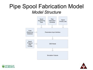
RAMZI LABBAN

DR. SIMAAN M. ABOURIZK

MANAGER, COMPUTER MODELING
& SIMULATION
CCC
PHD CANDIDATE
UNIVERSITY OF ALBERTA

PROFESSOR
UNIVERSITY OF ALBERTA

MR. ZUHAIR HADDAD

DR. AMR EL-SERSY

VICE PRESIDENT, CORPORATE
AFFAIRS & CIO
CCC

GROUP MANAGER, LEARNING &
INNOVATION
CCC
Agenda
• Introduction
• Pipe Spool Fabrication Model
–
–
–
–
–

•
•
•
•
•

Background
Simulator Design and Development
Product Definitions
Process Definitions (Activity Flow, Resources)
Model Structure (Parameters Interface, DES Model, Outputs)

Potential Benefits
Future Work
Conclusions
Acknowledgements
Q&A
Introduction
• Pipe spool fabrication
– A major component of construction operations on
large industrial projects
– Relatively short term, complex construction process
– Riddled with uncertainty due to the intrinsic unique
nature of its outputs and the numerous factors
affecting its activities

• Important for all stakeholders to have a good grasp
of the performance of pipe fabrication shops and
their ability to meet the site pipe installation
schedules
Pipe Spool Fabrication Model
Background
• Activities in pipe fabrication shops include:
– Cut, bevel, fit-up, welding, QC inspection, post
weld heat treatment, non-destructive testing,
painting
• These activities are repeatedly performed by a
specific type of crew on pipe spools for a certain
duration
Pipe Spool Fabrication Model
Background
• Forecasting pipe spool fabrication activity
completion and optimizing resource allocation and
utilization are complicated by two main factors:
– very large number of spools
– diverse characteristics and resource requirements
for each spool
• A complex task well suited to computer modeling
and simulation
Pipe Spool Fabrication Model
Simulator Design and Development
• Abstraction of the real world situation into a
simulation model representing the operations of a
pipe spool fabrication shop:
– Product definitions
• Spool characteristics
• Joint characteristics

– Process definitions
• Activities and their flow
• Resources
Pipe Spool Fabrication Model
Product Definitions
• Spool and joint characteristics required for simulating
the fabrication activities were specified
Spool ID
Stauts
A140-A141-B92SL-15139D-S101
3
Weld #
2
4
5
A140-A141-B92SL-15139D-S102
3
A140-A141-B92SL-15139D-S103
3

Material
CS
Weld Type
SB
SB
SB
CS
CS

Paint Code
Surface Area Priority
6D
0.03
180
Weld Inch-Dia PWHT Req'd NDT Req'd
0.75
0
0
0.75
0
0
0.75
0
0
6D
0.01
180
6D
0.15
180

Two-level hierarchy for spools and their relevant joints
Pipe Spool Fabrication Model
Process Definitions
• Major pipe spool fabrication activities to be simulated and
their flow were identified:
 Cut
 Bevel
 Fit-up (& tack welding)
 Welding (auto and manual)
 QC inspection
 Post weld heat treatment (PWHT)
 Non-destructive testing (NDT)
 Painting
• For each activity, the type of resource (crew) required and its
relevant productivity were also identified
Pipe Spool Fabrication Model
Activity Flow
Pipe Spool Fabrication Model
Resources
• Each pipe fabrication activity is associated with a
resource type
• Each resource type is typically a crew composed of a
group of workers required to perform a specific task
Worker Worker Worker Worker Worker Worker Worker Worker Worker
Crew Type
Type 1 Type 2 Type 3 Type 4 Type 5 Type 6 Type 7 Type 8 Type 9
Cut
1
2
1
2
Bevel
1
Fit-up
2
2
1
4
Weld Size 1
1
1
Weld Size 2
2
2
PWHT
1
2
Painting
1
3
4

Typical crew compositions on a large industrial construction project
Pipe Spool Fabrication Model
Resources
• Workers available over the duration of the project
make up the required crews (resources) for the
fabrication activities
Worker
Type
1
2
3
5
6
7

1
21
85
80
37
90
92

2
23
90
82
38
95
99

3
25
95
85
40
100
112

Month
4
5
25
25
95 100
86 104
41
42
100 110
129 135

6
25
100
104
42
110
135

7
25
100
104
42
110
135

Typical worker availability over time on an industrial project

8
25
100
104
42
110
135
Pipe Spool Fabrication Model
Model Structure
Spool
Engineering
Data

Pipe
Fabrication
Schedule

Spool
Priority Lists

Crew
(Resource)
Database

Parameters Input Interface

Spool
Progress
Data
To-Date

DES Model

Simulation Outputs
Pipe Spool Fabrication Model
Parameters Interface
Pipe Spool Fabrication Model
DES Model

Pipe Fabrication Activity Flow

DES Model
Pipe Spool Fabrication Model
Outputs
• The simulator produces a comprehensive set of data
comprised of the artificial history of the simulated pipe
fabrication operations
• The result set contains a record of the activities performed on
the corresponding entities (spools or welds) utilizing the
required resources
Scenario #
1304152
1304152
1304152
1304152

Spool ID
Weld No
A140-A141-B92SL-15139D-S101
2
A140-A141-B92SL-15139D-S101
4
A140-A141-B92SL-15139D-S101
5
A140-A141-B92SL-15139D-S101

Activity Start Date and Time
Welding 03/04/2013 11:01
Welding 03/03/2013 15:01
Painting
3/14/13 8:00

End Date and Time Resources
03/04/2013 11:23
1
03/04/2013 11:23
1
03/03/2013 15:23
1
3/16/13 10:00
1

• For each entity/activity/resource occurrence, the data
contains a start date and time, an end date and time, and a
number of resources utilized for the duration
Potential Benefits
• The model provides stakeholders and end users with a
tool to proactively perform low level resource planning
on pipe fabrication activities on large industrial
projects

• The model can be run during the different phases of a
project:
– Ahead of the project in predictive mode
– During execution to aid in optimization and forecasting
– Retrospectively for change impact assessment and/or
lessons-learned analysis
Future Work
• The pipe spool fabrication model described in this
paper is a first step at aiding in the management
of pipe spool fabrication operations
• Further development and enhancements to this
model include:
– A material constraint module
– A pipe installation simulation model covering pipe
spool construction activities until spools are installed
in place on site and given final release
Conclusions
• This paper presented a special purpose discrete event simulation
model for managing pipe spool fabrication operations in pipe
fabrication shops on industrial projects
• The simulation model helps stakeholders manage their activities
and perform low level resource planning for all shop pipe spool
fabrication activities
• The main benefits of the model are
– predictive analysis of fabrication resource requirements
– managing operations and forecasting resource and time
requirements during project execution
– Retrospective analysis
Acknowledgements
• The pipe fabrication model described in this paper was
developed and implemented at Consolidated Contractors
Group (CCC) to aid in estimating, planning and managing pipe
fabrication operations on large industrial construction
projects
Thank you!
Any questions?

I3M 2013 – EMSS Conference - Pipe Spool Fabrication Simulation Model

  • 1.
    RAMZI LABBAN DR. SIMAANM. ABOURIZK MANAGER, COMPUTER MODELING & SIMULATION CCC PHD CANDIDATE UNIVERSITY OF ALBERTA PROFESSOR UNIVERSITY OF ALBERTA MR. ZUHAIR HADDAD DR. AMR EL-SERSY VICE PRESIDENT, CORPORATE AFFAIRS & CIO CCC GROUP MANAGER, LEARNING & INNOVATION CCC
  • 2.
    Agenda • Introduction • PipeSpool Fabrication Model – – – – – • • • • • Background Simulator Design and Development Product Definitions Process Definitions (Activity Flow, Resources) Model Structure (Parameters Interface, DES Model, Outputs) Potential Benefits Future Work Conclusions Acknowledgements Q&A
  • 3.
    Introduction • Pipe spoolfabrication – A major component of construction operations on large industrial projects – Relatively short term, complex construction process – Riddled with uncertainty due to the intrinsic unique nature of its outputs and the numerous factors affecting its activities • Important for all stakeholders to have a good grasp of the performance of pipe fabrication shops and their ability to meet the site pipe installation schedules
  • 4.
    Pipe Spool FabricationModel Background • Activities in pipe fabrication shops include: – Cut, bevel, fit-up, welding, QC inspection, post weld heat treatment, non-destructive testing, painting • These activities are repeatedly performed by a specific type of crew on pipe spools for a certain duration
  • 5.
    Pipe Spool FabricationModel Background • Forecasting pipe spool fabrication activity completion and optimizing resource allocation and utilization are complicated by two main factors: – very large number of spools – diverse characteristics and resource requirements for each spool • A complex task well suited to computer modeling and simulation
  • 6.
    Pipe Spool FabricationModel Simulator Design and Development • Abstraction of the real world situation into a simulation model representing the operations of a pipe spool fabrication shop: – Product definitions • Spool characteristics • Joint characteristics – Process definitions • Activities and their flow • Resources
  • 7.
    Pipe Spool FabricationModel Product Definitions • Spool and joint characteristics required for simulating the fabrication activities were specified Spool ID Stauts A140-A141-B92SL-15139D-S101 3 Weld # 2 4 5 A140-A141-B92SL-15139D-S102 3 A140-A141-B92SL-15139D-S103 3 Material CS Weld Type SB SB SB CS CS Paint Code Surface Area Priority 6D 0.03 180 Weld Inch-Dia PWHT Req'd NDT Req'd 0.75 0 0 0.75 0 0 0.75 0 0 6D 0.01 180 6D 0.15 180 Two-level hierarchy for spools and their relevant joints
  • 8.
    Pipe Spool FabricationModel Process Definitions • Major pipe spool fabrication activities to be simulated and their flow were identified:  Cut  Bevel  Fit-up (& tack welding)  Welding (auto and manual)  QC inspection  Post weld heat treatment (PWHT)  Non-destructive testing (NDT)  Painting • For each activity, the type of resource (crew) required and its relevant productivity were also identified
  • 9.
    Pipe Spool FabricationModel Activity Flow
  • 10.
    Pipe Spool FabricationModel Resources • Each pipe fabrication activity is associated with a resource type • Each resource type is typically a crew composed of a group of workers required to perform a specific task Worker Worker Worker Worker Worker Worker Worker Worker Worker Crew Type Type 1 Type 2 Type 3 Type 4 Type 5 Type 6 Type 7 Type 8 Type 9 Cut 1 2 1 2 Bevel 1 Fit-up 2 2 1 4 Weld Size 1 1 1 Weld Size 2 2 2 PWHT 1 2 Painting 1 3 4 Typical crew compositions on a large industrial construction project
  • 11.
    Pipe Spool FabricationModel Resources • Workers available over the duration of the project make up the required crews (resources) for the fabrication activities Worker Type 1 2 3 5 6 7 1 21 85 80 37 90 92 2 23 90 82 38 95 99 3 25 95 85 40 100 112 Month 4 5 25 25 95 100 86 104 41 42 100 110 129 135 6 25 100 104 42 110 135 7 25 100 104 42 110 135 Typical worker availability over time on an industrial project 8 25 100 104 42 110 135
  • 12.
    Pipe Spool FabricationModel Model Structure Spool Engineering Data Pipe Fabrication Schedule Spool Priority Lists Crew (Resource) Database Parameters Input Interface Spool Progress Data To-Date DES Model Simulation Outputs
  • 13.
    Pipe Spool FabricationModel Parameters Interface
  • 14.
    Pipe Spool FabricationModel DES Model Pipe Fabrication Activity Flow DES Model
  • 15.
    Pipe Spool FabricationModel Outputs • The simulator produces a comprehensive set of data comprised of the artificial history of the simulated pipe fabrication operations • The result set contains a record of the activities performed on the corresponding entities (spools or welds) utilizing the required resources Scenario # 1304152 1304152 1304152 1304152 Spool ID Weld No A140-A141-B92SL-15139D-S101 2 A140-A141-B92SL-15139D-S101 4 A140-A141-B92SL-15139D-S101 5 A140-A141-B92SL-15139D-S101 Activity Start Date and Time Welding 03/04/2013 11:01 Welding 03/04/2013 11:01 Welding 03/03/2013 15:01 Painting 3/14/13 8:00 End Date and Time Resources 03/04/2013 11:23 1 03/04/2013 11:23 1 03/03/2013 15:23 1 3/16/13 10:00 1 • For each entity/activity/resource occurrence, the data contains a start date and time, an end date and time, and a number of resources utilized for the duration
  • 16.
    Potential Benefits • Themodel provides stakeholders and end users with a tool to proactively perform low level resource planning on pipe fabrication activities on large industrial projects • The model can be run during the different phases of a project: – Ahead of the project in predictive mode – During execution to aid in optimization and forecasting – Retrospectively for change impact assessment and/or lessons-learned analysis
  • 17.
    Future Work • Thepipe spool fabrication model described in this paper is a first step at aiding in the management of pipe spool fabrication operations • Further development and enhancements to this model include: – A material constraint module – A pipe installation simulation model covering pipe spool construction activities until spools are installed in place on site and given final release
  • 18.
    Conclusions • This paperpresented a special purpose discrete event simulation model for managing pipe spool fabrication operations in pipe fabrication shops on industrial projects • The simulation model helps stakeholders manage their activities and perform low level resource planning for all shop pipe spool fabrication activities • The main benefits of the model are – predictive analysis of fabrication resource requirements – managing operations and forecasting resource and time requirements during project execution – Retrospective analysis
  • 19.
    Acknowledgements • The pipefabrication model described in this paper was developed and implemented at Consolidated Contractors Group (CCC) to aid in estimating, planning and managing pipe fabrication operations on large industrial construction projects
  • 20.

Editor's Notes

  • #6 The ability of computer based modeling and simulation to model resource and activity interactions, queuing, and uncertainties renders it a good fit for modeling the pipe spool fabrication process.
  • #7 extended visits to multiple mega industrial projects were conducted to observe and document pipe spool fabrication activitiesBenchmarking for every activity was conducted via numerous observations of the activity being performed on different spools of varying characteristics. Both crew composition information and productivity figures were collected. In this paper we will not deal with the analysis of the observed productivity data; this matter will be dealt with at a different time. Instead, for this paper, we will assume the resulting productivity norms deduced from the observations as our activity productivity norms for the tasks. The simulator was developed as a discrete event simulation model with spools as the main entity. For the welding tasks, welds are the entities - where spools are split into their constituent welds - in order to process welds individually and collect their artificial history.
  • #8 Spool data required: spool ID, current spool status, line class, material type, paint code, surface area, spool specific priority information Joint data required: weld type, inch-dia, post weld heat treatment (PWHT) requirement and non-destructive testing (NDT) requirements
  • #9 For the purpose of this paper, we will only cover the main activities of the pipe spool fabrication process, and not include logistical activities such as crane and trailer operations.