Download as PDF, PPTX
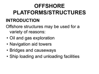

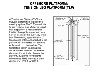
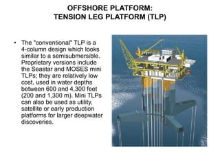
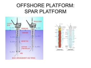
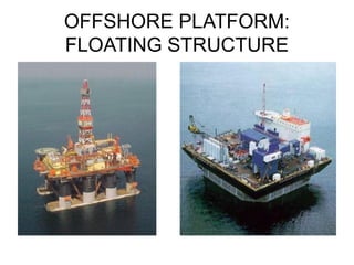
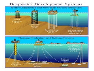
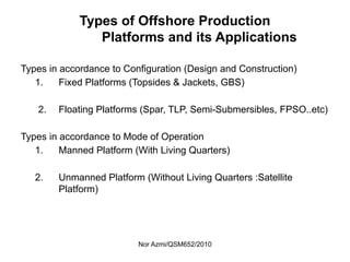
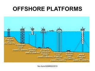
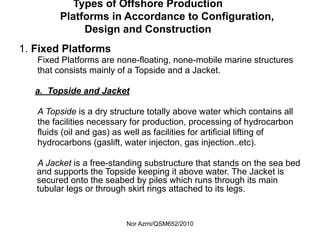
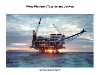
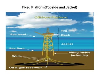
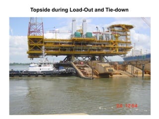
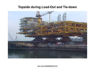
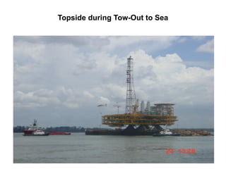
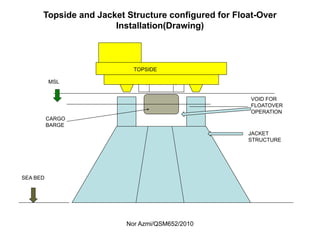
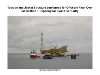
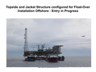
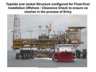
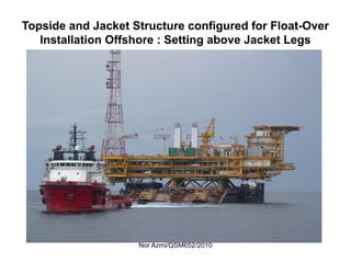
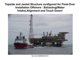
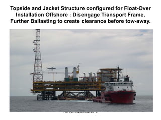
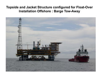
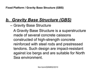
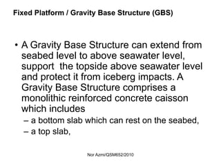
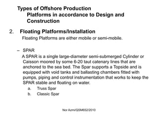
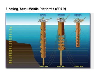
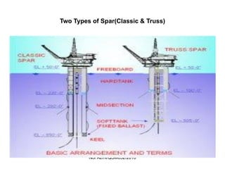
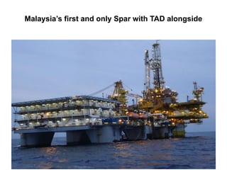
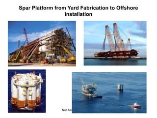
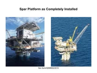
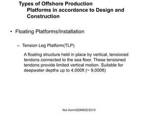
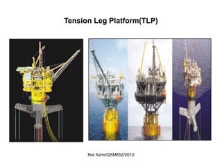
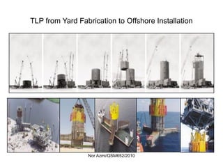
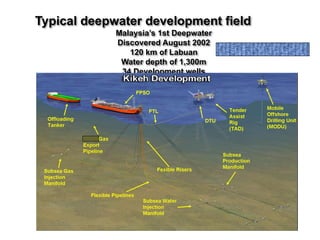
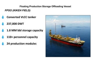
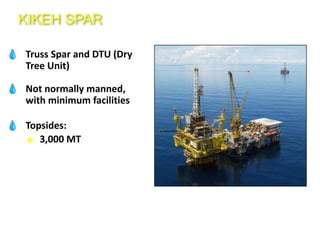
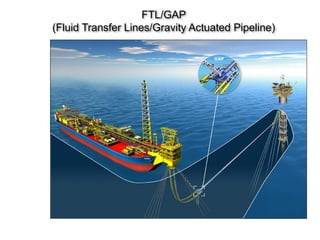
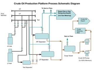
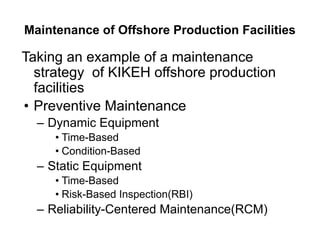

The document provides information on various types of offshore structures and platforms. It discusses fixed platforms, which include topsides and jackets structures, as well as gravity base structures. It also discusses floating platforms such as spar platforms, tension leg platforms, and semi-submersibles. Each type is chosen based on water depth considerations and the intended functions. The document also provides photos and diagrams to illustrate examples of different offshore structure types.


![[4] ptk 2014 2015 offshore constructions](https://cdn.slidesharecdn.com/ss_thumbnails/mhu59qizqiwfpndume0q-signature-e54dc48fc8dff231a3667ed370712382aa80c6605f7be8d156fba02fb451e6f5-poli-141027141817-conversion-gate01-thumbnail.jpg?width=640&height=640&fit=bounds)


