Use of pipelined ADCs is becoming increasingly popular both as stand alone parts and as embedded functional units in SOC design. They have acceptable resolution and high speed of operation and can be placed in relatively small area. The design is implemented in 0.18uM CMOS process. The design includes a folded cascode op-amp with a unity gain frequency of 200MHz at 88 deg. Phase margin and a dc gain of 75dB. The circuit employs a built in sample and hold circuit and a three phase non-overlapping clock.
This paper presents investigation and performance analysis of novel down sampling based clamping SV PWM technique for diode and cascaded Multi-level Invereter fed to Induction motor drive. A novel down sampling based clamping SVPWM has developed by adding triangular off set to sinusoidal fundamental waveform is modified by down sampling the reference wave by order of 10 so this technique is called clamping space vector pulse width modulation techniques such as PD, POD and APOD. so as to shift the lower order harmonics to higher order side. This novel carrier is compared with the offset injected space vector reference waveform to generate the required PWM pulses to the inverter. To analyze the performance of the proposed PWM technique it is implemented on seven level diode and cascaded Multi-level Inverter using Matlab/Simulink software tool for output line, phase voltage, currents, speed, torque and Total harmonic distortion analysis.
A 10-bit, 200MS/s CMOS Pipeline ADC using new shared opamp architecture VLSICS Design
A 10 bit opamp-sharing pipeline analog-to-digital converter (ADC) using a novel mirror telescopic operational amplifiers (opamp) with dual nmos differential inputs is presented. Reduction of power and area is achieved by completely merging the front-end sample-and-hold amplifier (SHA) into the first multiplying digital-to-analog converter (MDAC) using the proposed opamp. Transistors in the opamp are always biased in saturation to avoid increase of settling time due to opamp turn-on delays. The design targets 0.18um CMOS process for operation, at 200MS/s from a 1.8V supply. The simulation results show the SNDR and SFDR of 59.45dB and 68.69dB, respectively, and the power consumption of 35.04mW is achieved.
FAST TRANSIENT RESPONSE LOW DROPOUT VOLTAGE REGULATORijseajournal
This paper presents the design of Low Drop-Out (LDO) voltage regulator has fast transient response and which exploits a few current else low quiescent current in the operational amplifier PMOS type. We use band-gap reference for eliminate the temperature dependence. The proposed LDO voltage regulator implemented in 0.18-μm CMOS technology, we use Folded cascode CMOS amplifiers high performance in the stability , provide fast transient response which explains a fast settling, the LDO itself should provide in the output regulator voltages at t equal 2ps with transient variation of the voltage less than 170mV. High accuracy in the DC response terms, the simulation results show that the accuracy of the output regulator voltages is 1.54±0.009V, and power consumption of 1.51 mW.
Analysis and Design of A Low-Voltage Low-Power Double-Tail Comparator. This is a final semester Mtech project on VLSI design implementation of dual tail comparator in a modifyied version. This design is implemented using VHDL Language with 100% Source code synthesizable available. Software for free to download and knowledge transfer for the same project is also being implemented..The design is implemented using FSM technology, low power is achieved in this project.area utilization is the major advantage in this project.Low power techniques such as Clock gating, power gating is implemented in this project.,ieee reference paper is used for the base.
An improved design of CMOS dynamic latch comparator with dual input dual output with a simple
design of three stages is represented. The basic disadvantages of latch type comparators are overcome by
producing an edge triggered comparison. The circuit is designed for a resolution of 300nV and the power
consumption is reduced to 450uW. It is designed for 1.8V DC supply voltage and 1 MHz clock frequency for
PVT variations. The simulation of the comparator is done in Cadence® Virtuoso Analog Design Environment
using 180nm technology. The error quotient is reduced less than 5% by adding a buffer stage. The delay is
brought down to 5nS. The active area appreciably is reduced. Layout of the proposed comparator has been
simulated in Cadence® Virtuoso Layout XL Design Environment. DRC and LVS have been verified.
Minimum Mismatch of Current in Fully Differential Charge Pump for Integer N- ...IJERA Editor
Fully Differential ended charge pump (FDCP) are proven to have advantages over single ended charge pump at the cost of complexity and required more power for implementation for digital phase locked loop(DPLL). Wide swing cascodebias voltage with the rail to rail operational amplifier(opamp) as common mode feedback(CMFB) provides efficient solutions for current mismatch due to its non-idealities. The FDCP is simulated across process corners using 65nm technology with tsmc foundry for10Ghz DPLL. The power consumption of FDCP is 23mW with 100uA as Charge Pump (CP) current.
Design of Low Voltage Low Power CMOS OP-AMPIJERA Editor
Operational amplifiers are an integral part of many analog and mixed signal systems. As the demand for mixed
mode integrated circuits increases, the design of analog circuits such as operational amplifiers in CMOS
technology becomes more critical. This paper presents a two stage CMOS operational amplifier, which operates
at ±1.8V power supply using TSMC 0.18um CMOS technology. The OP-AMP designed exhibit unity gain
frequency of 12.6 MHz, and gain of 55.5db with 300uw power dissipation. The gain margin and phase margin
of OP-AMP is 45˚ and 60˚ respectively. Design and simulation has been carried out in P Spice tool.
Comparators are basic building elements for designing modern analog and mixed signal systems. Speed and resolution are two important factors which are required for high speed applications. This paper presents a design for an on chip high-speed dynamic latched comparator for high frequency signal digitization. The dynamic latched comparator consists of two cross coupled inverters comprising a total of 9 MOS transistors. The measured and simulation results show that the dynamic latched comparator design has higher speed, low power dissipation and occupying less active area compared to double tail latched and preamplifier based clocked comparators. A new fully dynamic latched comparator which shows lower offset voltage and higher load drivability than the conventional dynamic latched comparators has been designed. With two additional inverters inserted between the input-stage and output-stage of the conventional double-tail dynamic comparator, the gain preceding the regenerative latch stage was improved and the complementary version of the output-latch stage, which has bigger output drive current capability at the same area, was implemented.
Design of High-Speed Dynamic Double-Tail ComparatorIJERDJOURNAL
ABSTRACT:- The analog-to-digital converters which are of ultra low-power, area efficient, and high speed converters are made of dynamic regenerative comparators. These comparators can maximize speed and power efficiency. The delay and power dissipation of dynamic comparators are analyzed in this paper. The delays and tradeoff can be explored. The circuit of a conventional double tail comparator in this analysis is modified for fast operation even in different supply voltages. By using power gating technique and adding few transistors, the positive feedback during the regeneration is strengthened in the proposed comparator structure. The delay time can be reduced by providing positive feedback instead of adding few transistors. The analysis results are going to be confirmed on the basis of 0.25-µm CMOS technology. The power consumption and delay time can be significantly reduced based on this analysis. All the simulation are made using TANNER TOOLS, Generic 250nm. The schematic are drawn in the T-SPICE schematic editor.
An operational amplifier with recycling folded cascode topology and adaptive ...VLSICS Design
This paper presents a highly adaptive operational amplifier with high gain, high bandwidth, high speed
and low power consumption. By adopting the recycling folded cascode topology along with an adaptivebiasing
circuit, this design achieves high performance in terms of gain-bandwidth product (GBW) and slew
rate (SR). This single stage op-amp has been designed in 0.18μm technology with a power supply of 1.8V
and a 5pF load. The simulation results show that the amplifier achieved a GBW of 335.5MHz, Unity Gain
Bandwidth of 247.1MHz and a slew rate of 92.8V/μs.
A New Proposal for OFCC-based Instrumentation AmplifierIJECEIAES
This contribution puts forward a new voltage mode instrumentation amplifier (VMIA) based on operational floating current conveyor (OFCC). It presents high impedance at input terminals and provides output at low impedance making the proposal ideal for voltage mode operation. The proposed VMIA architecture has two stages - the first stage comprises of two OFCCs to sense input voltages and coverts the voltage difference to current while the second stage has single OFCC that converts the current to voltage. In addition it employs two resistors to provide gain and imposes no condition on the values of resistors. The behavior of the proposed structure is also analyzed for OFCC non idealities namely finite transimpedance and tracking error. The proposal is verified through SPICE simulations using CMOS based schematic of OFCC. Experimental results, by bread boarding it using commercially available IC AD844, are also included.
A New Proposal for OFCC-based Instrumentation AmplifierYayah Zakaria
This contribution puts forward a new voltage mode instrumentation amplifier (VMIA) based on operational floating current conveyor (OFCC). It presents high impedance at input terminals and provides output at low impedance making the proposal ideal for voltage mode operation. The proposed VMIA
architecture has two stages - the first stage comprises of two OFCCs to sense input voltages and coverts the voltage difference to current while the second stage has single OFCC that converts the current to voltage. In addition it employs two resistors to provide gain and imposes no condition on the values
of resistors. The behavior of the proposed structure is also analyzed for OFCC non idealities namely finite transimpedance and tracking error. The proposal is verified through SPICE simulations using CMOS based schematic of OFCC. Experimental results, by bread boarding it using commercially available IC AD844, are also included.
International Journal of Engineering Research and Applications (IJERA) is a team of researchers not publication services or private publications running the journals for monetary benefits, we are association of scientists and academia who focus only on supporting authors who want to publish their work. The articles published in our journal can be accessed online, all the articles will be archived for real time access.
Our journal system primarily aims to bring out the research talent and the works done by sciaentists, academia, engineers, practitioners, scholars, post graduate students of engineering and science. This journal aims to cover the scientific research in a broader sense and not publishing a niche area of research facilitating researchers from various verticals to publish their papers. It is also aimed to provide a platform for the researchers to publish in a shorter of time, enabling them to continue further All articles published are freely available to scientific researchers in the Government agencies,educators and the general public. We are taking serious efforts to promote our journal across the globe in various ways, we are sure that our journal will act as a scientific platform for all researchers to publish their works online.
Compact low power high slew-rate cmos buffer amplifier with power gating tech...VLSICS Design
A qualitative analysis of different parameters such as Phase noise, Slew rate and tranconductance by using
power gating reduction technique is presented. The circuit achieves the large driving capability by
employing simple comparators to sense the transients of the input to turn on the output stages, which are
statically off in the stable state. The effect of the different number of transistors and their topologies on the
phase noise and Slew rate is analyzed. Good agreement between qualitative and quantitative measurements
is observed. Scope of reducing of Noise and avoidance of Leakage due to various sources is discussed.
AN OPERATIONAL AMPLIFIER WITH RECYCLING FOLDED CASCODE TOPOLOGY AND ADAPTIVE ...VLSICS Design
This paper presents a highly adaptive operational amplifier with high gain, high bandwidth, high speed and low power consumption. By adopting the recycling folded cascode topology along with an adaptivebiasing circuit, this design achieves high performance in terms of gain-bandwidth product (GBW) and slew rate (SR). This single stage op-amp has been designed in 0.18µm technology with a power supply of 1.8V and a 5pF load. The simulation results show that the amplifier achieved a GBW of 335.5MHz, Unity Gain Bandwidth of 247.1MHz and a slew rate of 92.8V/µs.
The paper introduces a multi-pass loop voltage controlled ring oscillator. The proposed structure uses cross-coupled PMOS transistors and replica bias with coarse/fine control signal. The design implemented in TSMC 90 nm CMOS technology, 0.9V power supply with frequency tuning range 481MHz to 4.08GHz and -94.17dBc/Hz at 1MHz offset from 4.08GHz with 26.15mW power consumption.
A novel voltage reference without the operational amplifier and resistorsIJRES Journal
novel voltage reference has been proposed and simulated using a 0.18μm CMOS process in
this paper. A near-zero temperature coefficient voltage is achieved in virtue of the bias voltage subcirciut which
consists of two MOSFETs operating in the saturation region. The kind of bias voltage subcirciut is used to
adjust the output voltage and compensate the curvature. The output voltage is equal to the extrapolated
threshold voltage of a MOSFET at absolute zero temperature, which was about 591.5 mV for the MOSFETs we
used. The power supply rejection ratio (PSRR) is improved with three feedback loops. Although the output
voltage fluctuates with process variation, the circuit can monitor the process variation in MOSFET threshold
voltage. The simulation results show that the line regulation is 0.75 mV/V in a supply voltage range from 1.6 V
to 3.1 V and the temperature coefficient is around 10.8 ppm/℃ to 28.5 ppm/℃ at 9 different corners in a
temperature range from -20℃ to 120 ℃.
The PSRR is -70 dB at 100Hz with a supply voltage at 1.8 V, and the
layout size is 0.012mm2. The results of simulation and post layout simulation are almost the same.
This Analog Communication Lab Manual is prepared for JNTU, Hyderabad (in a general way to be utilized for the maximum institutions) for R18 regulation.
Low Power Low Voltage Bulk Driven Balanced OTA VLSICS Design
The last few decades, a great deal of attention has been paid to low-voltage (LV) low-power (LP) integrated circuits design since the power consumption has become a critical issue. Among many techniques used for the design of LV LP analog circuits, the Bulk-driven principle offers a promising route towards this design for many aspects mainly the simplicity and using the conventional MOS technology to implement these designs. This paper is devoted to the Bulk-driven (BD) principle and utilizing this principle to design LV LP building block of Operational Transconductance Amplifier (OTA) in standard CMOS processes and supply voltage 0.9V. The simulation results have been carried out by the Spice simulator using the 130nm CMOS technology from TSMC.
LOW POWER LOW VOLTAGE BULK DRIVEN BALANCED OTAVLSICS Design
The last few decades, a great deal of attention has been paid to low-voltage (LV) low-power (LP) integrated circuits design since the power consumption has become a critical issue. Among many techniques used for the design of LV LP analog circuits, the Bulk-driven principle offers a promising route towards this design for many aspects mainly the simplicity and using the conventional MOS technology to implement these designs. This paper is devoted to the Bulk-driven (BD) principle and utilizing this principle to design LV LP building block of Operational Transconductance Amplifier (OTA) in standard CMOS processes and supply voltage 0.9V. The simulation results have been carried out by the Spice simulator using the 130nm CMOS technology from TSMC.
Similar to A 80Ms/sec 10bit PIPELINED ADC Using 1.5Bit Stages And Built-in Digital Error Correction Logic (20)
COLLEGE BUS MANAGEMENT SYSTEM PROJECT REPORT.pdfKamal Acharya
The College Bus Management system is completely developed by Visual Basic .NET Version. The application is connect with most secured database language MS SQL Server. The application is develop by using best combination of front-end and back-end languages. The application is totally design like flat user interface. This flat user interface is more attractive user interface in 2017. The application is gives more important to the system functionality. The application is to manage the student’s details, driver’s details, bus details, bus route details, bus fees details and more. The application has only one unit for admin. The admin can manage the entire application. The admin can login into the application by using username and password of the admin. The application is develop for big and small colleges. It is more user friendly for non-computer person. Even they can easily learn how to manage the application within hours. The application is more secure by the admin. The system will give an effective output for the VB.Net and SQL Server given as input to the system. The compiled java program given as input to the system, after scanning the program will generate different reports. The application generates the report for users. The admin can view and download the report of the data. The application deliver the excel format reports. Because, excel formatted reports is very easy to understand the income and expense of the college bus. This application is mainly develop for windows operating system users. In 2017, 73% of people enterprises are using windows operating system. So the application will easily install for all the windows operating system users. The application-developed size is very low. The application consumes very low space in disk. Therefore, the user can allocate very minimum local disk space for this application.
Vaccine management system project report documentation..pdfKamal Acharya
The Division of Vaccine and Immunization is facing increasing difficulty monitoring vaccines and other commodities distribution once they have been distributed from the national stores. With the introduction of new vaccines, more challenges have been anticipated with this additions posing serious threat to the already over strained vaccine supply chain system in Kenya.
Final project report on grocery store management system..pdfKamal Acharya
In today’s fast-changing business environment, it’s extremely important to be able to respond to client needs in the most effective and timely manner. If your customers wish to see your business online and have instant access to your products or services.
Online Grocery Store is an e-commerce website, which retails various grocery products. This project allows viewing various products available enables registered users to purchase desired products instantly using Paytm, UPI payment processor (Instant Pay) and also can place order by using Cash on Delivery (Pay Later) option. This project provides an easy access to Administrators and Managers to view orders placed using Pay Later and Instant Pay options.
In order to develop an e-commerce website, a number of Technologies must be studied and understood. These include multi-tiered architecture, server and client-side scripting techniques, implementation technologies, programming language (such as PHP, HTML, CSS, JavaScript) and MySQL relational databases. This is a project with the objective to develop a basic website where a consumer is provided with a shopping cart website and also to know about the technologies used to develop such a website.
This document will discuss each of the underlying technologies to create and implement an e- commerce website.
Democratizing Fuzzing at Scale by Abhishek Aryaabh.arya
Presented at NUS: Fuzzing and Software Security Summer School 2024
This keynote talks about the democratization of fuzzing at scale, highlighting the collaboration between open source communities, academia, and industry to advance the field of fuzzing. It delves into the history of fuzzing, the development of scalable fuzzing platforms, and the empowerment of community-driven research. The talk will further discuss recent advancements leveraging AI/ML and offer insights into the future evolution of the fuzzing landscape.
Saudi Arabia stands as a titan in the global energy landscape, renowned for its abundant oil and gas resources. It's the largest exporter of petroleum and holds some of the world's most significant reserves. Let's delve into the top 10 oil and gas projects shaping Saudi Arabia's energy future in 2024.
Hybrid optimization of pumped hydro system and solar- Engr. Abdul-Azeez.pdffxintegritypublishin
Advancements in technology unveil a myriad of electrical and electronic breakthroughs geared towards efficiently harnessing limited resources to meet human energy demands. The optimization of hybrid solar PV panels and pumped hydro energy supply systems plays a pivotal role in utilizing natural resources effectively. This initiative not only benefits humanity but also fosters environmental sustainability. The study investigated the design optimization of these hybrid systems, focusing on understanding solar radiation patterns, identifying geographical influences on solar radiation, formulating a mathematical model for system optimization, and determining the optimal configuration of PV panels and pumped hydro storage. Through a comparative analysis approach and eight weeks of data collection, the study addressed key research questions related to solar radiation patterns and optimal system design. The findings highlighted regions with heightened solar radiation levels, showcasing substantial potential for power generation and emphasizing the system's efficiency. Optimizing system design significantly boosted power generation, promoted renewable energy utilization, and enhanced energy storage capacity. The study underscored the benefits of optimizing hybrid solar PV panels and pumped hydro energy supply systems for sustainable energy usage. Optimizing the design of solar PV panels and pumped hydro energy supply systems as examined across diverse climatic conditions in a developing country, not only enhances power generation but also improves the integration of renewable energy sources and boosts energy storage capacities, particularly beneficial for less economically prosperous regions. Additionally, the study provides valuable insights for advancing energy research in economically viable areas. Recommendations included conducting site-specific assessments, utilizing advanced modeling tools, implementing regular maintenance protocols, and enhancing communication among system components.
Forklift Classes Overview by Intella PartsIntella Parts
Discover the different forklift classes and their specific applications. Learn how to choose the right forklift for your needs to ensure safety, efficiency, and compliance in your operations.
For more technical information, visit our website https://intellaparts.com
Explore the innovative world of trenchless pipe repair with our comprehensive guide, "The Benefits and Techniques of Trenchless Pipe Repair." This document delves into the modern methods of repairing underground pipes without the need for extensive excavation, highlighting the numerous advantages and the latest techniques used in the industry.
Learn about the cost savings, reduced environmental impact, and minimal disruption associated with trenchless technology. Discover detailed explanations of popular techniques such as pipe bursting, cured-in-place pipe (CIPP) lining, and directional drilling. Understand how these methods can be applied to various types of infrastructure, from residential plumbing to large-scale municipal systems.
Ideal for homeowners, contractors, engineers, and anyone interested in modern plumbing solutions, this guide provides valuable insights into why trenchless pipe repair is becoming the preferred choice for pipe rehabilitation. Stay informed about the latest advancements and best practices in the field.
TECHNICAL TRAINING MANUAL GENERAL FAMILIARIZATION COURSEDuvanRamosGarzon1
AIRCRAFT GENERAL
The Single Aisle is the most advanced family aircraft in service today, with fly-by-wire flight controls.
The A318, A319, A320 and A321 are twin-engine subsonic medium range aircraft.
The family offers a choice of engines
A 80Ms/sec 10bit PIPELINED ADC Using 1.5Bit Stages And Built-in Digital Error Correction Logic
1. International Journal of VLSI design & Communication Systems (VLSICS) Vol.2, No.3, September 2011
DOI : 10.5121/vlsic.2011.2303 39
A 80Ms/sec 10bit PIPELINED ADC Using 1.5Bit
Stages And Built-in Digital Error Correction Logic
P.Prasad Rao1
and Prof.K.Lal Kishore2
,
1
Research Scholar, JNTU-Hyderabad
prasadrao_hod@yahoo.co.in
2
Director, R&D, JNTU-Hyderabad
lalkishorek@yahoo.com
Abstract
Use of pipelined ADCs is becoming increasingly popular both as stand alone parts and as embedded
functional units in SOC design. They have acceptable resolution and high speed of operation and can be
placed in relatively small area. The design is implemented in 0.18uM CMOS process. The design includes a
folded cascode op-amp with a unity gain frequency of 200MHz at 88 deg. Phase margin and a dc gain of
75dB. The circuit employs a built in sample and hold circuit and a three phase non-overlapping clock.
Keywords
ADC, 1.5 bit stage, CMFB, Pipeline, Redundancy bit removal algorithm
1. INTRODUCTION
High resolution, high speed CMOS ADCs are used for scanners, high definition TVs, medical
equipment, camcorders and radar systems and are limited to 10 bits because of various reasons. In
this work, a fully differential 10 bit ADC was implemented using an inherent digital error
correction technique. The fully differential Folded Cascode op-amp architecture is used. Power
dissipation in op-amp can be reduced by reducing either supply voltage or total current in the
circuit or by reducing the both[10]. As the input current is lowered though power dissipation is
reduced, the dynamic range is degraded. As the supply voltage decreases, it also becomes
increasingly difficult to keep transistors in saturation with the voltage headroom available. The
design takes care of power optimization at every level of design. The block diagram of general
Pipelined ADC is shown in Fig. (1). Each stage contains a S/H circuit, a low resolution A/D
subconverter, a low resolution D/A converter and a differencing fixed gain amplifier. Flash and
subranging architectures need exponential rather than linear increase in area to increase their
resolution and also require trimming and calibration. But for pipelined converters, area is small
and is linearly related to the resolution because the resolution can be increased by adding stages
to the end of the pipeline without increasing the number of clock phases required per conversion.
2. OP-AMP REQUIREMENTS FOR ADCS
The typical gain and phase responses of an op-amp are shown in fig.(2). The bandwidth and gain
characteristics are crucial in the design of data converters. The op-amp is preferred to have 90o
2. International Journal of VLSI design & Communication Systems (VLSICS) Vol.2, No.3, September 2011
40
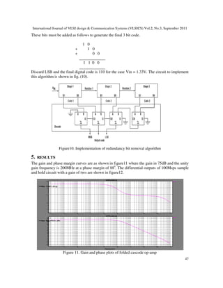
phase margin over full load conditions and process variations to avoid second order step response
and its associated ringing.
Figure 1. Block diagram of pipelined ADC
Decreasing the phase margin results in an increase of amplitude of ringing and this can
increase the settling time. It can be proved that the DC open loop gain of an op-amp used in an
ADC must satisfy the condition[1]
Aol >= 2 N+2
Where N is the no. of bits of conversion. For example a 10 Bit data converter needs a minimum
DC open loop gain of 212
. The speed of an op-amp is decided by the op-amp used. The minimum
unity gain frequency (fu ) for a given settling time ( ts < 1/fclk ) required to settle the output to
within + ½ LSB of its final value can be evaluated as[1]
fu >= 0.22 (N+1) fclk_
i.e. for a 10 bit ADC at 80 MHz clock frequency needs an op-amp with a unity gain frequency of
around 200 MHz.
Figure 2. Magnitude and phase response of an op-amp
3. International Journal of VLSI design & Communication Systems (VLSICS) Vol.2, No.3, September 2011
41
2.1. Folded Cascode Op-Amp
Modern integrated CMOS op-amps are designed to drive capacitive loads[7][8]. With only a
capacitive load it is not necessary to use a buffer at the output for a low impedance node.
Therefore, it is possible to design op-amps at higher speeds and larger voltage swings than those
which drives resistive loads. These improvements are achieved with a single high impedance
node at the output that drives only capacitive loads. For folded cascode op-amps the
compensation is achieved by CL itself and it is dominant pole compensation. As CL increases, the
op-amp stability improves but is slowed down. The folded cascode op-amp schematic is shown in
Fig. ( 3 ).
Figure 3. Fully differential folded cascode op-amp
The basic idea of folded cascode op-amp is to apply the opposite type PMOS cascode transistors
to the input differential pair of NMOS type. This arrangement allows the output to be taken at the
same bias levels as that of input signal. Even though it is a single stage, the gain is reasonable
since the gain is decided by the product of input transconductance and the large output
impedance. Applying AC input voltage vin causes the drain of differential stage to be gmvin. This
AC drain current is mirrored in the cascaded MOSFETs M7-M12.the output voltage of folded
cascode is then
Vout = gm vin Rout . Where
Rout = [ ( R looking back into the drain of M10 ) II
(R looking into the drain of M8 )].
=[ rout10 ( 1 + gm10 rout12 )] II [ rout8 ( 1 + gm8rout6)]
The gain of folded cascode op-amp is then
A = vout / vin = gm Rout. ………. ( 1 )
The dominant pole of the op-amp is at 1 / 2 ∏ Rout CL.
Parasitic poles exist at M7/M8 & M9/M10 combination. These parasitic poles must be larger than
the unity gain frequency of the op-amp given by
Fu = gm / 2 ∏ CL. ……. ( 2 )
4. International Journal of VLSI design & Communication Systems (VLSICS) Vol.2, No.3, September 2011
42
For the required unity gain frequency and for a given transistor gm, CL is evaluated using eq. (2).
2.2. Biasing circuit
The bias voltages are generated using the circuit shown in fig. (4). The circuit basically has two
wide swing current mirrors. M1 and M2 are sized ¼ of the size of other MOSFETs. If current
through resistor, I = 5uA, then this biasing scheme results in 5uA to flow in M13 and M14 of
figure 3. MOSFETs M1, M2 and M7-M12 will carry 5 uA of drain current. MOSFETs M5/M6
must now carry 7.5 uA. This biasing scheme gives maximum swing at the drains of M8/M10. The
currents in M5-M6 are 7.5uA. The CMFB circuit must adjust the gate drive of M5 and M6 so that
they provide 7.5 uA of current in them.
Figure 4. Biasing circuit for the folded cascode op-amp
2.3. CMFB circuit
The common mode feedback circuit is shown in figure 5.
Figure 5. The CMFB circuit
5. International Journal of VLSI design & Communication Systems (VLSICS) Vol.2, No.3, September 2011
43
Here, the output of folded cascode op-amp, vo+ and vo- are the inputs to the CMFB circuit while
the output is Vcmfb. This circuit rejects the difference mode signal at its input and amplifies the
common mode signal. This is exactly opposite to that of a differential amplifier.
The expression for output is
Vcmfb = A[ ( vo+ + vo- ) / 2 – Vcm ]
In the circuit, if vout+ and vout- goes above Vcm, then drain currents of MC6 & MC7 starts to
decrease. This makes Vcmfb to increase towards Vdd. This increase in Vcmfb will make the drain
currents of M5/M6 of fig (3) to decrease. Since currents in M9 to M12 are constant, it results in a
decrease of vo+ and vo-. Similar arguments can be made if vo+ and vo- goes below Vcm.
Figure 6 shows a fully differential S/H implementation using an op-amp or an OTA. At t = t0, the
switches Φ1 and Φ2 are closed while Φ3 switches are open. During t1 → t2 duration, the input
voltage charges the capacitor CH.
3. SAMPLE AND HOLD CIRCUIT
Figure 6. Fully differential sample and hold circuit
At t1, the switch Φ1 opens and for a very short duration t3→t1, the op-amp is in open loop [2] [5].
As the top plate of CH is at gnd, the charge injection and capacitive feed through resulting from
turning OFF of Φ3 switches becomes independent of input signal. When Φ2 switch turns OFF,
the charge injection will flow into the low impedance vin and not into the right side of Φ2 as this
impedance is large. This leaves the voltage across capacitor unaffected by the charge injection
resulting from the turning OFF of the switches. This sequence of turning OFF of the switches is
called bottom plate sampling. The fully differential Sample and Hold implementation is shown in
fig. (7). We can determine the input/output relationship of sample and hold circuit by evaluating
6. International Journal of VLSI design & Communication Systems (VLSICS) Vol.2, No.3, September 2011
44
the charge stored on Ci and Cf. Initially, assuming Vci+ and Vci- are combined and connected to
a common voltage Vcm, we have
When Φ1 and Φ 2 switches are closed and Φ3 open then the charge on Ci and Cf
Qi, f = Ci, f ( vin – vcm + voffset )
Figure 7. Fully differential S/H circuit implementation
When Φ 3 goes high, the charge on Ci is
Qin = Ci ( vcm – vcm +- voffset )
The difference between Qin (when Φ1 is ON ) and Qin ( when Φ3 is ON is transferred to Cf
when Φ3 goes high. Since the charge must be conserved,
Cf ( vout – vcm ± voffset ) = C f ( vin – vcm ± voffset ) + Ci ( vin – vcm ± voffset )
+ Ci ( vcm – vcm ± voffset )
OR when Φ3 is on,
Vout = [ 1+ Ci / Cf] vin – Ci / Cf vcm …. ( 3 )
Notice that the op-amp offset is automatically zeroed out.
Eq. 3 can be used to find the relation of vin and vout for fully differential signals given by
Vout = (vout+ - vout-) = (1+ Ci / Cf) (vin+ - vin-)
7. International Journal of VLSI design & Communication Systems (VLSICS) Vol.2, No.3, September 2011
45
Notice that the common mode voltage subtracts out.
If vcm is replaced by Vci+ and Vci- as shown in figure 8, then
Vout+ = (1+ Ci / Cf) vin+ - Ci / Cf Vci+ and
Vout = (vout+ - vout-) = (1+ Ci / Cf) (vin+ - vin-) - Ci / Cf (Vci+ - Vci-)
Figure 8. Implementing subtraction in S/H
4. 1.5 BITS / STAGE
Pipelined ADCs get their final resolution using a series of cascaded lower resolution stages
[3][8][9]. For example, a 12 bit ADC can be a cascade of four 3-bit stages. Many designers are
comfortable with 3-bit flash ADCs. However, 1.5 bits / stage is also becoming increasingly
popular. For high speed converters there is an advantage of going for minimum stage resolution.
It minimises the interstage gain required, which in turn maximises the bandwidth, since gain
bandwidth product is a constant for a given technology.
A 1.5 bits/stage is a 1bit/stage into which some redundancy is added to provide for device
tolerances and imperfections. A digital error correction later eliminates this redundancy. The
1.5bits/stage uses two analog comparison levels Vu & VL instead of a single level in a 1
bit/stage. Because of the introduction of gain of two, they must lie between –Vref/2 and +Vref/2.
a common choice is Vu = +Vref/4 and VL = – Vref/4.
The voltage transfer characteristic is shown in fig. 9 (b) which is highly nonlinear.
The input voltage range is divided into three sections. The upper range (U) above Vu, mid range
between Vu and VL and low range (L) below VL as shown in the table 1.
Table1.
Vin Range B1 B0 DAC o/p Analog residue o/p
Vin > Vu U 1 0 + Vref 2Vin – Vref
VL<Vin< Vu M 0 1 0 2Vin
Vin < VL L 0 0 - Vref 2Vin + Vref
8. International Journal of VLSI design & Communication Systems (VLSICS) Vol.2, No.3, September 2011
46
The implementation of 1.5bits/stage is shown in fig. 9 ( a ). A resistor string provides voltage
division to create reference voltages. All other high accuracy operations such as multiply-by-two
are achieved by capacitor ratios. The sample and hold circuit and multiply-by-two amplifier can
be combined to form a multiplying DAC ( MDAC ). The cascaded MDAC outputs are passed
through latches before fed to the redundancy bit removal circuit as shown in figure11.
4.1. Redundancy bit removal algorithm
The probable error sources in data converters include offset voltages in comparators and op-amps,
gain error in amplifier, nonlinearity in converter and others. Many of these errors are corrected by
this algorithm[8][9].
Figure 9. (a) A 1.5 bit pipelined ADC stage. (b)The stage voltage transfer characteristic.
Each 1.5bit pipelined stage produces a 2 bit code B1B0. Using redundancy bit removal algorithm,
this is reduced to final 1 bit per stage code. For a resolution of 3 bits, the input voltage range of
+2V is divided into 8 equal slots and the input voltage, the code generation of each stage and
corresponding stage residue voltages are shown in table 2. To generate the final code, the two bit
codes generated by each stage are added in a systematic way. For example, as highlighted in table
2, for Vin = 1.33V, the codes generated by successive stages are 10, 10 and 00.
Table 2. Development of error corrected output code
9. International Journal of VLSI design & Communication Systems (VLSICS) Vol.2, No.3, September 2011
47
These bits must be added as follows to generate the final 3 bit code.
1 0
+ 1 0
+ 0 0
_____________
1 1 0 0
_____________
Discard LSB and the final digital code is 110 for the case Vin = 1.33V. The circuit to implement
this algorithm is shown in fig. (10).
Figure10. Implementation of redundancy bit removal algorithm
5. RESULTS
The gain and phase margin curves are as shown in figure11 where the gain in 75dB and the unity
gain frequency is 200MHz at a phase margin of 880
. The differential outputs of 100Msps sample
and hold circuit with a gain of two are shown in figure12.
Figure 11. Gain and phase plots of folded cascode op-amp
10. International Journal of VLSI design & Communication Systems (VLSICS) Vol.2, No.3, September 2011
48
Figure 12. Sample and Hold outputs
The input signals are 0.5V differential and the output is seen to be 2V i.e. the differential
input signals are sampled and given a gain of 2.The INL and DNL errors are observed to be
less than ½ LSB as in figure13.
Figure13. INL and DNL error
REFERENCES
[1] R. Jacob Baker, CMOS mixed signal circuit design, 2nd ed., IEEE press, 2003.
[2] Rudy van de Plassey., CMOS Analog-toDigital and Digital-to-analog Converters, : Springer, 2005.
[3] David A Johns and Ken Martin, Analog integrated circuit design., 2005.
11. International Journal of VLSI design & Communication Systems (VLSICS) Vol.2, No.3, September 2011
49
[4] Behzad Razavi, Design of Analog CMOS Integrated circuits,TMH 2002.
[5] Jipeng Li and Un-Ku Moon, “A 1.8V 67mW 10bit 100 M/S Pipelined ADC using time shifted CDS
technique,” IEEE J solid state circuits,vol 39 pp. 1468-1476, September 2004.
[6] Thomas Byunghak Cho, Paul R.Gray, “A 10b, 20 Msample/s, 35 mW Pipeline A/D Converter”,
IEEE Journal of Solid State Circuits, Vol. 30, No.3, March 1995
[7] Byung-Moo Min, Peter Kim, Frederick W. Bowman, David M. Boisvert, “A 69 mW 10 bit 80 Msps
Pipelined CMOS ADC”, IEEE Journal of Solid State Circuits, Vol. 38, No.12, December 2003.
[8] Hung-Chih Liu, Zwei-Mei Lee, Jieh-Tsorng Wu, “a 15b 20MS/s CMOS Pipelined ADC with Digital
background Calibration”, ISSCC 2004.
[9] Ming-Huang Liu, Kuo-Chan Huang, Wei-Yang Ou, Tsung-Yi Su, Shen-Iuan Liu, “A Low Voltage-
Power 13 bit 16 MSPS CMOS Pipelined ADC”, IEEE Journal of Solid State Circuits, Vol. 39, No.5,
May 2004.
[10] Ratul Kr. Baruah, “ Design of Low power low voltage CMOS opamp”, International Journal of VLSI
design & Communication Systems (VLSICS) vol.1 N0.1 March 2010.
Authors
Mr.P.Prasad Rao is research Scholar in JNT University, Hyderabad and having more
than 19 years of teaching experience. He is presently working as an
Associate Professor at SR Engineering College, Warangal, AP. He was
Awarded Fellowship in VLSI Design twice in 2006 & 2007. He has published
papers in many national conferences and in international journal. Mr.P.Prasad Rao
has post-Graduate Degree in VLSI System Design from National Institute of
Technology, Warangal.
Prof. K. Lal Kishore is a Senior Professor in Electronics and Communications
Engg., Department of JNTUH University, Hyderabad and is presently the Director,
R & D Cell. He has more than 114 Research Publications to his credit. He has
produced Six Ph.Ds and many more Research Scholars are working under his
Guidance. He has over 33 years of Experience in Teaching and Research. Prof. K.
Lal Kishore has Post-Graduate and Ph.D Degrees from Indian Institute of Science
(I.I.Sc) Bangalore. He had held number of administrative positions in the University
including that of Rector, Registrar, Director, Academic and
Planning, Director, School of IT, Principal JNTUH etc.