This document presents a 5-level three-phase cascaded hybrid multilevel inverter. It consists of a standard 3-leg inverter with an H-bridge connected in series to each leg, using separate DC voltage sources of 24V and 48V. The control signals are generated using a FPGA controller with PWM modulation. A simulation model was developed in PSCAD/EMTDC. Experimental results show the output voltages have 5 levels with THD between 15.6-18.3% and the output currents are close to sinusoidal with THD between 2.7-4.2%. The hybrid multilevel inverter topology reduces the number of switches and capacitors compared to other multilevel inverter structures.
![Abstract—This paper presents a 5-level three-phase cascaded
hybrid multilevel inverter that consists of a standard 3-leg (one
leg for each phase) and H-bridge in series with each inverter leg
with separate DC voltage sources, 24V and 48V. The control
signals for this hybrid multilevel inverter are implemented by a
FPGA controller using PWM signal modulated technique and
digital technique. A 5-level three-phase cascaded hybrid
multilevel inverter model based on PSCAD/EMTDC is
presented in this paper. The proposed hybrid multilevel
inverter is described in detail that it is verified experimentally
in three types of load; 18W fluorescent lamp-ballast, RL, and
1HP 3-phase induction motor; without filtering. Results of the
experiment; the output waveform of line-line and phase
voltages has 5 levels that percent of THD is between 15.6% and
18.3%, the output waveform of phase current is close to
sinusoidal that percent of THD is between 2.7% and 4.2%.
Index Terms—Hybrid multilevel inverter, PSCAD/EMTDC,
FPGA controller, h-bridge.
I. INTRODUCTION
A multilevel inverter is a power electronic converter built
to synthesize a desired AC voltage from several levels of DC
voltages which the DC levels were considered to be identical
in that all of them were batteries, solar cells, capacitors, etc.
The multilevel inverter has gained much attention in recent
years due to its advantages in lower switching loss better
electromagnetic compatibility, higher voltage capability, and
lower harmonics [1]-[3]. Several topologies for multilevel
inverters have been proposed; the most popular being the
diode-clamped [4], [5], flying capacitor [6], and cascade H-
bridge [7] structures. Besides the three basic multilevel
inverter topologies; other multilevel converter topologies
have been proposed, most of these are hybrid circuits that are
combinations of two of the basic multilevel topologies. The
schemes of multilevel inverters are classified in to two types
the multicarrier sub-harmonic pulse width modulation (MC-
SH PWM) and the multicarrier switching frequency optimal
pulse width modulation (MC-SFO PWM) [8], [9]. The
MC-SH PWM cascaded multilevel inverter strategy reduced
total harmonic distortion and the MC-SFO PWM cascade
multilevel inverter strategy enhances the fundamental output
voltage [10].
The THD will be decreased by increasing the number of
levels. It is obvious that an output voltage with low THD is
Manuscript received August 4, 2011; revised September 31, 2011.This
work was supported by the Department of Electrical Engineering, Faculty of
Engineering at Si Racha, Kasetsart University Si Racha Campus, and
Thailand.
P. Thongprasri is with the Department of Electrical Engineering, Faculty
of Engineering at Si Racha, Kasetsart University Si Racha Campus,
Chonburi, Thailand (e-mail: sfengprt@ src.ku.ac.th).
desirable, but increasing the number of levels needs more
hardware, also the control will be more complicated. It is a
tradeoff between price, weight, complexity and a very good
output voltage with lower THD. Fig. 1 shows single phase
topology of the diode Clamped, flying capacitor, a cascaded
H-bridge, and cascade hybrid multilevel inverter that they
have the number of switches, diodes, and capacitors as shown
in table I (a 5- level multilevel inverter).
dcV
1S
2S
3S
4S
5S
6S
7S
8S
oV
1C
2C
3C
4C
dcV
1S
2S
3S
4S
5S
6S
7S
8S
1C
2C
3C
4C
5C
6C
7C
8C
9C
10C oV
(a) Diode Clamped (b) Flying capacitor
multilevel inverter multilevel inverter
dcV
dcV
1S 2S
3S 4S
5S 6S
7S 8S
oV
2
dcV
dcV
1S 2S
3S 4S
5S
oV
6S
1C
2C
(c) Cascaded H-bridge (d) Cascaded Hybrid
multilevel inverter multilevel inverter
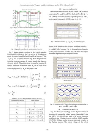
Fig. 1. One phase of a 5-level multilevel inverter.
TABLE I: COMPONENTS OF ONE PHASE OF A-5 LEVEL
MULTILEVEL INVERTER
Types of multilevel
inverter
Number of
switches
Number of
diodes
Number of
capacitors
Diode Clamped 8 12 4
Flying capacitor 8 - 10
Cascaded H-bridge 8 - -
Cascade hybrid 6 - 2
In this paper, the proposed a 5-level three-phase cascaded
hybrid multilevel inverter includes a standard 3-leg inverter
(one leg for each phase) and H-bridge in series with each
inverter leg as shown in Fig. 2. To develop the model of a
5-level cascaded hybrid multilevel inverter, a simulation is
done based on PSCAD/EMTDC. All signals for controlling
the hybrid multilevel inverter are created by a FPGA
controller using PWM signal modulated technique and digital
technique. The prototype is tested with 3 types of load; a 18W
fluorescent lamp-ballast, RL (R is 265 Ω , L is 0.125 H ),
and a 1HP 3-phase induction motor (no load); without
filtering.
A 5-Level Three-Phase Cascaded Hybrid
Multilevel Inverter
P. Thongprasri
International Journal of Computer and Electrical Engineering, Vol. 3, No. 6, December 2011
789](https://image.slidesharecdn.com/1-140819011751-phpapp02/85/1-1-320.jpg)
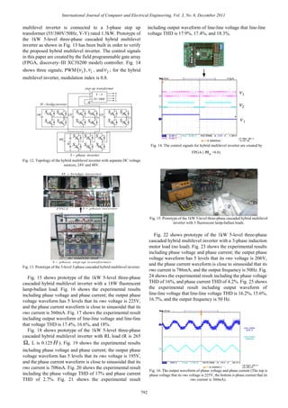
![II. OPERATION PRINCIPLE OF
THE HYBRID MULTILEVEL INVERTER
1aS
2aS
3aS
4aS
1bS
2bS
3bS
4bS
1cS
2cS
3cS
4cS
LOAD
aV
bV
cV
dcV 1S
2S
3S
4S
5S
6S
2
dcV
2
dcV
2
dcV
Fig. 2. Topology of a 5-level three-phase cascaded hybrid
multilevel inverter.
Fig. 2 shows the topology of the proposed a 5-level
3-phase cascaded hybrid multilevel inverter. Single phase
topology of the hybrid multilevel inverter is shown in Fig. 3;
the bottom is one leg of a standard 3-leg inverter with a dc
power source ( dcV ), the top is a hybrid in series with each
standard inverter leg that the H-bridge inverter can use a
separate dc power source ( 2/dcV ). Considering the output
voltage 1v of this leg is either 2/dcV+ when 1S closed or
2/dcV− when 2S closed. This leg is connected in series with
a full H-bridge inverter, then the output voltage 2v of the
H-bridge inverter is either 2/dcV+ when 41, aa SS closed, 0
when 31, aa SS or 42, aa SS closed, or 2/dcV− when 32, aa SS
closed. An example output waveform that this topology can
achieve as shown in the Fig. 4, when the output voltage
21 vvv += is required to be zero, one can either set
2/1 dcvv += and 2/2 dcvv −= or 2/1 dcvv −= , and 2/2 dcvv += .
In [11], several different two-level multilevel carrier-based
PWM techniques have been extend for controlling the active
devices in a multilevel converter, the most popular and
easiest technique to implement uses several triangle carrier
signals and one reference, or modulation, signal per phase. In
order to achieve better dc link utilization at high modulation
indices, the sinusoidal reference signal can be injected by a
third harmonic with a magnitude equal to 25% of
fundamental.
Fig. 5 shows MC-SH PWM of a 5-level inverter, m-1
carriers with the same frequency cf and the same amplitude
cA are dispose such that the bands they occupy are
contiguous, The reference waveform has peak-to-peak
amplitude mA , a frequency mf , and its zero centered in the
middle of the carrier set, The reference is continuously
compared with each of the carrier signals. If the reference is
greater than a carrier signal, then the active device
corresponding to that carrier is switched on, and if the
reference is less than a carrier signal, then the active device
corresponding to that carrier is switched off.
2
dcV
1aS
2aS
3aS
4aS
dcV
1S
2S
1v
2v
i
v
Fig. 3. Single phase topology of the hybrid multilevel inverter.
21 vvv +=
i
dcv+
dcv−
2/dcv+
π π2
2/dcv−
Fig. 4. Output waveform of the hybrid multilevel inverter.
Fig. 6 shows the relationship between the sinusoidal
reference signal and the triangular signal which used to create
the PWM signal; the output of the PWM signal is either 1,
when trictrl VV > or 0 when, trictrl VV < , and the PWM signal
width can be written as equation (1).
10; ≤≤⋅= ctrltrictrlPWM ATAT (1)
Nomenclature:
PWMT Width of the PWM signal.
ctrlA Height of the control signal.
triT Period of the triangular signal.
ctrlV Output voltage of the control signal.
triV Output voltage of the triangular signal.
0
1
2
2−
1−
Fig. 5. MC-SH PWM of a 5-level inverter.
Fig. 6. The relationship between the sinusoidal referencesignal and the
triangular signal.
0
controlV triV
trictrl VV >
PWM
rA
triT
ctrlT
0
1
International Journal of Computer and Electrical Engineering, Vol. 3, No. 6, December 2011
790](https://image.slidesharecdn.com/1-140819011751-phpapp02/85/1-2-320.jpg)

![APPENDIX
Fig. 26. The simulation model of a 5-level three- phase cascaded
multilevel inverter based on pscad/emtdc (single phase).
ACKNOWLEDGMENT
The author would like to thank the Faculty of
Engineering at Si Racha, Kasetsart University Si Racha
Campus, THAILAND, for instrument support on this
research.
REFERENCES
[1] J. S. Lai and F. Z. Peng, “Multilevel converters – A new breed of
power converters,” IEEE Trans. Ind. Applica, vol. 32, no. 3, pp.
509-517, May/June 1996.
[2] L. M. Tolbert, F. Z. Peng, and T. G. Habetler, “Multilevel
converters for large electric drives,” “IEEE Trans. Ind. Applica.”,
vol.35, no.1, pp. 36-44, Jan./Feb.1999.
[3] K. A. Corzine, M. W. Wielebski, F. Z. Peng, and J. Wang, “Control
of Cascaded Multilevel Inverters,” IEEE Trans. power electron,
vol.19, no.3, pp. 732-738, May 2004.
[4] M. Fracchia, T. Ghiara, M. Marchesoni, and M. Mazzucchelli,
“Optimized modulation techniques for the gemeralized N-level
converter,” in proc. IEEE power electronics specialist conf,
1205-1213, Madrid, Spain, 1992.
[5] K. A. Corzine and J. R. Baker, “Reduced parts-count multilevel
retifiers,” “IEEE Trans. Ind. Electron.” vol.49, no.3, pp. 766-774,
Aug. 2002.
[6] F. Z. Peng, “A generalized multilevel inverter topology with self
voltage balancing,” “IEEE Trans. Ind. Applica,” vol. 37, pp.
611-618, Mar./April 2004.
[7] M. D. Manjrekar, P. K. Steimer, and T. A. Lipo, “Hybrid
multilevel power conversion system: a competitive solution for
high-power applications,” “IEEE Trans. Ind. Applica,” vol. 36, pp.
834-841, May/June 2000.
[8] L. M. Tolber and T. G. Habetler, “Novel Multilevel Inverter
Carrier based PWM Method,” IEEE Trans. Ind. Applic, vol. 35,
pp. 1098-1107, Sep/Oct 1999.
[9] B. P.McGrath and Holmes, “Multicarrier PWM strategies for
multilevel inverter,” IEEE Trans. Ind. Electron, vol. 49, no. 4, pp.
834-841, Aug 2002.
[10] A. M.Hava, R. J.Kerman, and T.A.Lipo “Carrier-based PWM-VSI
Overmodulation Strategies: Analysis, Comparison, and Design,”
IEEE Trans. Power Electron, vol. 13, no. 4, pp. 834-841, Jul.
1998.
[11] S. Khomfoi, L. M. Tolbert, “Multilevel Power Converters,” “2nd ed.
Power Electronics Handbook,” Elsevier, 2007, ch. 31, pp. 1-50.
P. Thongprasri was born in Suphanburi,
Thailand, on June 19, 1971. He received the
B.Eng. degree in electronic engineering and
M.Eng. degree in electrical Engineering from
King Mongkut Institute of Technology
Ladkrabang, Thailand, in 1995 and 2005,
respectively. He is currently lecturer at the
Department of Electrical Engineering, Faculty of Engineering at Si Racha,
Kasetsart University Si Racha Campus, Thailand. His research interests
are Power Converters, Power Electronics, Robotics, Applications of
Microcontroller and FPGA controller.
International Journal of Computer and Electrical Engineering, Vol. 3, No. 6, December 2011
794](https://image.slidesharecdn.com/1-140819011751-phpapp02/85/1-6-320.jpg)


![6.[36 45]seven level modified cascaded inverter for induction motor drive app...](https://cdn.slidesharecdn.com/ss_thumbnails/6-36-45sevenlevelmodifiedcascadedinverterforinductionmotordriveapplications-111118182704-phpapp01-thumbnail.jpg?width=640&height=640&fit=bounds)


