Download as PDF, PPTX


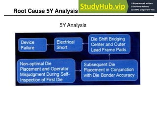
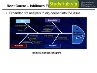


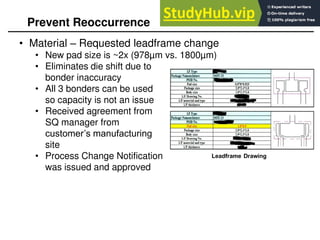


This 8D report summarizes an issue where a die was bonded incorrectly inside a package. The root cause was determined to be the tight tolerance between the die size and leadframe pad size, which could cause misalignment during bonding. Corrective actions included retraining operators, using a bonder with higher accuracy, and requesting a new leadframe design with larger pads to eliminate the issue. The team's work in containing the problem, analyzing the root cause, and implementing preventative solutions was commended.