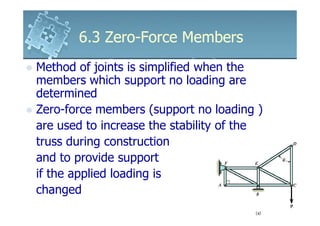
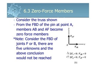
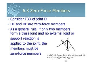
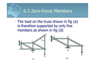
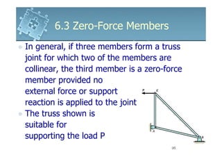
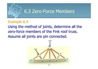
6.3 Zero-Force Members
Method of joints is simplified when the
members which support no loading are
determined
Zero-force members (support no loading )
are used to increase the stability of the
truss during construction
and to provide support
if the applied loading is
changed
6.3 Zero-Force Members
 Consider the truss shown
 From the FBD of the pin at point A,
 members AB and AF become
 zero force members
*Note: Consider the FBD of
 joints F or B, there are
 five unknowns and the
 above conclusion
 would not be reached
6.3 Zero-Force Members
Consider FBD of joint D
DC and DE are zero-force members
As a general rule, if only two members
form a truss joint and no external load or
support reaction is
applied to the joint, the
members must be
zero-force members
6.3 Zero-Force Members

The load on the truss shown in fig (a)
is therefore supported by only five
members as shown in fig (d)
6.3 Zero-Force Members
Consider the truss shown
From the FBD of the pin of the joint D, DA
is a zero-force member
From the FBD of the pin of the joint C, CA
is a zero-force member
6.3 Zero-Force Members
In general, if three members form a truss
joint for which two of the members are
collinear, the third member is a zero-force
member provided no
external force or support
reaction is applied to the joint
The truss shown is
suitable for
supporting the load P
6.3 Zero-Force Members

Example 6.4
Using the method of joints, determine all the
zero-force members of the Fink roof truss.
Assume all joints are pin connected.
6.3 Zero-Force Members
Solution
Joint G
      + ↑ ∑ Fy = 0; FGC = 0
GC is a zero-force member
meaning the 5kN load at C
must be supported by CB, CH, CF and CD

Joint D
      ∑ Fx = 0; FDF = 0
6.3 Zero-Force Members
Solution
Joint F

+ ↑ ∑ Fy = 0; FFC cos θ = 0
θ ≠ 90o , FFC = 0
Joint B
∑ Fx = 0;2kN − FBH = 0
FBH = 2kN (C )
6.3 Zero-Force Members

Solution
FHC satisfy ∑Fy = 0 and therefore HC is not a
zero-force member

6161103 6.3 zero force members

  • 1.
    6.3 Zero-Force Members Methodof joints is simplified when the members which support no loading are determined Zero-force members (support no loading ) are used to increase the stability of the truss during construction and to provide support if the applied loading is changed
  • 2.
    6.3 Zero-Force Members Consider the truss shown From the FBD of the pin at point A, members AB and AF become zero force members *Note: Consider the FBD of joints F or B, there are five unknowns and the above conclusion would not be reached
  • 3.
    6.3 Zero-Force Members ConsiderFBD of joint D DC and DE are zero-force members As a general rule, if only two members form a truss joint and no external load or support reaction is applied to the joint, the members must be zero-force members
  • 4.
    6.3 Zero-Force Members Theload on the truss shown in fig (a) is therefore supported by only five members as shown in fig (d)
  • 5.
    6.3 Zero-Force Members Considerthe truss shown From the FBD of the pin of the joint D, DA is a zero-force member From the FBD of the pin of the joint C, CA is a zero-force member
  • 6.
    6.3 Zero-Force Members Ingeneral, if three members form a truss joint for which two of the members are collinear, the third member is a zero-force member provided no external force or support reaction is applied to the joint The truss shown is suitable for supporting the load P
  • 7.
    6.3 Zero-Force Members Example6.4 Using the method of joints, determine all the zero-force members of the Fink roof truss. Assume all joints are pin connected.
  • 8.
    6.3 Zero-Force Members Solution JointG + ↑ ∑ Fy = 0; FGC = 0 GC is a zero-force member meaning the 5kN load at C must be supported by CB, CH, CF and CD Joint D ∑ Fx = 0; FDF = 0
  • 9.
    6.3 Zero-Force Members Solution JointF + ↑ ∑ Fy = 0; FFC cos θ = 0 θ ≠ 90o , FFC = 0 Joint B ∑ Fx = 0;2kN − FBH = 0 FBH = 2kN (C )
  • 10.
    6.3 Zero-Force Members Solution FHCsatisfy ∑Fy = 0 and therefore HC is not a zero-force member