This document discusses the use of clutter maps in radar signal processing. It describes how clutter maps estimate the mean clutter level on a cell-by-cell basis to accommodate spatially nonstationary clutter distributions. A recursive filter is used to estimate the clutter power from current and previous samples. This provides an exponential smoothing action and reduces the variance of the estimate. The clutter map approach allows targets above the clutter level to be detected over weak ground clutter or precipitation returns.


![= l / X in the hl'l'l)) is atlclcd to 1 - cu of tlic prcvious cstirii;~tcto f'orti~tlic new
cstir~iatc.'I'liis protluccs :in exponential typc of srnoothing action, where tllc cffcct
of cach sati~plcf;~dcsat an exponential rate.
Thc state equation for the first-ordcr rccursivc filter used in the clrlttcr rn:~p
CI:AK is pivcn by ri; = ( 1 - cu)j,-, + ax-),whcrc ?', is the jth output of thc power
cstitnatc, .; is thc jth sample of the interference (clutter and noise) powcr. arid cu is
thc filtcr's gain cocfficicnt. Thc cxpcctcd valuc ol' the power estimatc is gi.en by
E(y,) = P, I I - ( 1 - tu)'l, which ;~ppro;~cIicsE( I ) - l', for I;~rpcvnlr1c501' j Notc
that tlic value ot' cluttcr power (PC)in cach cell is proportional to thc backwattcr
ccxf'ficicnt (cr"), which is assumed to be a rand0111variable in the spatially nonst;~tionnry
cluttcr model dcscribcd in Scction 1.3.4. Thus, thc clutter niap CFAK estiniates the
hackscattcring coefficient (UP) on a cell-to-CCIIb i ~ ~ i ~and hcncc accornniodatcs both
spti;~lly~ ~ I I I O ~ C I I C O U S;lrid ~ i ~ ~ ~ i h o r i w g c n e ~ ~ ~clutter distribitt ions.
Thc variancc of the rccursivc filtcr's estimate of the cluttcr powcr is given by
v , ) = c 1 - ( I - a)"]/[l - ( 1 - a)'],whcrc CT: is the variance o f thu clutter
power rantlorn v;~ri:ildc. For large valucs of j, this :~pproacIicsvat-(!) = rrrr;'/l - n,
which illustrates thc smoothing cffcct of thc filter. Because the variance is rctluccd
by tlic factor ,I' = (2 - cu)/cu, this is cquivalcnt to tlic use of rt' cclls in a cont~cntionnl
cell-averaging CFAR 1441.
One use of thc clutter-map type of CFAR is to provide si~pcrclutter~.i<ihility
in tliusc cluttcr cclls wlicrc the target return signil'icantly cxcccds the cluttcr rcturn.
In [he MTLI proccssor, this allows strong tangential targets (those with sr~lallradial
vcltwitics) to bc dctcctcd ovcr wcak ground clutter or tangentially moving precipitation
rcturns. 'Iliis is particularly advantageous in the hnnation and maintenance ot grounel
tracks that occur in subscqucnt data processing.
A siniplif'ied analysis of the CFAK loss associated with the clutter-map CFAU
proccssor shown in Figurc 1.35 can be made for the situation where a Sw.erling 1
typc fluctuating target is to bc dctcctcd in an unknown powcr Kaylcigll cluttcr
backgrouncl. wlicrc the cluttcr is corriplctcly corrclatcd within a single r;~tl:irscan
1441. 'The prch~hilityo f clctcction for ;I square-law clctcctor ; ~ t l c l ;I lixccl t l i r c.l~olcl
(lqh)is given by Pd, = CXP[--yb/(l + y)], where 7 = PJP, is the nlcan signd-to-
cluttcr poMocrratio. The threshold is cstiniated by the clutter map such that !-,= C$/
PC. wlicrc C is a fixed threshold offset, j, is the clutter power estimate froril the
rccursivc filtcr, and P,. is the cluttcr powcr. Thc V;II~IC for PI,C ; I I ~tllcli be Ivrittcn as
Pll = cxp[-CjJ/IJ,(l + y)],which is a function of the estimated clutter poLvcr (3).
If we average ovcr the cluttcr powcr estimate, this rcsults in l',,, = c.;p[-Cf,/
P,( 1 -1- y3]1'(f) (if, which can bc rccognizcd as thc characteristic fwiction AllS =
C/P,( I + y)] of j cvaluntcd at thc argumcnt of the cxponcntial. The fr~lscalarm
probability can be evaluated froni this relationship evaluated at y = O (i.c.. l'/, =
hl(S = ClI',).
The rccursivc iiltcr of Figure 1.35 provides an estimate of the clutter power
I
foniicci froni the currcnt and previous samples as ?', = aC7-,, ( I = cu).r, _ 'lhc proh:lhility](https://image.slidesharecdn.com/58-64-180623113823/85/58-64-3-320.jpg)
![dcnsity of each .r clutter sample is given by y(s) = exp(-x/P,)/P, so that the
characteristic function of 3 equals M ( s ) = nt,[ I + a(l - a)'pJ]-', which upon
substituhn iu(o the probability of detection relationship becon~esc,,= 11;-,, [ 1 +
I x
1 - t i / I i - 7)) . This reliltio~~sllipC V ~ I ~ U ~ I ~ C ~iit y = 0 res~11tsin I;* = 11,-(,
I
1I -t C U ( I - ( t ) ' ] .
The CFAK loss call be evaluated by first solving the P/, relationship for C and
then substituting (his and an appropriate value of y = ~ J P ,into the PC,,relationship
lo provide ii p;irtic~liuprobihility of tlctection. The known powor ( I ~ - C F A R )valuc
of y, can illen be calculntud from y, = lnPb/lnPd, - 1. The CFAR loss in dB is
then found from id = 10 log(y - y,). This is plotted in Figure 1.36 as a function
of the recursive filter gain (Y for P,, = 0.9 and Ph, =
Figure 1.36 shows that snlall CFAR loss results from using a snlall filtcr gain
ctxl'licient ( t u ) . 'l'his occurs because decreasing a corresponds to using a longcr data
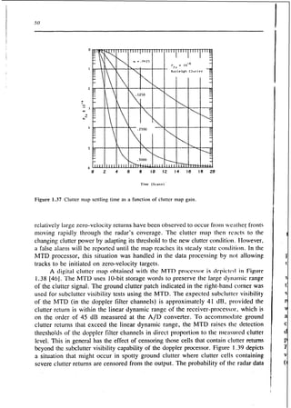
window to csli~natethe clutter power. Conversely, map settling time is reduced as
tr is i n c r c a d as is shown in Figure 1.37 1441. Thus, a compron~isebctwet!n low
Cb'AK loss rlr~tladequate settling time is required. A filtcr gain of cu = .I25 is used
in the hl'I'I), ujhich represents a compromise between these two factors.
ScttII~yt i w I)ecoiilcs important for clutter transients caused by either ch:mging
or moving c.1uttc.r. One example of this situation occurs in the hlTD processor, where
CFAR MAP LOSS
0.00 1.00 2.00 3.00 4.00 5.00 6.00 7.00 8.00
WEIGHT VALUE (8th'sl](https://image.slidesharecdn.com/58-64-180623113823/85/58-64-4-320.jpg)