This PowerPoint presentation is for Grade 10 students. I have included all the topics in this presentation. Here you can know about Light, Types of lenses, Some terms related to lens, Prism, Ray diagrams, Numerical problems related to this chapter, Laws of reflection, refraction, diseases related to eyes. I have briefly described as notes, some examples and illustrations, proper diagrams and so on.
This PowerPoint presentation is for Grade 10 students. I have included all the topics in this presentation. Here you can know about Light, Types of lenses, Some terms related to lens, Prism, Ray diagrams, Numerical problems related to this chapter, Laws of reflection, refraction, diseases related to eyes. I have briefly described as notes, some examples and illustrations, proper diagrams and so on.
Untuk selengkapnya silahkan di
hendroagungs.blogspot.com adalah sebuah blog kumpulan materi kuliah dalam bentuk powerpoint maupun pdf dan word, bila ada kritik atau saran silahkan kontak bisnishendroagung@gmail.com
ini dia.. Mr.John mau presentasikan dan berbagi materi bagi adik adik atau teman teman yang butuh referensi dalam menghadapi dan latihan Olimpiade Fisika
Honest Reviews of Tim Han LMA Course Program.pptxtimhan337
Personal development courses are widely available today, with each one promising life-changing outcomes. Tim Han’s Life Mastery Achievers (LMA) Course has drawn a lot of interest. In addition to offering my frank assessment of Success Insider’s LMA Course, this piece examines the course’s effects via a variety of Tim Han LMA course reviews and Success Insider comments.
Synthetic Fiber Construction in lab .pptxPavel ( NSTU)
Synthetic fiber production is a fascinating and complex field that blends chemistry, engineering, and environmental science. By understanding these aspects, students can gain a comprehensive view of synthetic fiber production, its impact on society and the environment, and the potential for future innovations. Synthetic fibers play a crucial role in modern society, impacting various aspects of daily life, industry, and the environment. ynthetic fibers are integral to modern life, offering a range of benefits from cost-effectiveness and versatility to innovative applications and performance characteristics. While they pose environmental challenges, ongoing research and development aim to create more sustainable and eco-friendly alternatives. Understanding the importance of synthetic fibers helps in appreciating their role in the economy, industry, and daily life, while also emphasizing the need for sustainable practices and innovation.
Instructions for Submissions thorugh G- Classroom.pptxJheel Barad
This presentation provides a briefing on how to upload submissions and documents in Google Classroom. It was prepared as part of an orientation for new Sainik School in-service teacher trainees. As a training officer, my goal is to ensure that you are comfortable and proficient with this essential tool for managing assignments and fostering student engagement.
Macroeconomics- Movie Location
This will be used as part of your Personal Professional Portfolio once graded.
Objective:
Prepare a presentation or a paper using research, basic comparative analysis, data organization and application of economic information. You will make an informed assessment of an economic climate outside of the United States to accomplish an entertainment industry objective.
The French Revolution, which began in 1789, was a period of radical social and political upheaval in France. It marked the decline of absolute monarchies, the rise of secular and democratic republics, and the eventual rise of Napoleon Bonaparte. This revolutionary period is crucial in understanding the transition from feudalism to modernity in Europe.
For more information, visit-www.vavaclasses.com
2024.06.01 Introducing a competency framework for languag learning materials ...Sandy Millin
http://sandymillin.wordpress.com/iateflwebinar2024
Published classroom materials form the basis of syllabuses, drive teacher professional development, and have a potentially huge influence on learners, teachers and education systems. All teachers also create their own materials, whether a few sentences on a blackboard, a highly-structured fully-realised online course, or anything in between. Despite this, the knowledge and skills needed to create effective language learning materials are rarely part of teacher training, and are mostly learnt by trial and error.
Knowledge and skills frameworks, generally called competency frameworks, for ELT teachers, trainers and managers have existed for a few years now. However, until I created one for my MA dissertation, there wasn’t one drawing together what we need to know and do to be able to effectively produce language learning materials.
This webinar will introduce you to my framework, highlighting the key competencies I identified from my research. It will also show how anybody involved in language teaching (any language, not just English!), teacher training, managing schools or developing language learning materials can benefit from using the framework.
Francesca Gottschalk - How can education support child empowerment.pptxEduSkills OECD
Francesca Gottschalk from the OECD’s Centre for Educational Research and Innovation presents at the Ask an Expert Webinar: How can education support child empowerment?
Operation “Blue Star” is the only event in the history of Independent India where the state went into war with its own people. Even after about 40 years it is not clear if it was culmination of states anger over people of the region, a political game of power or start of dictatorial chapter in the democratic setup.
The people of Punjab felt alienated from main stream due to denial of their just demands during a long democratic struggle since independence. As it happen all over the word, it led to militant struggle with great loss of lives of military, police and civilian personnel. Killing of Indira Gandhi and massacre of innocent Sikhs in Delhi and other India cities was also associated with this movement.
Unit 8 - Information and Communication Technology (Paper I).pdfThiyagu K
This slides describes the basic concepts of ICT, basics of Email, Emerging Technology and Digital Initiatives in Education. This presentations aligns with the UGC Paper I syllabus.
June 3, 2024 Anti-Semitism Letter Sent to MIT President Kornbluth and MIT Cor...Levi Shapiro
Letter from the Congress of the United States regarding Anti-Semitism sent June 3rd to MIT President Sally Kornbluth, MIT Corp Chair, Mark Gorenberg
Dear Dr. Kornbluth and Mr. Gorenberg,
The US House of Representatives is deeply concerned by ongoing and pervasive acts of antisemitic
harassment and intimidation at the Massachusetts Institute of Technology (MIT). Failing to act decisively to ensure a safe learning environment for all students would be a grave dereliction of your responsibilities as President of MIT and Chair of the MIT Corporation.
This Congress will not stand idly by and allow an environment hostile to Jewish students to persist. The House believes that your institution is in violation of Title VI of the Civil Rights Act, and the inability or
unwillingness to rectify this violation through action requires accountability.
Postsecondary education is a unique opportunity for students to learn and have their ideas and beliefs challenged. However, universities receiving hundreds of millions of federal funds annually have denied
students that opportunity and have been hijacked to become venues for the promotion of terrorism, antisemitic harassment and intimidation, unlawful encampments, and in some cases, assaults and riots.
The House of Representatives will not countenance the use of federal funds to indoctrinate students into hateful, antisemitic, anti-American supporters of terrorism. Investigations into campus antisemitism by the Committee on Education and the Workforce and the Committee on Ways and Means have been expanded into a Congress-wide probe across all relevant jurisdictions to address this national crisis. The undersigned Committees will conduct oversight into the use of federal funds at MIT and its learning environment under authorities granted to each Committee.
• The Committee on Education and the Workforce has been investigating your institution since December 7, 2023. The Committee has broad jurisdiction over postsecondary education, including its compliance with Title VI of the Civil Rights Act, campus safety concerns over disruptions to the learning environment, and the awarding of federal student aid under the Higher Education Act.
• The Committee on Oversight and Accountability is investigating the sources of funding and other support flowing to groups espousing pro-Hamas propaganda and engaged in antisemitic harassment and intimidation of students. The Committee on Oversight and Accountability is the principal oversight committee of the US House of Representatives and has broad authority to investigate “any matter” at “any time” under House Rule X.
• The Committee on Ways and Means has been investigating several universities since November 15, 2023, when the Committee held a hearing entitled From Ivory Towers to Dark Corners: Investigating the Nexus Between Antisemitism, Tax-Exempt Universities, and Terror Financing. The Committee followed the hearing with letters to those institutions on January 10, 202
Read| The latest issue of The Challenger is here! We are thrilled to announce that our school paper has qualified for the NATIONAL SCHOOLS PRESS CONFERENCE (NSPC) 2024. Thank you for your unwavering support and trust. Dive into the stories that made us stand out!
1. Handout : Optik Geometri (Nur Aji Wibowo, M.Si)
1
GEOMETRIC OPTICS
Images can be formed either by reflection or by refraction and that mirrors and lenses work because
of reflection and refraction. We continue to use the ray approximation and to assume that light travels
in straight lines. Both of these steps lead to valid predictions in the field called geometric optics.
Images
Real image:
is formed when light rays pass through and diverge from the image point
can be displayed on a screen (as at a movie)
Virtual image:
is formed when the light rays do not pass through the image point but appear to diverge from
that point
cannot be displayed on a screen
A. IMAGES FORMED BY REFLECTION
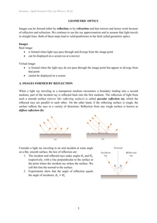
When a light ray traveling in a transparent medium encounters a boundary leading into a second
medium, part of the incident ray is reflected back into the first medium. The reflection of light from
such a smooth surface (mirror like reflecting surface) is called specular reflection (a), which the
reflected rays are parallel to each other. On the other hand, if the reflecting surface is rough, the
surface reflects the rays in a variety of directions. Reflection from any rough surface is known as
diffuse reflection (b).
Consider a light ray traveling in air and incident at some angle
on a flat, smooth surface, the law of reflection are:
1. The incident and reflected rays make angles and ,
respectively, with a line perpendicular to the surface at
the point where the incident ray strikes the surface. We
call this line the normal to the surface.
2. Experiments show that the angle of reflection equals
the angle of incidence, .
2. Handout : Optik Geometri (Nur Aji Wibowo, M.Si)
2
IMAGES FORMED BY FLAT MIRRORS
Image properties of flat mirror :
• PQ = QP’
• equal
• Virtual
• Upright
• Face off
Multiple Images Formed by Two Mirrors
IMAGES FORMED BY SPHERICAL MIRRORS
Concave Mirrors
A mirror, in which light is reflected from the inner, concave surface, is called a concave
mirror
Focuses incoming parallel rays to a point
Has a radius of curvature R
Its center of curvature is point C
Point V is the center of the spherical section, and a line through C and V is called the
principal axis of the mirror
In this section only rays that diverge from the object and make a small angle with the
principal axis. Such rays are called paraxial rays
3. Handout : Optik Geometri (Nur Aji Wibowo, M.Si)
3
Rays that are far from the principal axis, converge to other points on the principal axis, producing a
blurred image. This effect, which is called spherical aberration, is present to some extent for any
spherical mirror.
Derivation of Mirror Equation
the magnification is defined as
the relation of p , q and R can be derived from
Small angle
4. Handout : Optik Geometri (Nur Aji Wibowo, M.Si)
4
from that equation we find the Mirror Equation in R form
( )
( ) ( )
Focuses incoming parallel rays to a point
Parallel rays ≈ if p is so much greater than R that p can be
said to approach infinity ( ),
We call the image point in this special case the focal point F
and the image distance the focal length f
Light rays from a distant object ( ) reflect from a concave mirror through the focal point F
So, the mirror equation can be written as
IMAGES FORMED BY SPHERICAL MIRRORS
Convex Mirror
Called a diverging mirror because the rays from any point on an object diverge after reflection
as though they were coming from some point behind the mirror
We can use Equations of concave mirror for either concave or convex mirrors if we add the
following procedure:
5. Handout : Optik Geometri (Nur Aji Wibowo, M.Si)
5
Sign Conventions for Mirrors
Properties (+) positive (-) negative
p
(object)
front (real) back (virtual)
q
(image)
front (real) back (virtual)
f , R
concave
(center of curvature is in front of
mirror)
convex
(center of curvature is in back of
mirror)
M Upright inverted
Ray Diagrams for Mirrors
• Ray 1 is drawn from the top of the object parallel to the principal axis and is reflected through
the focal point f
• Ray 2 is drawn from the top of the object through the focal point and is reflected parallel to
the principal axis.
a. Convex mirror b. Concave mirror
a. Convex mirror b. Concave mirror
6. Handout : Optik Geometri (Nur Aji Wibowo, M.Si)
6
• Ray 3 is drawn from the top of the object through the center of curvature C and is reflected
back on itself.
Image formation of the mirrors
Example 1
When the object is located so that the center of curvature lies between the object and a concave mirror
surface, the image is real, inverted, and reduced in size.
Example 2
When the object is located between the focal point and a concave mirror surface, the image is virtual,
upright, and enlarged.
a. Convex mirror b. Concave mirror
7. Handout : Optik Geometri (Nur Aji Wibowo, M.Si)
7
Example 3
When the object is in front of a convex mirror, the image is virtual, upright, and reduced in size.
B. IMAGES FORMED BY REFRACTION
An Image Formed by Spherical Refracting Surfaces
Geometry used to derive the equation of refraction at a spherical surface
When incident and refraction angle are assumed to be small, we can use the small-angle
approximation and (angles in radians) and Snell’s law can be said that
8. Handout : Optik Geometri (Nur Aji Wibowo, M.Si)
8
Applying this rule to triangles OPC and PIC in Figure above gives
If we combine all three expressions and eliminate and , we find that
⁄
Multiply the first equation with , and the second equation with
by eliminate the , can be simplified as
the equation becomes
( )
Rays making small angles with the principal axis diverge from a point object at O and are refracted
through the image point I. In the small-angle approximation, , so we can write the
approximate relationships from these triangles as follows:
by substituting this equation to the equation before,
( )
and we get the Spherical Refracting Surfaces equation
where
= refraction index of medium at which the object placed on
= refraction index of medium at which the viewer stayed on
9. Handout : Optik Geometri (Nur Aji Wibowo, M.Si)
9
= distances of object
= distances of image
For a fixed object at distance p, the image at distance q is independent of the angle that the ray makes
with the axis. This result tells us that all paraxial rays focus at the same point I.
Sign Conventions for Refracting Surfaces
Properties (+) positive (-) negative
p
(object)
front of surface (real object) back of surface (virtual)
q
(image)
back of surface (real image) front of surface (virtual image)
R
center of curvature is in back of
convex surface
center of curvature is in front of
concave surface
Flat Refracting Surfaces
If a refracting surface is flat, then and the Spherical Refracting Surfaces equation can be
reduces to
or we can express as
From this expression we see that the sign of q is opposite that of p.
For , the image formed by a flat refracting surface
is virtual and on the same side of the surface as the object
(a virtual image is formed between the object and the
surface). The Figures below show the image formation on
flat refracting surfaces for .
For , the rays in the back side diverge from each
other at lesser angles than those Figures. As a result, the
virtual image is formed to the left of the object. (All rays
are assumed to be paraxial)
10. Handout : Optik Geometri (Nur Aji Wibowo, M.Si)
10
Thin Lenses
To investigate the image formed by thin lenses, we shall note that the image formed by one
refracting surface serves as the object for the second surface. We shall analyze a thick lens first
and then let the thickness of the lens be approximately zero.
Assuming that (the lens is surrounded by air), (the object is placed close to surface 1)
and taking , let start the investigation with the virtual image formed by surface 1. Using the
Spherical Refracting Surfaces equation, the image I1 formed by surface 1 satisfies the equation
( )
where is a negative number because it represents a virtual image formed on the front side of
surface 1.
The investigation will continued by applying the Spherical Refracting Surfaces equation to surface 2.
Taking and , the image I2 formed by surface 2 satisfies the equation
( )
From the Figure above,
(Note: shows virtual image from surface 1 and is thickness of lenses). For thin lenses, we can
neglect the thickness, , and the equation becomes
By adding this equation with eq (a), the final equation of thin lenses
( ) ( )
11. Handout : Optik Geometri (Nur Aji Wibowo, M.Si)
11
We can express that equation in term of , which called lens makers equation
( ) ( )
Thin lens has a similar equation with mirror equation, which called thin lens equation which relate
the image distance and object distance for a thin lens
( ) ( )
As with mirrors, the lateral magnification of the lens is defined as the ratio of the image height h’ to
the object height h.
The Figure below show the Simplified geometry for a thin lens
Because light can travel in either direction through a lens, each lens has two focal points, one for light
rays passing through in one direction and one for rays passing through in the other direction. Focal
point F1 is sometimes called the object focal point, and F2 is called the image focal point.
(a). Convex lens (b). Concave lens
12. Handout : Optik Geometri (Nur Aji Wibowo, M.Si)
12
Sign Conventions for thin lenses
Properties (+) positive (-) negative
p
(object)
front of lens (real object) back of lens (virtual object)
q
(image)
back of lens (real image) front of lens (virtual image)
R center of curvature is in back of lens center of curvature is in front of lens
f converging diverging
M
Upright
on the same side of the lens as the object
inverted
Various Lens Shapes
(a) Biconvex, convex–concave, and plano–
convex. These are all converging lenses; they
have a positive focal length and are thickest at
the middle.
(b) Biconcave, convex–concave, and plano–
concave. These are all diverging lenses; they
have a negative focal length and are thickest at
the edges.
Magnification of Images
As with mirrors, the lateral magnification of the lens is defined as the ratio of the image height h to the
object height h’:
Ray Diagrams for Thin Lenses
Converging lens
for p > f
13. Handout : Optik Geometri (Nur Aji Wibowo, M.Si)
13
for p < f
• Ray 1 is drawn parallel to the principal axis. After being refracted by the lens, this ray passes
through the focal point on the back side of the lens.
• Ray 2 is drawn through the center of the lens and continues in a straight line.
• Ray 3 is drawn through that focal point on the front side of the lens (or as if coming from the
focal point if p < f ) and emerges from the lens parallel to the principal axis.
Diverging lens
Ray 1 is drawn parallel to the principal axis. After being refracted by the lens, this ray
emerges such that it appears to have passed through the focal point on the front side of the
lens (This apparent direction is indicated by the dashed line in Figure above).
Ray 2 is drawn through the center of the lens and continues in a straight line.
Ray 3 is drawn toward the focal point on the back side of the lens and emerges from the lens
parallel to the optic axis.
Combination of Thin Lenses
If two thin lenses are used to form an image, the two thin lenses are
touching, the system can be treated in the following manner. First,
the image formed by the first lens is located as if the second lens
were not present. Then a ray diagram is drawn for the second lens,
with the image formed by the first lens now serving as the object for
the second lens. The second image formed is the final image of the
system. One configuration is particularly straightforward; that is, if
the image formed by the first lens lies on the back side of the second lens, then that image is treated as
a virtual object for the second lens (that is, p is negative). The same procedure can be extended to a
system of three or more lenses. The overall magnification of a system of thin lenses equals the product
of the magnifications of the separate lenses.
If p1 is the object distance for the combination, application of the thin-lens equation to the first lens
gives
14. Handout : Optik Geometri (Nur Aji Wibowo, M.Si)
14
where q1 is the image distance for the first lens. Treating this image as the object for the second lens,
because the two thin lenses are touching, we see that the object distance for the second lens, p2 = - q1
(negative because the object is virtual). Therefore, for the second lens,
where q is the final image distance from the second lens. Adding these equations eliminates q1 and
gives
Because the two thin lenses are touching, p1 is also the distance of the object from the both lens (p)
and q2 is also the distance of the final image from the both lens (q). The equation can be express as
where fR is a resultant focal length. Therefore, two thin lenses in contact with each other are
equivalent to a single thin lens having a resultant focal length given by Equation above.
LENS ABERRATIONS
One problem with lenses is imperfect images. The theory of mirrors and lenses that we have been
using assumes that rays make small angles with the principal axis and that the lenses are thin. In this
simple model, all rays leaving a point source focus at a single point, producing a sharp image. Clearly,
this is not always true. When the approximations used in this theory do not hold, imperfect images are
formed. The departures of actual (imperfect) images from the ideal predicted by theory are called
aberrations.
Spherical Aberrations
Spherical aberrations occur because the focal points of
rays far from the principal axis of a spherical lens (or
mirror) are different from the focal points of rays of the
same wavelength passing near the axis.
15. Handout : Optik Geometri (Nur Aji Wibowo, M.Si)
15
Chromatic Aberrations
The fact that different wavelengths of light refracted by a
lens focus at different points gives rise to chromatic
aberrations.
References:
Halliday, Resnick - Fundamentals of Physics. (Ch. 36. Geometric Optic. pg.1139 – 1171)
Serway, R - College Physics 7th Ed. (Ch. 23. Mirrors and Lenses, pg. 754 – 785)
16. Handout : Optik Geometri (Nur Aji Wibowo, M.Si)
16
Optical Instruments
The Simple Magnifier
Principle
Consists of a single converging lens
Increases the apparent size of an object
Angular magnification M as the ratio of the angle subtended by an object with a lens in use to the
angle subtended by the object placed at the near point with no lens in use.
When the image is at the near point of the eye - that is, when q = - Sn, The angular magnification is a
maximum. So, the object distance corresponding to this image distance can be calculated.
Sn
17. Handout : Optik Geometri (Nur Aji Wibowo, M.Si)
17
for small angle approximations,
........................................................
References:
Halliday, Resnick - Fundamentals of Physics. (Ch. 36. Geometric Optic. pg.1139 – 1171)
Serway, R - College Physics 7th Ed. (Ch. 23. Mirrors and Lenses, pg. 754 – 785)