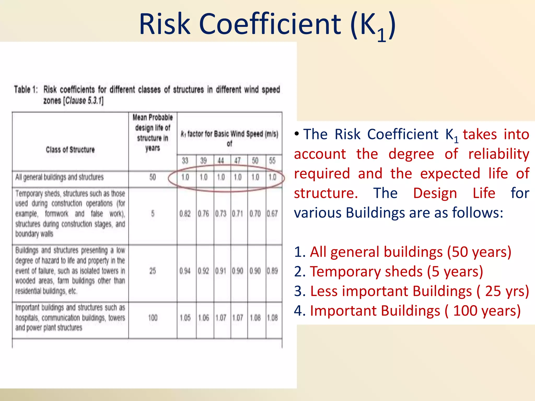
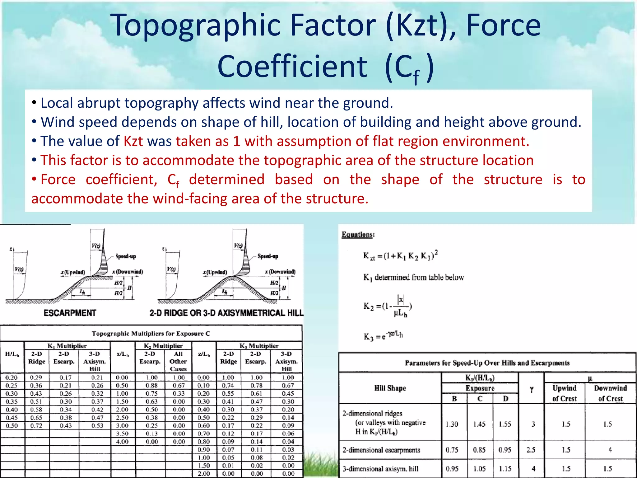
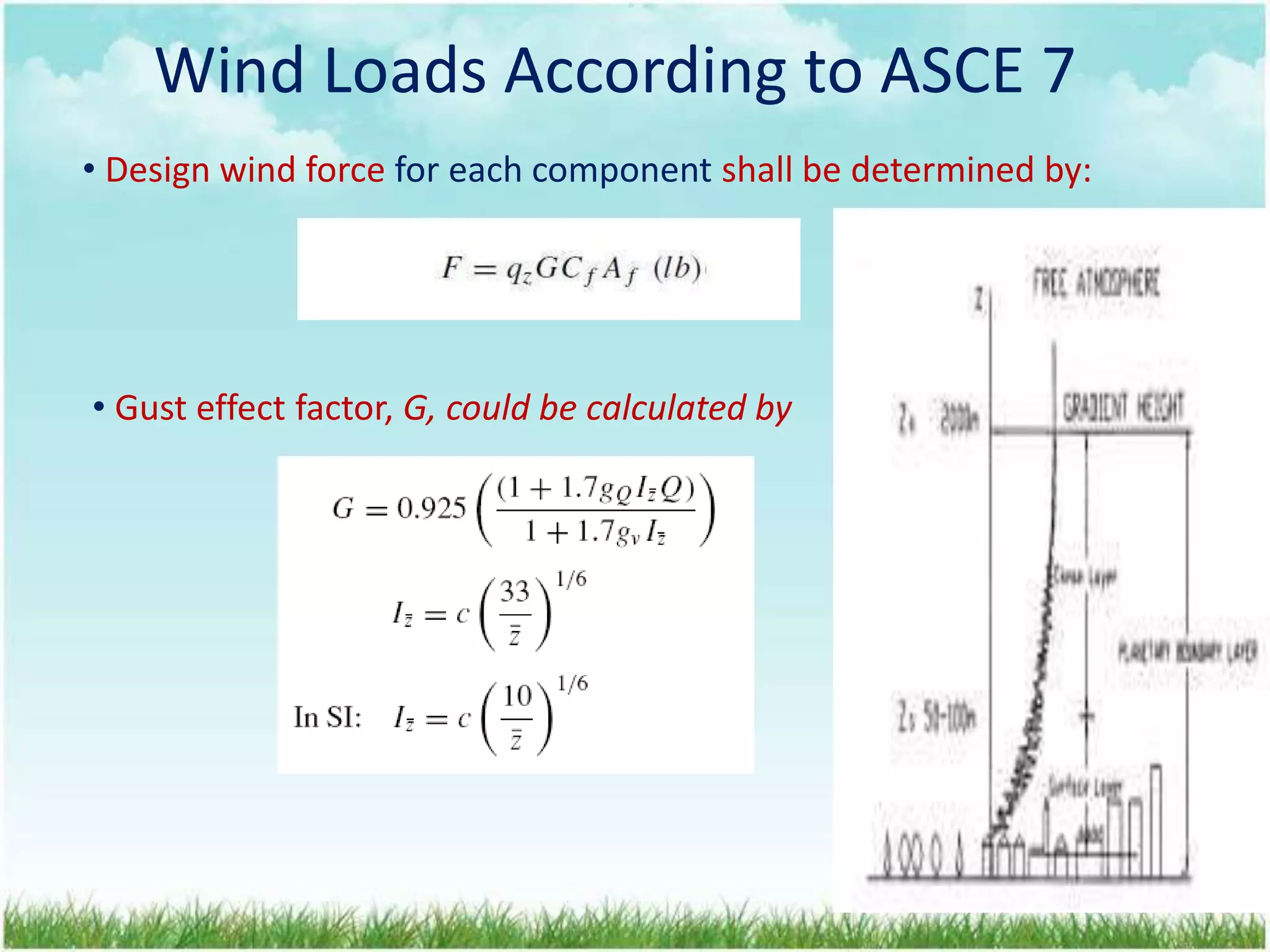
The document discusses wind load analysis on buildings and structures according to Indian and American codes. It provides objectives of analyzing wind loads and calculating design wind speed, pressure, and forces on structures. Key steps include obtaining basic wind speed, calculating risk coefficients, terrain and structure size factors, and determining design wind pressure and forces on buildings. The document compares the Indian Standard Code IS 875 with the American Society of Civil Engineers code ASCE-7, noting some differences in factors and equations used between the two codes.
Wind load calculations were performed for a 10-story building with a height of 30 meters located in Vadodara, India. The design wind speed was calculated at different heights using the basic wind speed, probability, terrain, and topography factors according to Indian code IS 875. The design wind pressure was then determined and used to calculate the wind load in kN/m applying the effective frontal area and force coefficient. Finally, the wind load was calculated at each floor level.
The document discusses the analysis and design of hoarding structures under wind loads according to code provisions. It provides methods to calculate the design wind speed at any height based on probability factor, terrain conditions, topography, and importance of structure. It also describes how to determine wind pressure and design forces on structures. An example is given to calculate wind loads on a 10m x 5m hoarding located at the roof of a 24m building near Delhi and design the hoarding structure.
Parametric Study for Wind Design of Vertical Pressure Vessel as per Indian St...IJMER
International Journal of Modern Engineering Research (IJMER) is Peer reviewed, online Journal. It serves as an international archival forum of scholarly research related to engineering and science education.
International Journal of Modern Engineering Research (IJMER) covers all the fields of engineering and science: Electrical Engineering, Mechanical Engineering, Civil Engineering, Chemical Engineering, Computer Engineering, Agricultural Engineering, Aerospace Engineering, Thermodynamics, Structural Engineering, Control Engineering, Robotics, Mechatronics, Fluid Mechanics, Nanotechnology, Simulators, Web-based Learning, Remote Laboratories, Engineering Design Methods, Education Research, Students' Satisfaction and Motivation, Global Projects, and Assessment…. And many more.
The document presents information on deriving wind actions on structures according to Eurocode 1: 1991-1-4 and the UK National Annex. It discusses the steps to assess wind load on buildings, including determining the basic wind velocity, peak wind pressure, external and internal pressure coefficients, and the structural factor. It also provides examples of calculating wind loads on a warehouse building and high-rise building.
CHAPTER 3 (part 1) Wind Load and procedure.pptxMamushLeta
The document discusses wind loads and earthquake loads on structures according to Eurocode standards. It provides classifications of loads and an overview of wind loads, defining wind as moving air with mass and kinetic energy. Wind speeds are typically measured 10m above the ground. It describes modelling wind actions through peak velocity pressure, force coefficients, and a structural factor. Terrain categories, roughness factors, and orography factors are defined for calculating mean wind speeds at different heights. Pressure coefficients are used to determine wind pressures on external and internal surfaces. Structural response is assessed through wind forces calculated from surface pressures and force coefficients.
This document discusses wind load design for tall buildings. It states that wind load is the most important factor for buildings over 10 storeys tall. Wind loads are estimated using static and dynamic approaches. The document also provides guidance on instrumentation for monitoring wind data on tall structures, types of wind effects, dynamic wind analysis procedures, code provisions for wind speed and pressure calculations, and examples calculating wind loads using force coefficient and gust factor methods.
This document discusses calculating wind loads on structures according to the ASCE 7 standard. Wind loads are dynamic loads that depend on factors like wind speed, structure height and shape, surface roughness, and location. The calculation involves determining the basic wind speed, then applying adjustment factors for directionality, importance, height, topography, force coefficients, gust effects, and others to calculate the total design wind force and moments on each structural component.
This document discusses the calculation of wind loads for structural design. It provides background on wind loads and defines key terms. It outlines wind speed areas in Tanzania and the design procedure, which involves determining the site wind speed, characteristic wind pressure, external and internal pressures on the structure, and the net pressure. Examples are provided to demonstrate calculating wind loads. Load factors of safety and load combinations are also defined.
Performance of High-Rise Steel Building With and Without BracingsIJERA Editor
A comparative study on performance of high-rise steel building with and without bracings, carried
out on a residential building by considering the gravity loads and lateral loads in the form of Earth quake loads
and Wind loads incorporating the Bracings to reduce lateral loads on structural elements. In this study, a 20
storey steel frame structure has been selected to be idealized as multi storey steel building model. The model is
analyzed by using STAAD.Pro 2008 structural analysis software with the consideration of wind and earthquake
loads. At the same time the influence of X-bracing pattern has been investigated.The building proposed in
designed by Limit State Method according to steel code IS: 800-2007, the Wind load analysis according to IS:
875-(part-3)1987 and seismic/Earth quake loads according to IS: 1893 (Part-1)-2002. In this study the node
displacements of buildings having with and without bracings of wind and earthquake effect of Zone II and
Zone V, and the axial force of the members of the buildings having with and without bracings of wind and
earthquake effect of Zone II and Zone V.
This document provides information about a group project analyzing the effects of wind on different types of roof structures. It lists the group members and introduces the topics to be analyzed, including flat roofs, pitched roofs, and hipped roofs. The methodology will use software to independently analyze different roof types and compare the results. Relevant codes and materials will be applied. The study area is Adama, Ethiopia, located at an average altitude of 1712 meters above sea level.
Wind load analysis involves calculating wind pressures on buildings based on factors like basic wind speed, risk coefficient, terrain category, and structure height. Wind loads are distributed to joints in the structural model. STAAD Pro defines wind loads by specifying intensities at different heights, then applies the loads. Key load combinations include 1.5(D+W) and 1.2(D+L+W) for the wind load limit state.
This document discusses wind loads on structures. It describes how high velocity winds create low pressure areas that exert lifting and pulling forces on buildings. Wind load is classified as static or dynamic, with static wind causing elastic bending and twisting, while dynamic wind from gusts induces oscillations. Wind load analysis is used for structures over 10-30 meters tall. Design wind speed is calculated per IS code 875 using factors for probability, terrain height/structure size, and topography. The key effects of wind load are uplift, shear, and lateral loads.
This document discusses design wind load and terminology according to Indian standard code IS 875 (III). It defines key terms like angle of attack, breadth, depth, developed height, effective frontal area, element surface area, force coefficient, gust, peak gust, fetch length, gradient height, pressure coefficient, suction, velocity profile, and topography. It also covers how to calculate design wind speed based on risk coefficient and terrain/height/structure size factor, and how to determine design wind pressure and force coefficients to calculate total wind load on a structure.
Effect of wind Load On High Rise BuildingVikas Patre
Wind load is an important design consideration for high-rise buildings due to the increasing wind forces experienced at greater heights. This document discusses wind load calculation and analysis for a 20.5m high building according to Indian code IS 875-Part 3. Static analysis of the building model in SAP2000 showed that wind load causes higher bending moments and shear forces compared to analysis without wind load. The wind pressure varies with height and building designers must account for this gradient in load to safely structure high-rise buildings.
The document provides information about calculating wind load on an industrial building located in Chennai, India. It gives the dimensions of the building as 15m x 30m with a frame span of 15m and column height of 6m. It outlines the process to calculate the design wind speed using factors for risk, terrain, and topography. It then calculates the design wind pressure and uses this to calculate the wind load on the walls and roof of the building, finding values of 28.8 kN for the walls and 38.7 kN for the roof.
Soil Structure Interaction Effect for A Building Resting on Sloping Ground In...IRJET Journal
1) The document presents the results of a seismic analysis of an 8-story stepped building resting on sloping ground with slopes of 16, 20, and 24 degrees.
2) Soil structure interaction was considered for hard, medium, and soft soils. Key response parameters like base shear, fundamental time period, maximum story displacement, and axial force were compared for buildings with fixed and flexible bases.
3) The analysis found that soil structure interaction reduced base shear but increased fundamental time period, story displacement, and axial force. Response values were most affected for soft soils compared to medium and hard soils.
Effects of shape on the wind instigate response of high rise buildingseSAT Journals
Abstract A large number of structures that are being constructed at present tend to be wind-sensitive because of their slenderness, shapes, size, lightness and flexibility. With the ever increase in the vertical growth of urban cities, high rise buildings are being constructed in large numbers. In this study, analytical investigation of different shapes of buildings are taken as an example and various analytical approaches are performed on the building. These plans are modeled and wind loads are found out according to I.S 875(part 3)-1987 by taking gust factor and without taking gust factor. These models are compared in different aspects such as storey drift, storey displacement, storey shear, etc. for different shapes of buildings by using finite element software package ETAB’s 13.1.1v. Among these results, which shape of building provide sound wind loading to the structure as well as the structural efficiency would be selected. Key Words: Storey displacement, Storey drift, Storey shear, Gust, Wind load
Study on Effect of Wind Load and Earthquake Load on Multi-storey RC Framed Bu...IJSRD
This document summarizes a study on the effects of wind and earthquake loads on multi-storey reinforced concrete framed buildings. Six different building models with varying use of shear walls were analyzed using structural analysis software to determine parameters like base shear, displacement, story drift, story forces. Results showed that models incorporating shear walls experienced reduced displacement, drift and forces compared to models without shear walls. As lateral loads like wind and earthquakes become more influential in tall building design, shear walls can effectively resist these loads and provide a more stable and economic structure.
The document summarizes the design of an earthquake resistant 8-story building in Lucknow, India. It describes the structural scheme as a 3D space frame modeled in STAAD and analyzed using response spectrum analysis. Load cases considered include dead load, live load, wind load, and earthquake load calculated according to Indian standards. Reinforced concrete design of beams and columns is carried out per IS codes, with M35 concrete grade and Fe415 reinforcement. Load combinations are analyzed to determine the worst case for structural member design.
IRJET- Codal Comparison of IS-875 (Part 3) 1987 and IS-875 (Part 3) 2015 for ...IRJET Journal
The document compares wind load analysis using the Indian Standard codes IS-875 (Part 3) 1987 and IS-875 (Part 3) 2015 for a G+17 high-rise building in Delhi, India. Wind loads are calculated using ETABS software based on parameters from each code. Results like gust factor, lateral force, intensity, storey drift, and displacement are plotted in graphs comparing the two codes. The new 2015 code incorporates revisions like explicitly defined terrain categories and aerodynamic roughness heights, removal of structure type classifications, additional importance factor for cyclonic areas, and empirical expressions for wind speed and turbulence intensity variations with height. Analysis shows gust factors are higher in the new code, increasing lateral loads and requiring stronger building design
IRJET- Wind Load Analysis for Different Configuration of StructuresIRJET Journal
This document summarizes a study that analyzed wind load on two multi-story building models - a square plan model and rectangular plan model - using Staad-Pro software. Wind loads were calculated according to Indian standard IS 875 Part 3 and applied in different directions. The study found that under wind loads, the rectangular plan building model experienced higher maximum displacements, especially at the building edges, compared to the square plan building model. The document concludes that rectangular building frames experience greater displacements than square frames when wind load is applied along the length of the building.
This document analyzes and discusses the connection designs of precast load bearing walls in multi-story buildings subjected to seismic and wind loads. It presents the modeling and analysis of a G+11 story precast concrete shear wall structure using ETABS software. The effects of various seismic zones and wind speeds on structural responses like out-of-plane moments, axial forces, shear forces, base shear, story drift, and tensile forces in the shear walls are extracted and plotted. Maximum values of these responses at different story levels are compared for different seismic zones and wind speeds. Finally, the effect of seismic zone and wind zone on the structural behavior is summarized in tabular form.
Analysis of Wind Load Effects on R.C Structure Resting on Flat and Sloping Gr...IRJET Journal
This document analyzes the effects of wind loads on reinforced concrete structures resting on flat and sloping ground using ETABS software. 36 models are created to analyze structures of varying heights (G+5, G+10, G+15) in different wind zones (3, 4, 5) on slopes of 0, 10, 20, and 30 degrees. Results for story displacement, drift, mode period are checked and compared to code requirements and manual calculations. The analysis aims to evaluate wind load distribution, compare effects of flat and sloping ground, study structural behavior, assess stability, optimize design, and validate design codes to improve structural design and resistance to wind loads.
Study of Comparison Between Static and Dynamic Analysis Subjected to Wind and...IRJET Journal
This document discusses a study comparing static and dynamic analysis of wind and earthquake loads on high-rise buildings. It provides background on wind loads, describes the objectives of investigating parameters like fundamental time period and displacements under dynamic loads. It also outlines the methodology, including design wind load calculation according to Indian codes, modeling a 150m building as a case study, and analyzing it both statically and dynamically under along-wind and across-wind loads.
Comparisons of Shallow Foundations in Different Soil ConditionIJMERJOURNAL
ABSTRACT: Soil is considered by the engineer as a complex material produced by weathering of the solid rock. Footings are structural elements that transmit column or wall loads to the underlying soil below the structure. Footings are designed to transmit these loads to the soil without exceeding its safe bearing capacity. Each building demands the need to solve a problem of foundation on different types of soil. The main aim of this project is to design the appropriate foundation as per size and shape on cohesive, non-cohesive and rocky soil. In this paper different foundation are studied for a middle side and corner column of a building with different bearing capacities. Based on the study and judicial judgment the type of foundation is decided as per depth, quantity of steel and quantity of concrete and try to find which shape of the foundation is more stable, economical and ways to reduce the ease of construction of the building
Job Finding Apps Everything You Need to Know in 2024SnapJob
SnapJob is revolutionizing the way people connect with work opportunities and find talented professionals for their projects. Find your dream job with ease using the best job finding apps. Discover top-rated apps that connect you with employers, provide personalized job recommendations, and streamline the application process. Explore features, ratings, and reviews to find the app that suits your needs and helps you land your next opportunity.
Jill Pizzola's Tenure as Senior Talent Acquisition Partner at THOMSON REUTERS...dsnow9802
Jill Pizzola's tenure as Senior Talent Acquisition Partner at THOMSON REUTERS in Marlton, New Jersey, from 2018 to 2023, was marked by innovation and excellence.
5 Common Mistakes to Avoid During the Job Application Process.pdfAlliance Jobs
The journey toward landing your dream job can be both exhilarating and nerve-wracking. As you navigate through the intricate web of job applications, interviews, and follow-ups, it’s crucial to steer clear of common pitfalls that could hinder your chances. Let’s delve into some of the most frequent mistakes applicants make during the job application process and explore how you can sidestep them. Plus, we’ll highlight how Alliance Job Search can enhance your local job hunt.
A Guide to a Winning Interview June 2024Bruce Bennett
This webinar is an in-depth review of the interview process. Preparation is a key element to acing an interview. Learn the best approaches from the initial phone screen to the face-to-face meeting with the hiring manager. You will hear great answers to several standard questions, including the dreaded “Tell Me About Yourself”.
1. Wind Load Analysis on Buildings and Structures
Course Title-Finite Element Analysis
Course No- CE G619
Instructor In Charge- Dr. PN Rao
Birla Institute of Technology and Science, Pilani
Hyderabad Campus
Civil Engineering Department
Prepared by :
Jhaveri Ronak Kirtikumar-2018H1430036H
2. Wind Load Analysis as per American Code 2002
Upcoming Project Work
References
CONTENTS
Wind Load Analysis as per IS 875:1987 (Part 3)
Comparison of Wind Load Analysis with IS 875:2009
Introduction and Background
3. OBJECTIVES
• To Study the Basics of Wind Loads and it’s Variation with
Height.
• To Gain Design Knowledge on various structural elements like
Beam,Column,Slab,Foundation etc.
• To find the wind pressure by considering individual structural
components and structure as a whole by IS Codes and compare
it with American Codes
• To Analyze and Design various Structures such as Multistorey
Buildings, Bridges, Tunnels, Chimneys etc.
• Analyze and Design Wind Load by ETABS.
4. Variation of Wind Velocity with Height
• Variation of Wind Velocity with
Height Near the earth’s surface
where the motion is Opposed
and the wind speed is reduced
by the surface friction.
• At the surface , the wind speed
reduces to zero and then begins
to increase with height and at
some height known as the
gradient height, the motion may
be considered to be free of the
earth’s frictional influence and
will attain its ‘gradient velocity’.
• Gradient Height is considered
as 300 m for flat ground& 550 m
for very rough terrain
5.
6. Wind Load Analysis of Buildings
and Other Structures as per IS
875:1987 Part 3 and IS 875:2009
7. Obtain Base Wind Speed at Location
Calculation of Design Wind Speed
Calculation of Wind Pressure
Calculation of Design Wind Pressure
Wind Forces on Individual Structures
Calculate Wind Forces on Structures and Plot it.
Steps to Calculate Wind Force Acting on
Structure
8. Calculation of Design Wind Speed
• Design wind speed is Mathematically expressed as
Vz = Vb . K1 . K2 . K3
• Design Wind Speed depends on -
1) Risk Level
2) Terrain Roughness, Height and Size of Structure
3) Local Topography
Here,
Vz = Design Wind Speed at any Height in m/s
Vb = Basic wind speed (Appendix A-Clause5.2)
k1 = Probability Factor (Risk Coefficient) (clause 5.3.1)
k2 = Terrain Height & Structure Size Factor (clause 5.3.2)
k3 = Topography factor (clause 5.3.3)
9. Basic Wind Speed (Vb)
• Basic wind speed Vb depends
on the location of the building.
• For this purpose, The country
is divided into various zones
with specified wind speeds
ranging from 33m/s to 55 m/s.
• Basic wind speed is based on
gust velocity averaged over a
short time interval of 3
seconds at 10m height from
mean ground level in an open
terrain and for 50 years return
period.
10. Risk Coefficient (K1)
• The Risk Coefficient K1 takes into
account the degree of reliability
required and the expected life of
structure. The Design Life for
various Buildings are as follows:
1. All general buildings (50 years)
2. Temporary sheds (5 years)
3. Less important Buildings ( 25 yrs)
4. Important Buildings ( 100 years)
11. Terrain Height & Structure Size Factor (K2)
• It depends upon Terrain Category and Building Class/Size
of Structure. Four Terrain Categories are specified by the
code depending on the availability of obstruction to the
flow of wind.
• Category 1: Refers to No Obstructions available to the
Building e.g.- Sea Coasts and Flat Treeless Plains where
other Structures if any are having Height less than 1.5m.
• Category 2: Refers to Open Terrain with Scattered
Obstructions of 1.5m to 10m Height. e.g- Industrial area.
• Category 3: Refers to areas of Closely Spaced Buildings
of height up to 10m e.g- Buildings at Outskirts of City
• Category 4: Refers to area with Highly Closed Buildings
of large Heights e.g- dense city area.
12. Terrain Height & Structure Size Factor (K2)
•K2 factor also depends on the
Dimensions of the Building
under considerations.
•Based on Dimension of
Building, the Structures are
classified as:
1) Class A: Maximum of l, b,
h<20m.
2) Class B: Maximum of l, b, h in
between 20m to 50m.
3) Class C : Maximum of l, b, h >
50m.
13. Topography Factor (K3)
• It Depends on the Topography i.e Hill Region, Cliffs and
Ridges.
• If the Upward Ground Slope θ≤3◦, Value of K3 shall be taken
as 1.0
• For θ>3◦ , The Value of K3 lies between 1.0 to 1.36. It can be
determined by-
K3 =1 + Cs
• Shape factor varies considerably with proportion of structure
& horizontal angle of incidence of the wind and it can be
determined by using Appendix C as given in IS 875:1987 –
part3
14. Calculation of Design Wind Pressure
• Wind Pressure due to Design Velocity can be determined by the following
formula as given in IS 875:1987 part3
Pz=0.6 (𝑉z)2
Here,
𝑃z = Wind Pressure in N/m2 at Height z.
𝑉z = Design Wind Velocity in m/s at Height z.
• As Per IS 875:2009 - Part 3 ,Few New Factors like Wind Directionality Factor, Area
Averaging Factor, Combination Factor are introduced to make Design Economical,
Hence Design Pressure is different from wind pressure which is given by following
formula :-
Pd = Kd . Ka . Kc . Pz
Here ,
Pd = Design Wind Pressure in N/m2 at Height z.
Pz = Wind Pressure in N/m2 at Height z.
Kd = Wind Directionality Factor.
Ka = Area Averaging Factor.
Kc = Combination Factor.
15. Wind Force on Individual Member
• The Wind Load on individual structural elements such as
roofs and walls, individual cladding units and their fittings,
it is essential to take account of the pressure difference
between opposite faces of such elements or units.
• For calculation of wind force on individual cladding units
following formula can be used:-
F=(Cpe−Cpi) A Pd
Here,
Pd = design wind pressure in N/m2 at height z.
Cpe = external pressure coefficient.
Cpi = internal pressure coefficient.
A = Surface area of structural element
• Internal and External pressure coefficients for different
units having different shapes, structures and slopes are
described in IS 875 with figures.
16. Wind Forces on Structures
• The value of Force Coefficients
apply to a building or structure as a
whole, and when multiplied by the
effective frontal area A of the
building or structure and by design
wind pressure, Pd gives the Total
Wind Load on that particular
building or structure.
• It’s expression is given by
F=(Cf ) A Pd
Here,
Pd =Design wind pressure at
height z.
Cf = Force coefficient of building.
A = Surface area of structural
element.
18. Wind Load Analysis of Buildings
and Other Structures as per ASCE-7
American Code (2002)
19. Wind Loads According to ASCE 7
Wind Loads According to ASCE 7
• Wind loads are randomly applied
Dynamic loads.
• It depends on the wind speed, shape,
height and topographic location of the
structure.
• The more the air is streamed, the less
the reaction force exerted by the
structure.
• Wind force highly depends on the shape
of the structure.
20. Wind Loads According to ASCE 7
Wind Speed Curve in Different Region
Sea Side
Terrain Exposure
Open Area Built Up Area Big City
21. Wind Loads According to ASCE 7
Surface Roughness and Exposure
Surface
Roughness and
Exposure
Definitions Examples
B Urban and suburban areas,
wooded areas or other terrain
with numerous closely spaced
obstructions having the size of
single-family dwellings or larger.
C Open terrain with scattered
obstructions having heights generally
less than 30 ft (9.1 m). This category
includes flat open country, grasslands,
and all water surfaces in hurricane
prone regions.
D Flat, unobstructed areas and water
surfaces outside hurricane prone
regions. This category includes
smooth mud flats, salt flats, and
unbroken ice.
22. Wind Loads According to ASCE 7
Basic Wind Speed (V)
• Basic wind speed (V) based
on 3-second gusts, 33 ft (10
m) above ground in a Ground
Roughness Exposure C
(defined in m/s).
• Some regions such as:
Taiwan, coastal China,
coastal USA and Japan have
very high wind speed and
others such as: Indonesia,
India and inland USA have
lower wind speed
23. Wind Loads According to ASCE 7
Wind Directionality Factor (Kd)
• Wind Directionality Factor,
Kd shall be determined from
Table 6-4 of ASCE.
• This factor means to
accommodate the
cross-sectional shape of the
structure
24. Wind Loads According to ASCE 7
Importance Factor, I
• An importance factor (I) for the
building or other structure shall
be determined from Table 6-1
based on building and structure
categories listed in Table 1-1.
• This factor to accommodate the
importance of the structure.
25. Wind Loads According to ASCE 7
Velocity Pressure Coefficient (Kz)
• Velocity Pressure Coefficient (Kz)
depends on the site relative height
to the ground z.
•This means for roof top structure,
z would be the total height of the
component and the building its
installed.
•This factor is to accommodate the
absolute height of the structure
from ground level.
26. Topographic Factor (Kzt), Force
Coefficient (Cf )
• Local abrupt topography affects wind near the ground.
• Wind speed depends on shape of hill, location of building and height above ground.
• The value of Kzt was taken as 1 with assumption of flat region environment.
• This factor is to accommodate the topographic area of the structure location
• Force coefficient, Cf determined based on the shape of the structure is to
accommodate the wind-facing area of the structure.
27. Velocity Pressure (qz)
• From Bernoulli’s equation of flow, the wind pressure can be
calculated as:
(q in psf, V in mph)
• The velocity pressure qz evaluated at height z shall be
calculated by:
28. Wind Loads According to ASCE 7
• Design wind force for each component shall be determined by:
• Gust effect factor, G, could be calculated by
29. Comparison of wind Load Analysis of
Buildings and Other structures by Indian
Standard Codes and American Standard
Codes
30. Conclusion by Comparing with IS and ASCE
Codes for Wind Load Analysis
• ASCE:07 allows to use basic wind data by studying and
analysing wind data which means more accurate local
conditions can be considered and hence structure may be
more economical as well as more strong. Local weather data
study and its analysis should be allowed in Indian Codes too.
• Wind Load for structure is calculated for 2 time taking only 1
case using IS 875: part3 while it is calculated for 12 times
considering 4 different cases in case of ASCE-07:2002.
• Base reactions as well as Shear forces in Y directions are zero
as per IS 875 but it have positive value in case of ASCE-07.
• Moments for both codes are almost equal.
• Joint displacements are more in case of IS codes compared to
that displacements calculated as per ASCE: 07
31. Conclusion by Comparing with IS and ASCE
Codes for Wind Load Analysis
• Gust Factor method in IS 875 which is somewhat similar to
analysis method in ASCE-07:2002 is yet to be developed fully
as compared to ASCE code.
• ASCE-07 consider 4 cases while IS875 consider only two cases
to determine design wind pressure. Indian code should
improve for determining wind load taking more cases, as
more cases mean more precision and hence less risk.
• American code is more effective for designing for wind loads
as it gives less deformation as compared to Indian code. Less
deformation means less chance for failure.
32. REFERENCES
1) Council of Tall Buildings and Habitat Website (CTBUH).
2) Indian Standard Code- Code of Practice for all Design
Loads (Other than Earthquake resisting system) for
Buildings and Structures- IS:875: 1987: Part 3 Wind
Loads.
3) Indian Standard Code Draft Version- IS 875:2009-Part 3 :-
Draft version with commentary.
4) American Code: Minimum Design Loads for Buildings and
Other Structures (ASCE-7:2002 Version).
5) National Programme Technology Enhanced Learning-
(NPTEL) Design of Reinforced Structures Part 1 and Part
2.