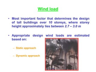
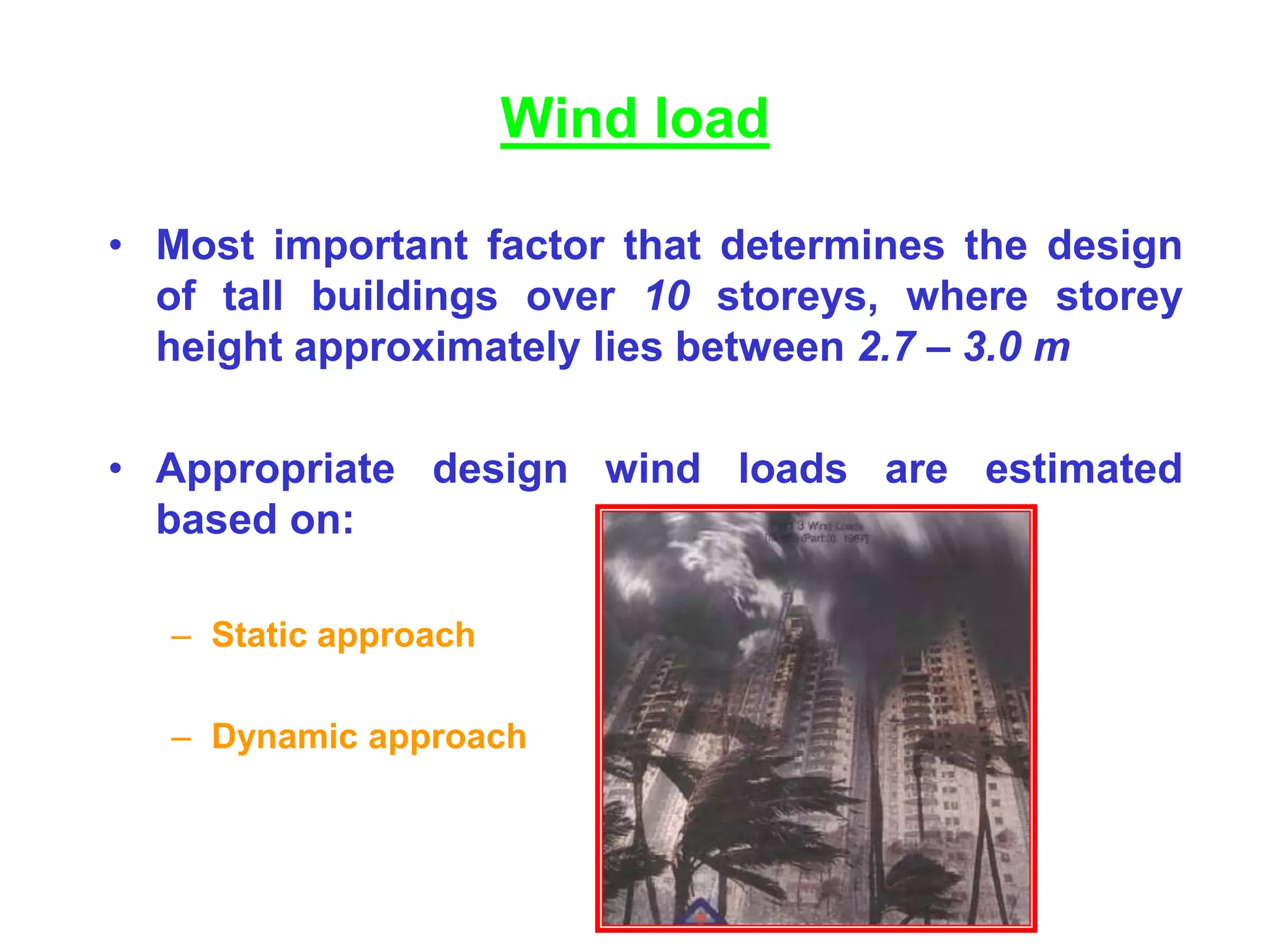
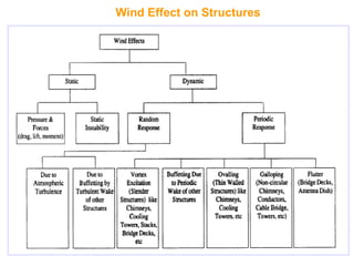
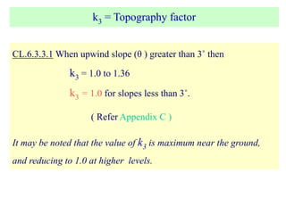
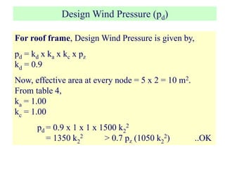
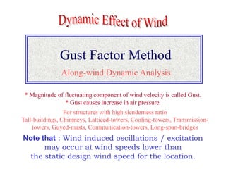
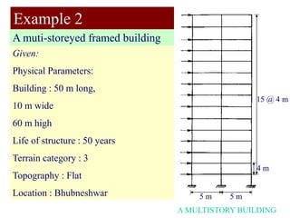
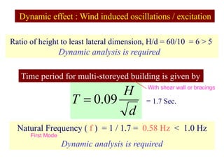
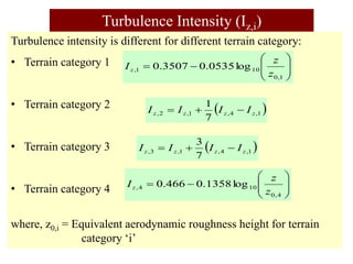
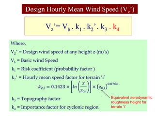
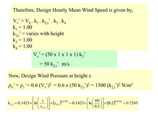
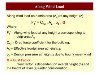
This document discusses wind load design for tall buildings. It states that wind load is the most important factor for buildings over 10 storeys tall. Wind loads are estimated using static and dynamic approaches. The document also provides guidance on instrumentation for monitoring wind data on tall structures, types of wind effects, dynamic wind analysis procedures, code provisions for wind speed and pressure calculations, and examples calculating wind loads using force coefficient and gust factor methods.

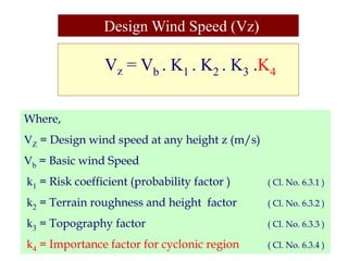
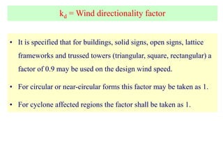
![Wind Load Calculations
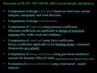
F= Cf Ae pd
a/b = 10/50= 0.2
h/b = 60/50= 1.2
Cf [refer Fig.4] = 1.2
Fig.4 : IS 875
a =10 m
b=50 m
Plan of building
a =10 m
h=60 m
Elevation
Frames @ 5m c/c
Frame
4m](https://image.slidesharecdn.com/wind-analysis-buildingsdas-230816161921-5c2d1847/85/Wind-Analysis-Building-Sdas-ppt-26-320.jpg)
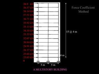
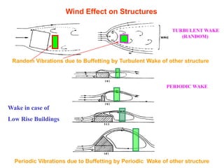
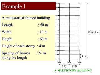
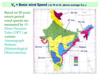
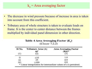
![Force coefficient for building
a/b = 10/50= 0.2
h/b = 60/50= 1.2
Cf ,z [refer Fig.4] = 1.2
Fig.4 : IS 875-P3
a =10 m
b=50 m
Plan of building
a =10 m
h=60 m
Elevation
Frames @ 5m c/c
Frame
4m
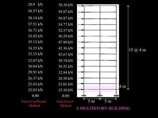
Effective frontal area at intermediate
level (Az) = 5 x 4 = 20 m2
At roof level = 5 x 2 =10 m2](https://image.slidesharecdn.com/wind-analysis-buildingsdas-230816161921-5c2d1847/85/Wind-Analysis-Building-Sdas-ppt-39-320.jpg)
![]
)
1
(
[
1
2
2
2
SE
g
H
B
g
r
G R
s
s
v
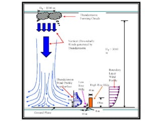
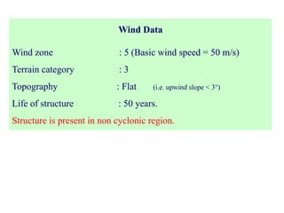
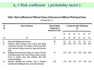
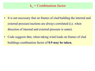
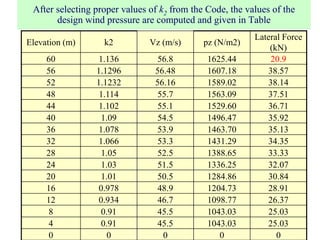
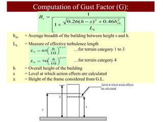
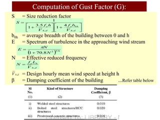
Where,
gv = Peak factor for upwind velocity fluctuation
= 3.0 for category 1 and 2 terrains and,
= 4.0 for category 3 and 4 terrains
r = Roughness factor
= 2 times longitudinal turbulence intensity, Ih,i (Cl.No. 6.5)
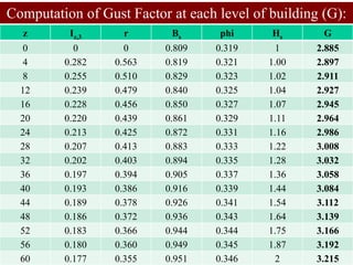
Computation of Gust Factor (G):](https://image.slidesharecdn.com/wind-analysis-buildingsdas-230816161921-5c2d1847/85/Wind-Analysis-Building-Sdas-ppt-40-320.jpg)
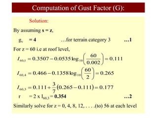
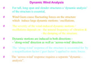
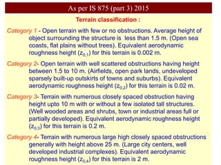
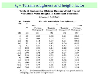
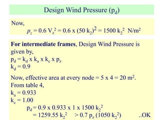
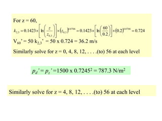
![Gust factor for s = 60,
Similarly solve for s = 0, 4, 8, 12, . . . .(to) 56 at each level to find gust
factor for different floor levels.
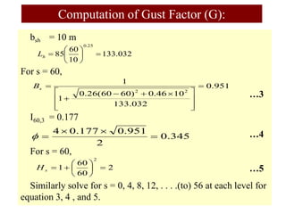
Computation of Gust Factor (G):
21
.
3
]
02
.
0
054
.
0
139
.
0
909
.
3
2
)
3458
.
0
1
(
9515
.
0
4
[
3545
.
0
1
2
2
2
G
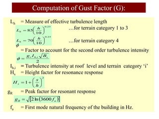
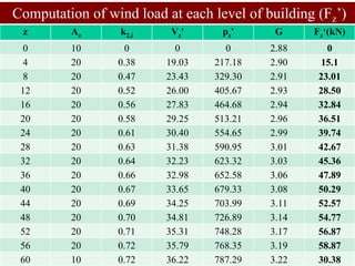
Along wind load (drag load) at roof top level
Fz’ = [ Cf,z . Az . pz
’ . G ] = 1.2 x 10 x 787.3 x 3.215 / 1000 = 30.37 kN
Similarly solve for s = 0, 4, 8, 12, . . . .(to) 56 at each level to find
lateral wind force for different floor levels.
Computation of Along Wind Load (Fz’):](https://image.slidesharecdn.com/wind-analysis-buildingsdas-230816161921-5c2d1847/85/Wind-Analysis-Building-Sdas-ppt-47-320.jpg)


![Geotechnical Engineering-II [Lec #7: Soil Stresses due to External Load]](https://cdn.slidesharecdn.com/ss_thumbnails/7-180930132739-thumbnail.jpg?width=640&height=640&fit=bounds)