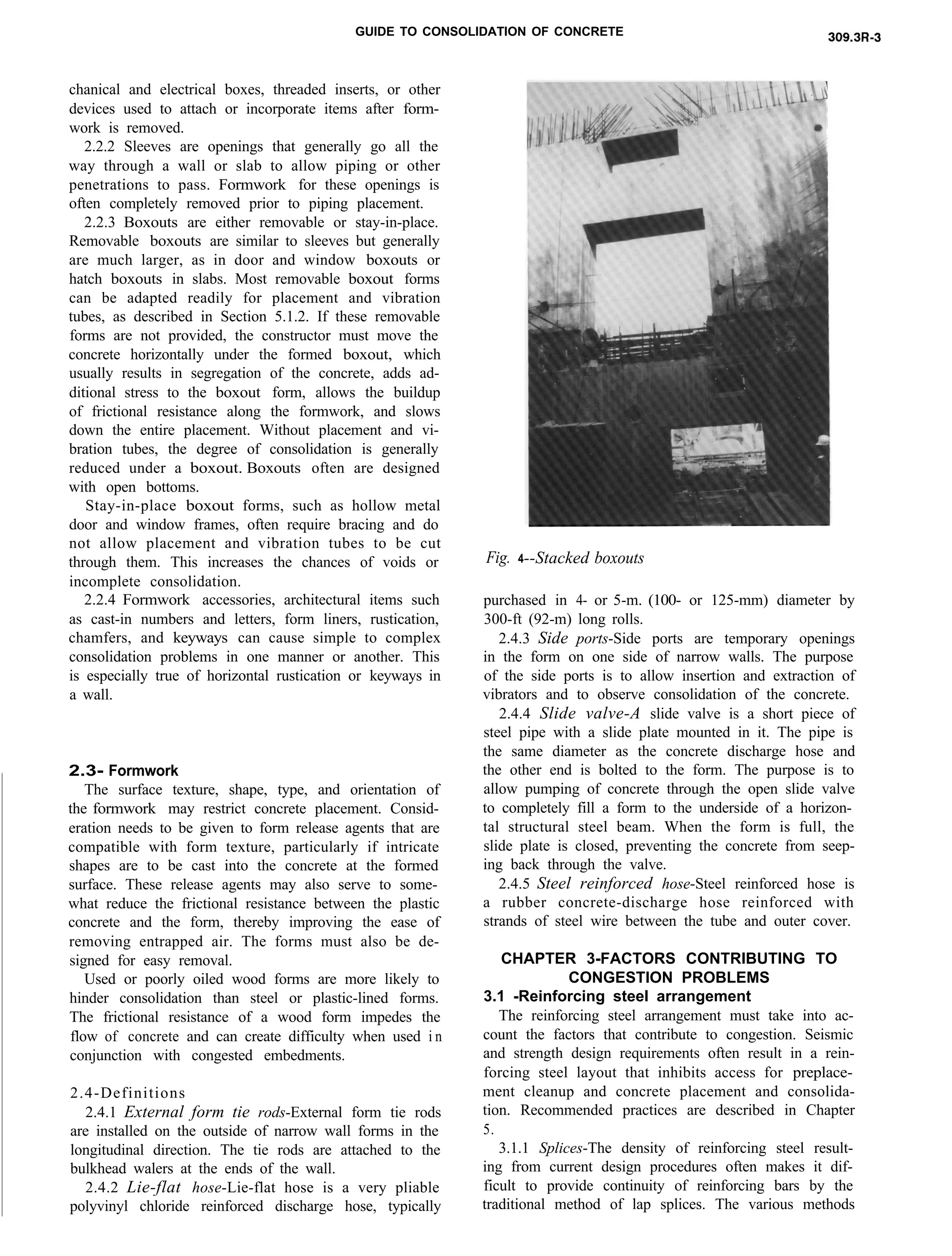
This document provides guidance on consolidating concrete in congested construction areas. It defines criteria for what constitutes a congested area, such as when reinforcement is spaced less than 1.5 times the maximum aggregate size. Factors contributing to congestion include dense reinforcement, embedded items like pipes and boxes, and formwork design. Congested areas can result in honeycombed or low-density concrete with increased cleaning, formwork and placement costs. The document recommends practices to address these issues, such as modified mix designs, placement methods, and design considerations that facilitate consolidation.
![309.3R-6 ACI COMMITTEE REPORT
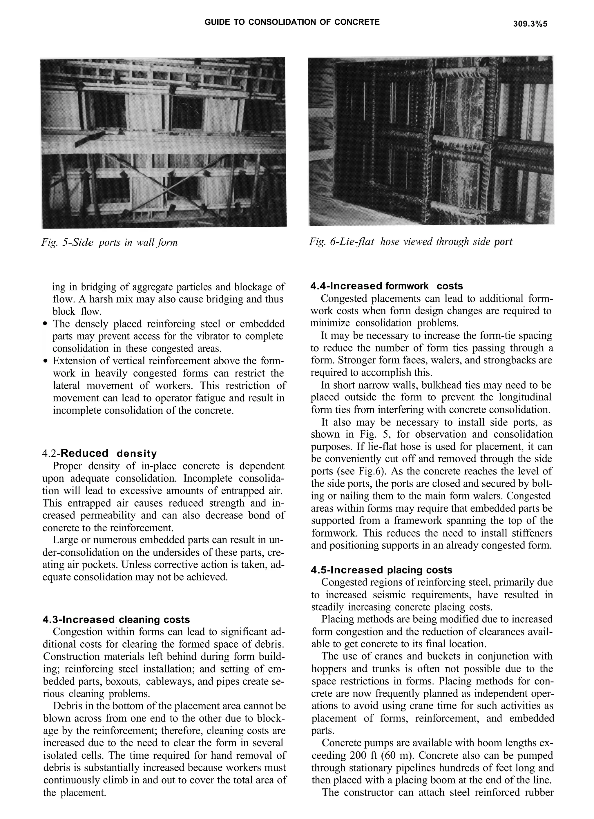
Fig. 7-Lie-flat hose coupled to concrete line
Fig. 8-Placement and vibration tubes: Large blockout
within a wall with pipes through the formed blockout
to permit access for concrete placement and vibration
hose up to 5 in. (125 mm) in diameter and 30 ft (9 m)
long to the end of the pump boom to get concrete to
the point of deposition. Fragile lie-flat hose is often re-
quired at the end of the rubber hose to get past extreme
congestion (see Fig. 7).
Where it is not possible for the vibrator operator to
insert the vibrator all the way to the bottom of wall
forms, the constructor should install side ports in the
form to allow lowering the vibrators through these
ports.
CHAPTER 5-RECOMMENDED PRACTICES
5.1 -Design considerations
5.1.1 Reinforcing steel arrangement-Arrangement
of reinforcing steel should provide enough space to al-
low concrete placement into the form. The architect/
engineer may have to increase the member size over
that required. by the design calculations so that suffi-
cient room is provided for placement.
In extreme cases, it may be necessary for the ar-
rangement to include accessways through the reinforc-
ing steel.
5.1.1.1 Reinforcement splicing methods-Until the
late 197Os, most reinforcing steel arrangements pro-
vided for lapping reinforcing steel bars without causing
undue congestion problems. More stringent seismic re-
quirements have resulted in a dramatic increase in the
amount of reinforcing steel per unit area, especially at
beam and column connections.
Lapping the bars would cause such severe congestion
that space between bars would almost disappear, re-
quiring a change to splicing.
Sometimes this congestion problem associated with
splicing can be solved by mechanically connecting the
reinforcing bars, as described by ACI 439.3R. In spe-
cial cases, the reinforcing bars may be spliced by
welded connections, provided that proper welding pro-
cedures are used considering the metallurgy of the re-
inforcing steels being joined. However, with either a
mechanical or welded connection, there will be some
localized increase in the reinforcement diameter, which
should be considered in detailing clearances and bar
spacing.
5.1.2 Embedded parts/boxouts-Embedment, sleeve,
and boxout configuration should consider reinforcing
details, concrete mix proportions, and especially the
nominal maximum size of aggregate. If possible, em-
bedments should be spread out.
Void forms should be used to eliminate form pene-
trations, but if they are large [more than 2 ft (0.6 m) in
either direction], a placement and vibration tube (see
Fig. 8) should be provided.
Boxouts that remain in place should have tolerances
to allow them to be shifted and placement and vibra-
tion tubes should be provided. Boxouts that are to be
removed and exceed 2 ft (0.6 m) in either direction also
should provide placement and vibration tubes.
In situations where the boxout spans from one form
face to the other, access should be provided through the
bottom of the boxout. As the concrete reaches the bot-
tom of the boxout, the access can be closed off with a
preformed insert, which is then bolted to the boxout
form.
5.1.3 Placing-The constructor must assess whether
his traditional placing methods will be adequate for the
job. Bidding merely on the total volume, average
placement size, and known project access conditions
can result in reduced profit margins. The constructor
must review reinforcing steel, embedment, and form-
work drawings to tailor the placing methods to suit the
conditions. The constructor may need to request
changes in the design of the placement or formwork to
obtain a quality product at a reasonable cost.
Increased cooperation between the architect/engi-
neer and constructor prior to beginning work will facil-
itate quality construction. Prebid and preconcreting
meetings to discuss all phases of the concrete work are
encouraged.](https://image.slidesharecdn.com/309-181105102354/75/309-3-r-92-guide-to-consolidation-of-concrete-in-congested-6-2048.jpg)
![5.2-Construction considerations
5.2.1 Use of admixtures-Proper placement of con-
crete in congested areas usually requires the concrete to
have flowing characteristics. Flowing concrete is gen-
erally considered to have a slump of 7% in. (190 mm)
or more, while remaining cohesive without excessive
bleeding or segregation (ACI 309R). The use of such
material permits placement and consolidation in areas
where less workable concrete mixtures cannot be prop-
erly placed and consolidated due to lack of mobility
and vibrator access.
Flowing concrete is commonly used in congested ar-
eas where the member itself is unusual in shape or size
or a large amount of reinforcement is present.
Since producing flowing concrete only by adding ex-
tra water results in lower quality concrete, such con-
crete should be obtained through the use of chemical
admixtures. Admixtures used to achieve flowing con-
crete should meet the requirements of ASTM C 494 and
ASTM C 1017. Commonly used materials for produc-
ing flowing concrete include:
1. High-range water-reducing admixtures (superplas-
ticizers), ASTM C 494, Types F or G.
2. A combination of high-range water-reducing ad-
mixtures plus a water-reducing and retarding admix-
ture, ASTM C 494, Type D, or water-reducing and ac-
celerating admixture, ASTM C 494, Type E.
3. High dosages of a water-reducing normal-setting
admixture, ASTM C 494, Type A, plus a water-reduc-
ing and accelerating admixture, ASTM C 494, Type E.
Where flowing concrete is required, trial mixtures
should be tested with materials representative of those
to be used in the project and under the environmental
conditions expected on the project. Trial mixtures
should be made using the initial slump resulting from
the maximum allowable specified water-cement ratio.
Chemical admixture dosages can be varied to achieve
the desired slump range. If necessary, the initial slumps
can be reduced by lowering the water-cement ratio and
thus improving the hardened properties of the con-
crete. Excessive retardation and loss of air content
should be avoided.
5.2.2 Use of modified mixtures (ACI 211.1 and
211.2)-Normally, architects/engineers will specify the
largest nominal maximum size aggregate mixtures that
are readily available and can be consolidated by con-
ventional placing methods. However, the need to meet
stringent seismic requirements has led architects/engi-
neers to make provisions in the specifications to use
smaller maximum size aggregate for some placements
or portions of placements. The architect/engineer
should consider this substitution based on the degree of
congestion of reinforcing steel or embedded parts.
As an example, when the concrete is specified with a
nominal maximum size aggregate of 1 l/2 in. (40 mm),
the architect/engineer may allow for substitution of a
portion of the concrete (in practice about 20 to 30 per-
cent) with %-in. (20-mm) nominal maximum size ag-
gregate (Bonikowsky).
Where the design mixture specifies nominal maxi-
mum size aggregate of 3/4 in. (20 mm) for extremely
congested areas, the architect/engineer ‘may allow sub-
stitution of a portion of the placement with nominal
maximum sized aggregate of 1/2 in. (13 mm). When the
maximum aggregate size of a specified mix is reduced,
the mix has to be modified by adjusting the water and
cement content to maintain the water-cement ratio and
design strength. Some specifications also allow the ad-
dition of fly ash to enhance workability. Typically, an
addition of fly ash equal to 5 percent of the cement
weight will provide excellent lubrication. At times, up
to 30 percent is allowed.
5.2.3 Formwork-Formwork design should be based
on full hydrostatic head conditions wherever practical.
Form-tie locations need to be considered when choos-
ing a form system and are often fixed in liquid head
forms. Full hydrostatic head forms often have large ties
[l-in. (25-mm) diameter or greater] and require place-
ment, pockets and cleanouts. Bulkhead design should
also consider full hydrostatic head. If longitudinal ties
or special corner ties are required, external ties should
be considered. Formwork accessories such as rustica-
tion, chamfers, and keyways should be considered in
reinforcement details, mix proportions, and placement,
as well as consolidation.
In general, formwork design should follow the prac-
tices and guidelines presented in ACI 303R and ACI
347R. Careful consideration should be given to areas of
congested reinforcement or other embedments. In ar-
eas of heavy congestion, concentrated vibration is likely
to occur that can increase the hydrostatic pressure on
the forms. When ‘needed, the spacing of load-bearing
members should be increased and combined with higher
capacity ties and sheathing. The use of external tie rods
in narrow congested walls also can help reduce the con-
gestion. When vertical access to the forms from the top
is limited and internal chutes cannot be used, side ports
should be incorporated to allow for the placement of
the concrete and consolidation by internal vibration.
Battered form faces or counterforts generally result
in areas of poor consolidation due to the problems of
placement, vibrator access, and restricted air migration
during vibration. The additional concrete required for
a vertical rather than sloped face may be highly cost-
effective if required repair of the formed surface is sig-
nificantly reduced.
Corbels and haunches generally are areas of conges-
tion. Similarity of shape and position can reduce form-
work costs.
5.2.4 Consolidation methods--Congestion is forcing
architects/engineers to take into consideration the con-
struction aspects of placing and consolidating quality
concrete. Some reinforcing steel arrangements are in-
corporating openings to provide access for cleaning,
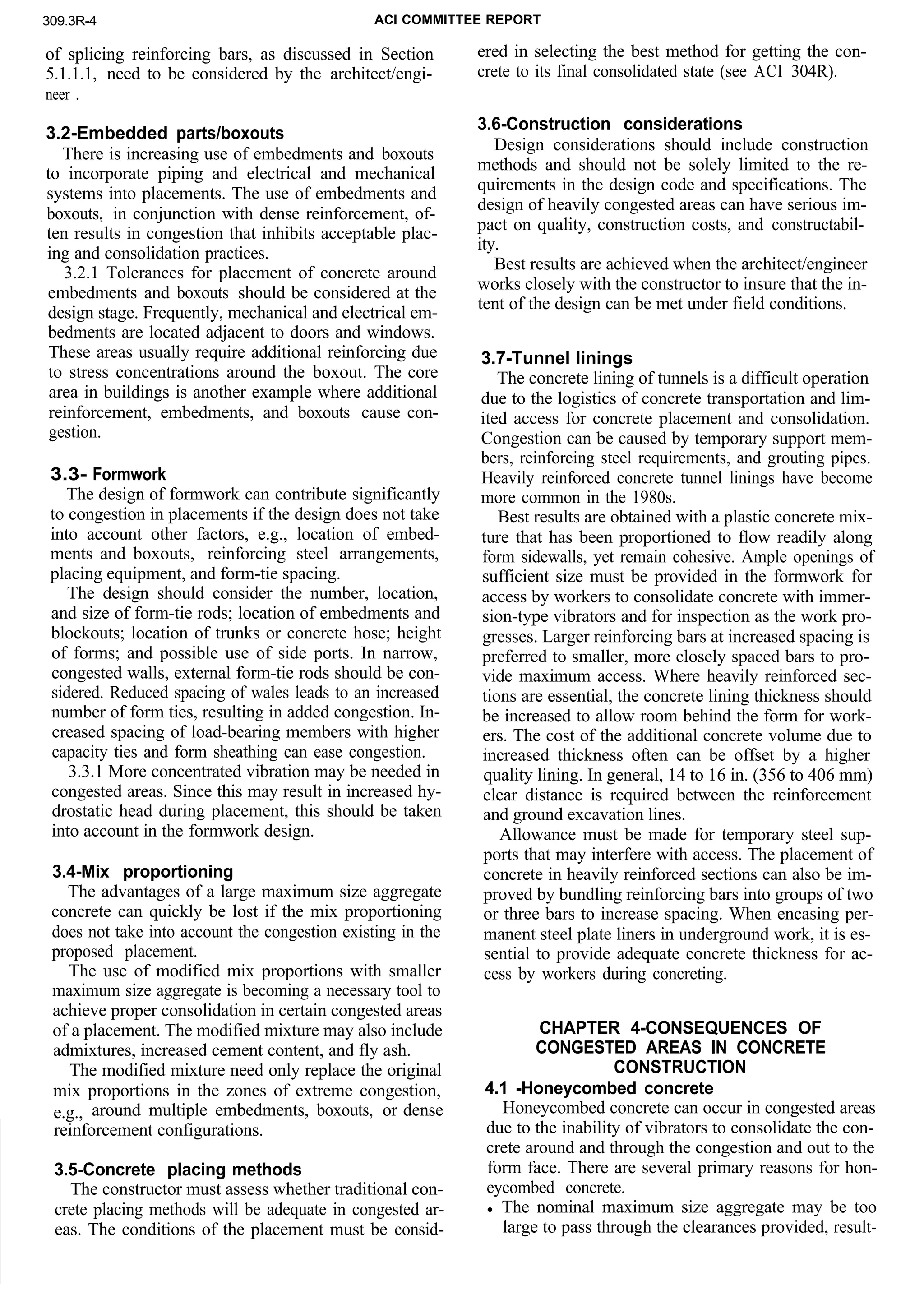
placing, and consolidation. Fig. 5 shows designed-in
accesses in a heavily reinforced wall section.
All aspects of the consolidation operation in con-
gested forms should be well planned prior to start of
the concrete placement. Smaller size vibrators may be
used in the lower areas within the forms when a high-](https://image.slidesharecdn.com/309-181105102354/75/309-3-r-92-guide-to-consolidation-of-concrete-in-congested-7-2048.jpg)
![309.3R-8 ACI COMMITTEE REPORT
Fig. 9-Slide valves for pressure pumping of narrow
congested walls to the underside of horizontal struc-
tural steel beams
range water-reducing admixture is used with a modi-
fied concrete mixture as described in Section 5.2.2.
When it is reasonable to return to the normal concrete
mixture using larger maximum size aggregate, bigger
and more effective vibrators [typically up to 3 in. (75
mm) in diameter] should be used.
When access into the form by the placing crew is
limited due to reinforcing steel, additional vibrators
should be lowered down through the upper reinforcing
mat from the top of the placement. This practice will
reduce the tendency of operators to try to throw the vi-
brators horizontally past interferences and will encour-
age them to operate vibrators in a nearly vertical posi-
tion.
If the constructor is using pneumatic vibrators, he
should insure a good supply of compressed air with
headers located near the form. Oilers should be
mounted on each line coming off the air header. He
should also provide sufficient spare vibrators in the
event of a vibrator breakdown. Adequate power should
also be provided for electric vibrators.
In congested narrow wall forms, it may be necessary
to place side ports in one of the wall forms. The side
ports are typically 2 ft (0.6 m) square with a spacing of
6 ft (1.8 m). The side ports are used to lower the vibra-
tors into the form and to observe the concrete placing
within the form. This is necessary to insure that bridg-
ing of the concrete during placement has not occurred.
It may also be possible to lower small-diameter vibra-
tors between the outer layer of reinforcement and the
form face, except in the case of architectural faces,
where external form vibrators should be used. External
form vibrators are discussed in ACI 309R, Chapter 5,
and formwork considerations are discussed in SP-4,
Chapter 5.
Due to the increased time required for congested
placements, it may be necessary to use high-range wa-
ter-reducing and retarding admixtures or a high-range
water-reducing admixture with extended slump reten-
tion. Great care must be taken by the operator not to
lodge or snag the vibrator within the placement be-
cause it can become virtually impossible to extract.
The constructor and inspector must be aware that it
is a far lesser evil to overvibrate than to undervibrate
due to the risk of honeycombed concrete, air pockets,
and lack of density in congested areas.
5.2.5 Placing methods-Congested forms and diffi-
cult placing conditions have resulted in drastic changes
in placing methods. Concrete pumping or conveyors are
used more frequently than crane and bucket under such
conditions. The prime means of insuring good consoli-
dation continues to be the ability to place concrete as
close to its final position as possible.
The majority of concrete placed in congested forms
is placed by pump booms or placing booms using 4- or
5-in. (100- or 125-mm) diameter steel reinforced hose.
To insure good pumpability, the architect/engineer is
usually restricted to a maximum of l1/2-in. (40-mm)
nominal maximum size aggregate.
The majority of concrete in congested forms can be
placed by lowering the concrete hose through the rein-
forcement to within 6 ft (1.8 m) of the surface, dis-
charging the lift thickness, then raising and reinserting
the hose at typically 10-ft (3-m) centers.
In narrow wall forms where it is not possible to lower
the concrete hose through the reinforcement, lie-flat
hose coupled to the steel reinforced hose has been used
successfully. The lie-flat hose is very pliable and can
transfer concrete vertically through very narrow spaces.
The hose is relatively inexpensive, making it economi-
cal to cut off for removal from the placement if it be-
comes caught on reinforcement or embedments (see
Fig. 7).
Where wall placements extend up to the underside of
structural steel members or concrete beams, concrete
should be placed under pressure through slide valves, as
depicted in Fig. 9. When the form is full, the slide valve
is closed and the line disconnected. After the concrete
has set, the slide valve and supporting form are re-
moved. The remaining concrete stub is removed by
chipping and the wall is ground smooth.
Pumping concrete from the bottom of the form can
offer a solution to congestion in some instances. Flow-
ing concrete is recommended for use with this method.
The shape of the element has a great deal to do with
whether or not the technique is viable. Rectangles,
squares, and other polygons require special design of
formwork because pressure concentrates at the corners
of angles or point loading is developed. Circular unres-
tricted structures lend themselves best to pumping from
the bottom. Unrestricted means that the concrete must
be unimpeded all the way around the inside of the col-
umn and there are no baffles that restrict upward
movement.
If there is a vertical steel “H” section within the col-
umn, the concrete will not pump if the concrete enters
at a point perpendicular to one of the flanges of the
“H.” If concrete is discharged directly into the web of](https://image.slidesharecdn.com/309-181105102354/75/309-3-r-92-guide-to-consolidation-of-concrete-in-congested-8-2048.jpg)
![GUIDE TO CONSOLIDATION OF CONCRETE 309.3R-9
the “H,” the concrete will pump. This effect is dimin-
ished when at least 12 in. (300 mm) of concrete cover
over the “H” is present. Successful pumping has been
achieved with less than 4-in. (lOO-mm) cover if pumped
into the web.
When pumping from the bottom, there should be re-
strictions on the number and size of embedments or
boxouts and their position in the form. Also, if there
are large numbers of dowels, the flow of concrete may
be restricted, causing pump and/or form failures. At
least a 4-in. (lOO-mm) clearance should be provided be-
tween the embedment and the reinforcement or 4 in.
(100 mm) free at the top of the placement below the
structural steel or turned out reinforcement.
Preplaced aggregate (PA) is another placing method
that has been used effectively in congested areas. To
produce concrete by the PA method, coarse aggregate
is first placed in the prepared form. Then the voids in
the preplaced aggregate are filled with a fluid grout
consisting of cement, sand, water, and sometimes an
admixture, which is pumped into the forms from the
bottom through form inserts or pipes. Materials re-
quirements, procedures, and properties are described in
ACI 304.1R.
The PA method has been used to advantage for
placing concrete around congested reinforcement.
Where the reinforcing steel and forms are already in
place, grout pipes are inserted from the top or sides to
the bottom of the space to be filled. Coarse aggregate
is then dropped into place or shoved in from the sides,
and assisted by rodding and/or blowing with the help
of air lances.
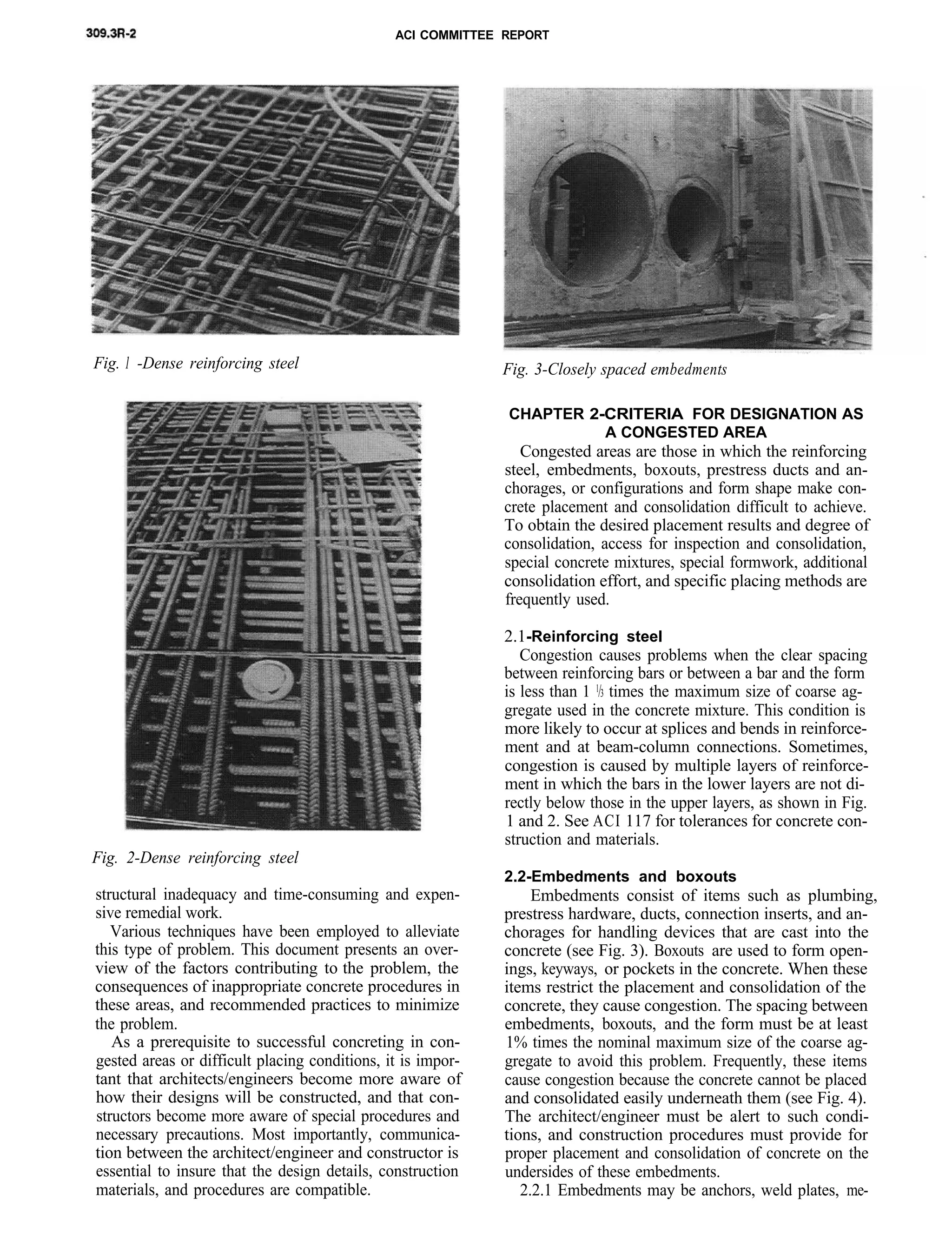
After the form has been completely filled with aggre-
gate, the grout is pumped into the forms. Alterna-
tively, the coarse aggregate may be placed in lifts as the
reinforcement and forms are erected. Fig. 10 shows a
portion of a boxout left in the side of a nuclear con-
tainment structure 50 ft long by 35 ft wide by 6 ft thick
(15.2 x 10.6 x 1.8 m). The reinforcement placed during
initial construction was too congested to permit the use
of vibrators, especially because the rear wall was a steel
membrane that could not be cut to receive ports. The
boxout was filled with PA concrete in 7-ft (2.1-m) lifts.
The preplaced aggregate method provides three plac-
ing advantages:
1. There is no time limit on placing the coarse aggre-
gate.
2. Areas that do not contain aggregates due to bridg-
ing are not critical because all spaces are filled with
grout having approximately the same strength as the
surrounding concrete. The PA method can signifi-
cantly reduce the chances of honeycomb.
3. Continuous pumping of the grout eliminates cold
joints. However, if pumping is interrupted for any rea-
son, the effect of the cold joint that forms is negligible
because coarse aggregate particles extending through
the grout surface provide structural continuity across
the interface between the two grout placements with a
high probability that the negative effects of the cold
joint can be minimized or eliminated.
Fig. IO-Preplaced aggregate method: Close-up of
congested reinforcement in blockout in side of a con-
tainment structure. Grout inserts [l-in. (25mm) diam-
eter pipes] are shown in right center (one uncapped)
and near bottom (two, temporarily capped). Top of
first lift of coarse aggregate [approximately 7 ft (2.1 m)
deep] is visible at bottom of photo. Grout will be
pumped to a few inches below surface of the coarse ag-
gregate to provide a keyed joint with the succeeding lift
Disadvantages of the PA method include the diffi-
culty of isolating congested sections to be placed mon-
olithically from less heavily reinforced concrete. PA
concrete may be somewhat time-consuming and labor-
intensive.
5.3-Summary
Successful concreting under difficult conditions or in
highly congested sections requires an effective combi-
nation of design, placement, and consolidation tech-
niques. While this document has presented a number of
options that can be considered by architects/engineers
and constructors, it must be recognized that each situ-
ation may be unique. The architect/engineer and con-
structor, in consultation with each other, must assess
each situation and agree on the most appropriate ap-
proach for the situation in question. However, it is of
utmost importance that situations requiring special at-
tention be identified with sufficient lead time to allow
proper planning.
CHAPTER 6-REFERENCES
6.1 -Specified and/or recommended references
The documents of the various standards-producing
organizations referred to in this document are listed
with their serial designations.
These publications
ing organizations:
may be obtained from the follow-](https://image.slidesharecdn.com/309-181105102354/75/309-3-r-92-guide-to-consolidation-of-concrete-in-congested-9-2048.jpg)