Paper
•Download as DOCX, PDF•
0 likes•301 views

This document summarizes a case study on an engine tripping problem in an engine used at XYZ Resources Ltd. due to seasonal temperature variations. During training, the author observed the G3412TA engine would frequently trip without warning on hot days, shutting down the plant for 1.5 hours. Potential causes investigated included high ambient temperatures, insufficient coolant flow, and faulty sensors. The document concludes the problem is likely caused by high inlet air temperatures and insufficient coolant flow. It recommends installing a better engine room ventilation system per Caterpillar guidelines to address high temperatures as a solution.
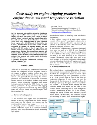
![Figure. 1 Block diagram of cooling
system
Table 1. Engine parameter by company
peed 1800 Tripping Parameter Set Value
137 mm (5.4 in.) Compressor suction pressure 0.5 bar
152 mm (6.0 in.) Compressor discharge pressure 19.5 bar
ment 27.0 L (1649 cu. in.) Oil filter differential pressure 20 PSI
der 1-8-4-3-6-5-7-2 Compressor oil header pressure 1.20 bar
n Turbocharged-After
cooled
Compressor discharge temp. 85⁰c
eight 2143 kg (4720 lb) Oil separator1 level 25%
ion ratio 8.5:1 Oil separator2 level 5%
ystem Digital Ignition Oil pump discharge temperature 80⁰c
type Woodward 2301A Engine oil level 25%
ater (°F) 210 Engine oil pressure 10 PSI
ler (°F) 130 Engine oil temp. 106.1⁰c
Pressure 1.5 psig Jacket water pump inlet 86⁰c
e Lash 0.38 mm Turbo water level 2.50%
Valve Lash 1.02 mm Turbo water temp 150⁰c
Oil separator sump temp. 80⁰c
Engine speed 1836
As shown in table 1, during our summer training
we found problem in ‘Jacket Water Cooling
System’. Normally engine trips if temperature of
jacket water exceeds then 86 ⁰c or its level reduce
up to 2.50%.But in hot day’s engine trips due to
warning with problem in jacket water. But when
we checked manually jacket water temperature
and jacket water level both were in their normal
value.
3 PROBLEM
From literature review and during our training
period we observed some of the causes which are
responsible for faulty cooling system. Following
are the list of causes.
1] High Ambient temp / high inlet air temp 2]
Low coolant level
3] Faulty water sensor 4]
Faulty water temp regulator
5] Excessive load 6]
Incorrect ignition timing
7] Insufficient flow of coolant through the engine
Among all 7 causes company refused cause no.
2,3,4,6, and 7.Reason of refusing it is as follows:
Table 2. Problem causes and action taken
by
company
Low coolant level They fill coolant according to thei
the time of failure they observe suff
Faulty water sensor
They have cross verified the J/W
elements at different location, In ac
Faulty water temp. regulator
They have bypassed the thermostat
up to 100℃ and also they replace
problem occurs.
Excessive load
In the company engine runs all the
of load recommended by the manuf
Incorrect ignition timing
There is no any chance of incorr
runs engine as per specification-28°
So in this project we worked on the cause ‘High
Ambient temp / high inlet air temp’ which may
be responsible for the failure of cooling system.
Solution for this cause is as follows.
4.1 Engine Room Ventilation
This research addresses engine room ventilation
considerations that apply to the successful
installation, operation and maintenance of
Caterpillar engines, generator sets, compressor
units, and other packaged units. The primary
aspects of a properly designed engine room
ventilation system are cooling air and combustion
air. Cooling air refers to the flow of air that
removes radiant heat from the engine, generator,
other driven equipment and other engine room
components. Combustion air describes the air the
engine requires to burn fuel.
4.2 Sizing Considerations
4.2 (I) Cooling Air
A portion of fuel consumed by an engine is lost to
the environment in the form of heat radiated to the
surrounding air. In addition, heat from generator
inefficiencies and exhaust piping can easily equal](data:image/gif;base64,R0lGODlhAQABAIAAAAAAAP///yH5BAEAAAAALAAAAAABAAEAAAIBRAA7)
Recommended
Recommended
More Related Content
What's hot
What's hot (20)
Similar to Paper
Similar to Paper (20)
Paper
- 1. Case study on engine tripping problem in engine due to seasonal temperature variation Ganesh Chouhan1 1Department of Mechanical Engineering, Vidhyadeep institute of management and Technology, Anita,Kim, India. (ganesh_chouhan31@yahoo.com) In XYZ Resources Ltd. numbers of internal combustion engines are used. Most of those engines are four stroke engines working on Otto cycle in which natural gas is used as fuel. All the engines in XYZ are made by Caterpillar Inc. and each has some distinct functions to perform. While going under training at XYZ, we found a problem in an engine called G3412TA made by Caterpillar Inc. G3412TA, found in Dew Point Control Unit is used for circulation of propane for cooling purpose. But the problem with this engine is that it trips without any tripping warning specially in hot days it trips frequently and hence the plant has to be shut off for at least one and half hour. Thus the problem proves very uneconomic for company. During the whole curriculum we examined and evaluated the problem and tried to rectify the feasible solutions for the same. Keywords: manifold, combustion, cooling system, exhaust gas. I. INTRODUCTION There may be problem in any component of the cooling system. The component involved in cooling system of the engine is radiator; radiator cooling fans, water pump, engine block, thermostat, hoses, etc. Various sensors are provided for measuring the various parameters like temperature of the coolant, level of the coolant, pressure at the outlet of the water pump. These sensors sense respective parameter and sends information about them to the ECM. Engine has some tripping parameters. If any of them fullfill tripping condition, engine will automatically trip. These tipping points are sets for secure the parts of engine, plant assets, workers life. A. Purpose of cooling system As fuel is burned in the engine, about one-third of the energy in the fuel is converted into power. Another third goes out the exhaust pipe unused, and the remaining third becomes heat energy. 1. A cooling system of some kind is necessary in any internal combustion engine. If no cooling system were provided, parts would melt from the heat of the burning fuel, and the Tushar N. Desai2 2Department of Mechanical Engineering, S.V. National Institute of Technology, Surat, India, (tushardesaisvnit@gmail.com) pistons would expand so much they could not move in the cylinders. 1. The cooling system of a water-cooled engine consists of: the engine's water jacket, a thermostat, a water pump, a radiator and radiator cap, a cooling fan (electric or belt-driven), hoses, the heater core, and usually an expansion (overflow) tank. 2. Fuel burning engines produce enormous amounts of heat; temp. can reach up to 4,000 °F when the air-fuel mixture burns. However, normal operating temperature is about 2,000 °F. The cooling system removes about one-third of the heat produced in the combustion chamber. The exhaust system takes away much of the heat, but parts of the engine, such as the cylinder walls, pistons, and cylinder head, absorb large amounts of the heat. If a part of the engine gets too hot, the oil film fails to protect it. 2. Working of cooling system The coolant follows a path that takes it from the water pump, through passages inside the engine block where it collects the heat produced by the cylinders. Then flows from bottom to top of the cylinder head (or heads in a V type engine) where it collects heat from the combustion chambers. It then flows out past the thermostat (if the thermostat is opened to allow the fluid to pass), through the upper radiator hose and into the radiator. The coolant flows through the thin flattened tubes that make up the core of the radiator and is cooled by the air flow through the radiator. From there, it flows out of the radiator, through the lower radiator hose and back to the water pump. By this time, the coolant is cooled off and ready to collect more heat from the engine. Exhaust manifold Engine Head Engine Block Oil Cooler Jacket Water Pump Thermostat Radiator
- 2. Figure. 1 Block diagram of cooling system Table 1. Engine parameter by company peed 1800 Tripping Parameter Set Value 137 mm (5.4 in.) Compressor suction pressure 0.5 bar 152 mm (6.0 in.) Compressor discharge pressure 19.5 bar ment 27.0 L (1649 cu. in.) Oil filter differential pressure 20 PSI der 1-8-4-3-6-5-7-2 Compressor oil header pressure 1.20 bar n Turbocharged-After cooled Compressor discharge temp. 85⁰c eight 2143 kg (4720 lb) Oil separator1 level 25% ion ratio 8.5:1 Oil separator2 level 5% ystem Digital Ignition Oil pump discharge temperature 80⁰c type Woodward 2301A Engine oil level 25% ater (°F) 210 Engine oil pressure 10 PSI ler (°F) 130 Engine oil temp. 106.1⁰c Pressure 1.5 psig Jacket water pump inlet 86⁰c e Lash 0.38 mm Turbo water level 2.50% Valve Lash 1.02 mm Turbo water temp 150⁰c Oil separator sump temp. 80⁰c Engine speed 1836 As shown in table 1, during our summer training we found problem in ‘Jacket Water Cooling System’. Normally engine trips if temperature of jacket water exceeds then 86 ⁰c or its level reduce up to 2.50%.But in hot day’s engine trips due to warning with problem in jacket water. But when we checked manually jacket water temperature and jacket water level both were in their normal value. 3 PROBLEM From literature review and during our training period we observed some of the causes which are responsible for faulty cooling system. Following are the list of causes. 1] High Ambient temp / high inlet air temp 2] Low coolant level 3] Faulty water sensor 4] Faulty water temp regulator 5] Excessive load 6] Incorrect ignition timing 7] Insufficient flow of coolant through the engine Among all 7 causes company refused cause no. 2,3,4,6, and 7.Reason of refusing it is as follows: Table 2. Problem causes and action taken by company Low coolant level They fill coolant according to thei the time of failure they observe suff Faulty water sensor They have cross verified the J/W elements at different location, In ac Faulty water temp. regulator They have bypassed the thermostat up to 100℃ and also they replace problem occurs. Excessive load In the company engine runs all the of load recommended by the manuf Incorrect ignition timing There is no any chance of incorr runs engine as per specification-28° So in this project we worked on the cause ‘High Ambient temp / high inlet air temp’ which may be responsible for the failure of cooling system. Solution for this cause is as follows. 4.1 Engine Room Ventilation This research addresses engine room ventilation considerations that apply to the successful installation, operation and maintenance of Caterpillar engines, generator sets, compressor units, and other packaged units. The primary aspects of a properly designed engine room ventilation system are cooling air and combustion air. Cooling air refers to the flow of air that removes radiant heat from the engine, generator, other driven equipment and other engine room components. Combustion air describes the air the engine requires to burn fuel. 4.2 Sizing Considerations 4.2 (I) Cooling Air A portion of fuel consumed by an engine is lost to the environment in the form of heat radiated to the surrounding air. In addition, heat from generator inefficiencies and exhaust piping can easily equal
- 3. engine-radiated heat. Any resulting elevated temperatures in the engine room may adversely affect maintenance, personnel, switchgear, and engine or generator set performance. Engine room ventilation air (cooling air) has two basic purposes. • To provide an environment that permits the machinery and equipment to function properly with dependable service life. • To provide an environment in which personnel can work comfortably and effectively. 4.2 (II) Combustion Air In many installations, combustion air is drawn from outside the engine room via ductwork that is designed to move a large amount of air with very little restriction. These installations have very little impact on engine room ventilation design. Other installations, however, require that combustion air be drawn directly from the engine room. In these installations, combustion air requirements become a significant ventilation system design parameter. 4.2 (III) Ventilation Airflow Calculation required for ventilation airflow Engine room ventilation air required for Caterpillar engines and packages can be estimated by the following formula. V =[ 𝐻 𝐷×𝐶𝑝×∆𝑇 + 𝐶𝑢𝑚𝑏𝑢𝑠𝑡𝑖𝑜𝑛 𝐴𝑖𝑟] × F Where: F = Routing factor based on the ventilation type discussed in the Routing Considerations section of this guide. 4.2 (IV) Engine Room Temperatures The primary reason for maintaining engine room temperature at an appropriate level is to protect various components from excessive temperatures. Items that require cool air are: • Electrical and electronic components. • Cool air to the air cleaner inlet. • Cool air to the torsional vibration damper. • Habitable temperatures for the engine operator or service personnel. • Cooling air for the generator or other driven equipment. A properly designed engine room ventilation system will maintain engine room air temperatures within 8.5 to 12.5°C (15 to 22.5°F) above the ambient air temperature. For example, if the engine room temperature is 24°C (75°F) without the engine running, the ventilation system should maintain the room temperature between 32.5°C (90°F) and 36.5°C (97.5°F) while the engine is in operation. Maximum engine room temperature should not exceed 49°C (120°F). If the engine room temperature cannot be maintained below 49°C (120°F), outside air should be ducted directly to the engine air cleaners. 4.2 (V) Atmospheric Heat Rejection Correction Factor There are two distinct correction factors, one is used with wet exhaust and turbo manifolds, the other is used with dry exhaust and turbo manifolds. The skin temperature utilized in the dry manifold calculation is 200°C, approx value of the wrapped or insulated manifold. Wet exhaust and turbo manifold correction factor. WCF = -.0156 * T ER + 1.4505 Dry exhaust and turbo manifold correction factor. DCF = -.011* T ER +1.3187 To obtain the corrected atmospheric heat rejection value, multiply the TMI value by the WCF or DCF. 4.3 (I) Fan Locations Fans are most effective when they withdraw ventilation air from the engine room and exhaust the hot air to the atmosphere. However, ideal engine room ventilation systems will utilize both supply and exhaust fans. This will allow the system designer the maximum amount of control over ventilation air distribution. The fan motors should be mounted outside the direct flow of hot ventilating air for longest motor life. The design of centrifugal fans (squirrel cage blowers) is ideal in this regard, but their size, relative to the vane-axial or tube-axial fans, sometimes puts them at a disadvantage [14]. 4.3 (III) Fan Sizing
- 4. Fan sizing involves much more than just selecting a fan that will deliver the airflow volume needed to meet the cooling air and combustion air requirements. It requires a basic understanding of fan performance characteristics and ventilation system design parameters. Similar to a centrifugal pump, a fan operates along a specific fan curve that relates a fan’s volume flow rate (m 3 /min or cfm) to pressure rise (mm H 2 O or in. H 2 O) at a constant fan speed. Therefore, fan selection not only requires that the volume flow rate be known, but also that the ventilation distribution system be known in order to estimate the system pressure rise. This information allows the optimum fan to be selected from a set of manufacturers’ fan curves or tables. 4.3 (IV) Exhaust Fans Ventilation air exhaust systems should be designed to maintain a slight positive or negative pressure in the engine room, depending on the specific application. Positive pressure should normally not exceed 0.050 kPa or (0.2 in. H 2 O). This positive pressure provides the following advantages. It prevents the ingress of dust and dirt, which is especially beneficial for those applications involving engines that draw their combustion air from the engine room. It creates an out draft to expel heat and odour from the engine room. 4.4 Routing Considerations 4.4 (I) General Routing Principles Fresh air inlets should be located as far from the sources of heat as practical and as low as possible. Ventilation air should be exhausted from the engine room at the highest point possible, preferably directly over the engine. Ventilation air inlets and outlets should be positioned to prevent exhaust air from being drawn into the ventilation inlets (recirculation). Ventilation air inlets and outlets should be positioned to prevent pockets of stagnant or re- circulating air, especially in the vicinity of the generator air inlet. 4.4 (II) Single & Dual Engine Applications These applications will generally require smaller engine rooms, which are especially challenging in regard to the use of good routing practices Ventilation Type 1 (Preferred Design) Outside air is brought into the engine room through a system of ducts. These ducts should be routed between engines, at floor level, and discharge air near the bottom of the engine and generator as shown in Figure 2. Ventilation air exhaust fans should be mounted or ducted at the highest point in the engine room. They should be directly over heat sources. This system provides the best ventilation with the least amount of air required. In addition, the upward flow of air around the engine serves as a shield which minimizes the amount of heat released into the engine room. Air temperature in the exhaust air duct will be higher than engine room air temperature. Figure 2. Ventilation type 1 5 CONCLUSION As explained in ‘solution of problem’, during our industrial training and our project work we found some of causes which may be responsible for faulty cooling system. During our project time we suggest causes of problem like faulty water level sensor, faulty thermostat, incorrect ignition timing, and excessive load to the company. Above causes of problem are refused by them because they already replaced the elements by new one though problem is still arise. So now there is only two causes which are responsible for the problem like High Ambient temp / high inlet air temp and Insufficient flow of coolant through the engine. We can’t find any solution for ‘Insufficient flow of coolant through the engine’ but we have a solution which may be help to solve the problem, which is
- 5. ‘Providing Better Engine Room Cooling Air Ventilation System’. We obtain design of the preferred, skid, alternative and less effective ventilation system from caterpillar ventilation manual. At the problem place none of the above listed ventilation system is establish. So, if they accept one of the ventilation system there is chance of overcoming the problem. REFERENCE (1) Influence of ambient condition on performance of gas engine, Position-Paper By The Cimac Working Group ”Gas Engines”, March 2009. (2) Fluid level & temp. Monitoring and alarm system by Raymond A. proulx, Barrington N.H, United States Patent, patent no- 5,708,412. Date of patent: Jan.13, 1998. (3) Sensor assembly for a radiator mounted coolant level monitoring system by Boris Puscasu, Dearborn Heights, Mich. United States Patent, patent no-4,638,291, Date of Patent Jan.20, 1987. (4) Project Paper High Efficiency Radiator Design for Advanced Coolant Brandon Fell & Scott Janowiak, Fall 2007 (5) http://www.coolingtower- design.com/2011/05/05/radiator-cooling- system-04 (6) Niko Tripping parameter sheet (7) http://www.worktrucksales.com/infocooling. htm