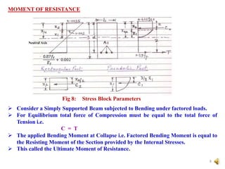
This document provides an introduction to singly reinforced concrete beam sections. It discusses the stresses induced in beams due to bending moments, including compression and tension zones. It defines key terms like the neutral axis and neutral surface. The document then covers assumptions made in design, calculation of the moment of resistance considering the forces of compression and tension, and limiting the depth of the neutral axis to prevent brittle failure. It also discusses under-reinforced and over-reinforced beams and their failure modes. Tables provide limiting values for moment capacity, depth of neutral axis, and steel reinforcement percentages for different concrete and steel grades.
![SINGLY REINFORCED SECTIONS - [ BEAMS ]
4
A
A
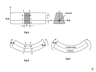
NA
Tension
Compression
Clear Span
b
D d
A Reinforced Concrete Flexure Member should be able to resist the following
stresses induced due to Imposed Loads :
Tensile Stress
Compressive Stress
Shear Stress
Concrete :-
Fairly Strong in Compression
Weak in Tension
Tensile Strength taken as Zero
Steel:-
Very Strong in Tension
Steel takes up Tension in the Tensile Zone of the Flexural Member.](https://image.slidesharecdn.com/1-singlyreinforcedsections-beams-audio-220611125802-b21ba99b/85/1-Singly-Reinforced-Sections-Beams-AUDIO-pptx-4-320.jpg)
![ While Designing a Reinforced Concrete Section, the Loading, Span, Grade of
Concrete, Grade of Steel and Width of Section are usually known in advance.
The Section Dimensions and Area of Steel Bars [Reinforcing Steel] are to be
determined.
There can be no unique section for a given set of forces. There are many
possible combinations.
Thus the cost will decide the final design
5](https://image.slidesharecdn.com/1-singlyreinforcedsections-beams-audio-220611125802-b21ba99b/85/1-Singly-Reinforced-Sections-Beams-AUDIO-pptx-5-320.jpg)
![ASSUMPTIONS
Design for the Limit State of Collapse in Flexure shall be based on the assumptions
as per IS 456 – 2000; Clause 38.1, p 69
Plane Sections Normal to the Axis remain Plane after Bending
The Maximum Strain in Concrete at the outermost Compression Fibre is taken as
0.0035 in Bending
The Relationship between Stress-Strain distribution in Concrete is Parabolic upto
a Strain of 0.002 and then constant upto a Strain of 0.0035 at which the concrete is
said to have failed [IS 456 – 2000, Fig 21, pp. 69]
For Design purpose the Compressive Strength of Concrete is taken as 0.67 times
the Characteristic Strength of Concrete. A Partial Safety Factor m = 1.5 shall be
applied in addition to this.
The Tensile Strength of Concrete is ignored
The Stress in the Reinforcement is derived from the representative Stress-Strain
Curve for the type of Steel used. The typical Curves are given in Fig 23 of IS 456 –
2000; pp. 70
For Design Purposes the Partial Safety Factor of m = 1.15 shall be applied to the
Characteristic Strength of Steel
6](https://image.slidesharecdn.com/1-singlyreinforcedsections-beams-audio-220611125802-b21ba99b/85/1-Singly-Reinforced-Sections-Beams-AUDIO-pptx-6-320.jpg)
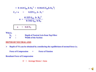
![Now
Force = C = C1 + C2
C = Stress x Area
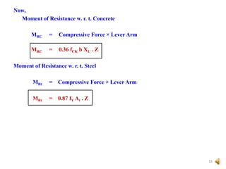
And
MR = Force x Lever Arm
The portion above the Neutral Axis is in Compression and the Strain is
proportional to distance from Neutral Axis (NA) to the Extreme Compression
Fibre i.e. Zero at the NA to a Maximum at the Extreme fibre.
The cross section below the NA is in Tension and hence the Concrete is
assumed to have Cracked.
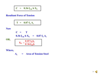
All the Tensile Stresses are supposed to be borne by steel bars and stresses in
all the steel bars are equal.
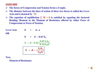
The resultant Tensile Force thus acts at the Centroid of the Reinforcing Bars.
The distance from the Extreme Compression Fibre to the centroid of the
Reinforcing Bars i.e. line of action of Tensile Force is called the Effective Depth
'd'.
Now,
Maximum Compressive Stress in Concrete without Safety Factor
= 0.67 fCK [Assumption 4]
9](https://image.slidesharecdn.com/1-singlyreinforcedsections-beams-audio-220611125802-b21ba99b/85/1-Singly-Reinforced-Sections-Beams-AUDIO-pptx-9-320.jpg)
![MODES OF FAILURE
Balanced Section :-
If the ratio of Steel to Concrete in a beam is such that the maximum strain in
concrete and steel reach simultaneously, a sudden failure would occur with less
alarming deflections.
Such a beam is referred to as a Balanced Reinforced Beam.
Under Reinforced Beam :-
When the amount of steel is kept less than that in the Balanced Section, the NA
moves upwards so as to reduce the area under compression to maintain the
Equilibrium Condition i.e.
Force of Compression is equal to the Force of Tension. [This is because the Force
of tension becomes less than the Force of Compression and hence the Force of
Compression has to be reduced]
In this process the Centre of Gravity of compressive forces also shifts upwards.
Under increasing Bending Moments Steel is strained beyond Yield Point and the
Maximum Strain in concrete remains less than 0.35% i.e. 0.0035.
If the beam is further loaded, the strain in the section increases. Once the steel has
yielded it does not take any additional stresses for the additional strain and the
total force of tension remains constant.
However compressive stresses in concrete increases with the additional strain.
17](https://image.slidesharecdn.com/1-singlyreinforcedsections-beams-audio-220611125802-b21ba99b/85/1-Singly-Reinforced-Sections-Beams-AUDIO-pptx-17-320.jpg)
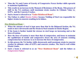
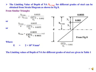
![MAXIMUM DEPTH OF NEUTRAL AXIS
A compression failure in a Over Reinforced Beam is a Brittle Failure.
The Maximum Depth of NA is therefore limited to ensure that the Steel will
reach its Yield Point before Concrete fails in Compression, so that a brittle
Failure is avoided.
Let the Limiting Value of the depth of NA be XU Lim.
When,
XU = XU Lim [ Balanced Section ]
XU < XU Lim [ Under Reinforced Section ]
XU > XU Lim [ Over Reinforced Section ]
19](https://image.slidesharecdn.com/1-singlyreinforcedsections-beams-audio-220611125802-b21ba99b/85/1-Singly-Reinforced-Sections-Beams-AUDIO-pptx-19-320.jpg)
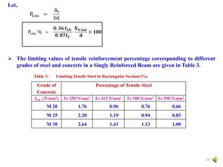
![Minimum and Maximum Tension Reinforcement
Minimum Reinforcement : [ As per Clause 26.5.1.1; pp. 46; of IS 456 - 2000 ]
The minimum area of tension reinforcement should not be less than that given
by the following :
Where,
AS = Minimum Area of Tension Reinforcement
b = Breadth of Beam or breadth of Web of T-Beam
d = Effective depth of Beam
fY = Characteristic Strength of Steel Reinforcement in N/mm2
Maximum Reinforcement :
• The maximum area of tension reinforcement should not exceed 4% of the
Gross Cross-Sectional area of beam to avoid difficulty in placing and
compacting concrete properly in the formwork i.e.
ASM > 0.04 b D
24](https://image.slidesharecdn.com/1-singlyreinforcedsections-beams-audio-220611125802-b21ba99b/85/1-Singly-Reinforced-Sections-Beams-AUDIO-pptx-24-320.jpg)


