Download as PDF, PPTX


![BND TechSource
BND TechSource https://bndtechsource.wixsite.com/home
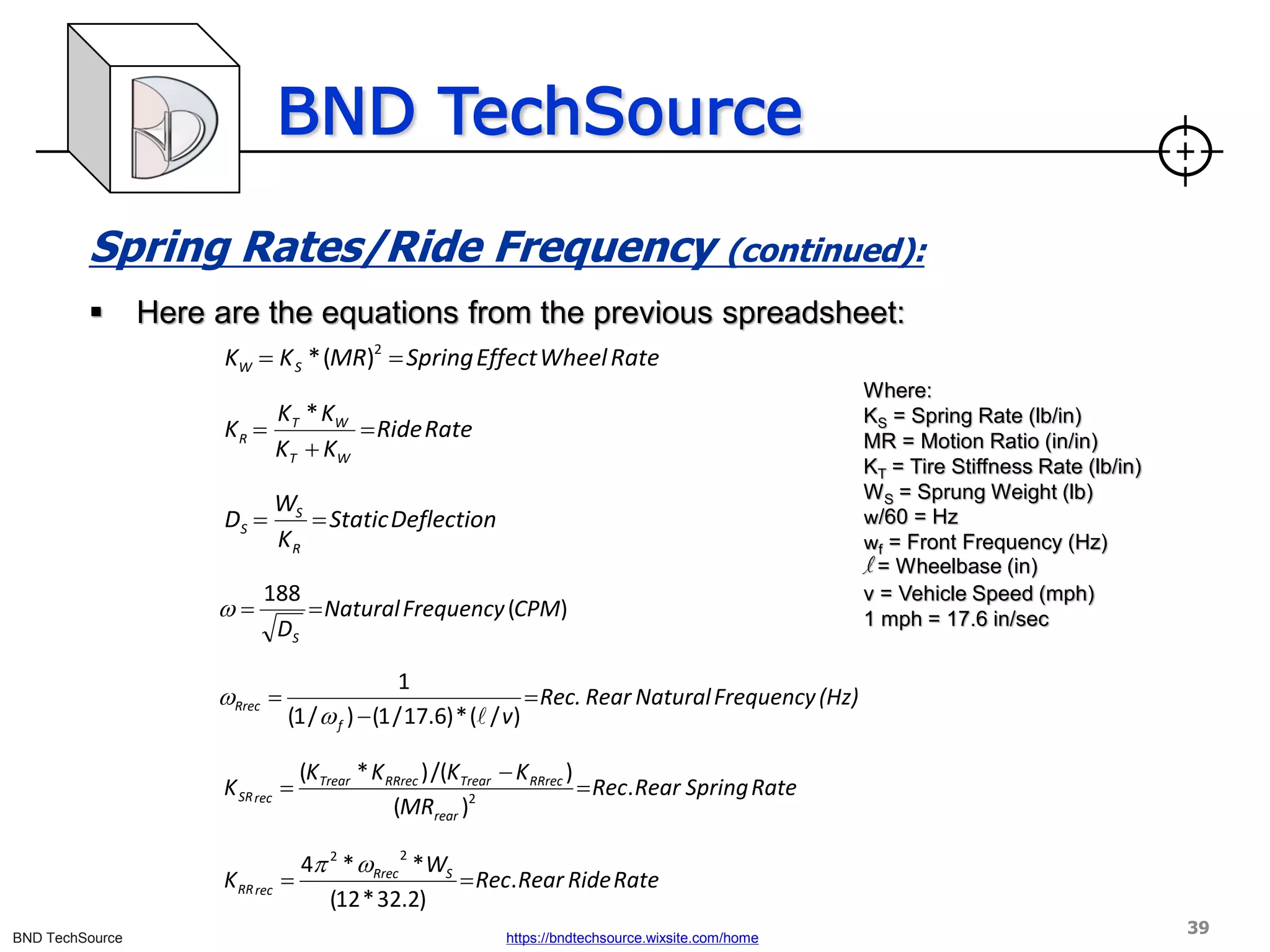
Load Transfer Control Devices (continued):
▪ Anti-roll bars
▪ [Drawing 1] shows how an anti-roll bar (ARB) is twisted when the body rolls in
a turn. This creates forces at the four points where the bar is attached to the
vehicle. The forces are shown in [Drawing 2]. Forces A on the suspension
increase [load] transfer to the outside tire. Forces B on the frame resist body
roll. The effect is a reduction of body roll and an increase in [load] transfer at
the end of the chassis which has the anti-roll bar. Because the total [load]
transfer due to centripetal force is not changed, the opposite end of the
chassis has reduced [load] transfer. [6]
Drawing 2 Drawing 1
Direction of Turn
A A
B
B
25](https://image.slidesharecdn.com/vehicleloadtransferparti2021-210705031759/75/Vehicle-load-transfer-part-I-2021-25-2048.jpg)


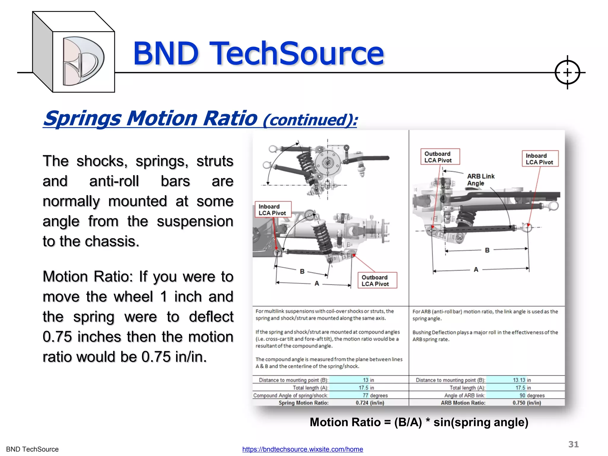
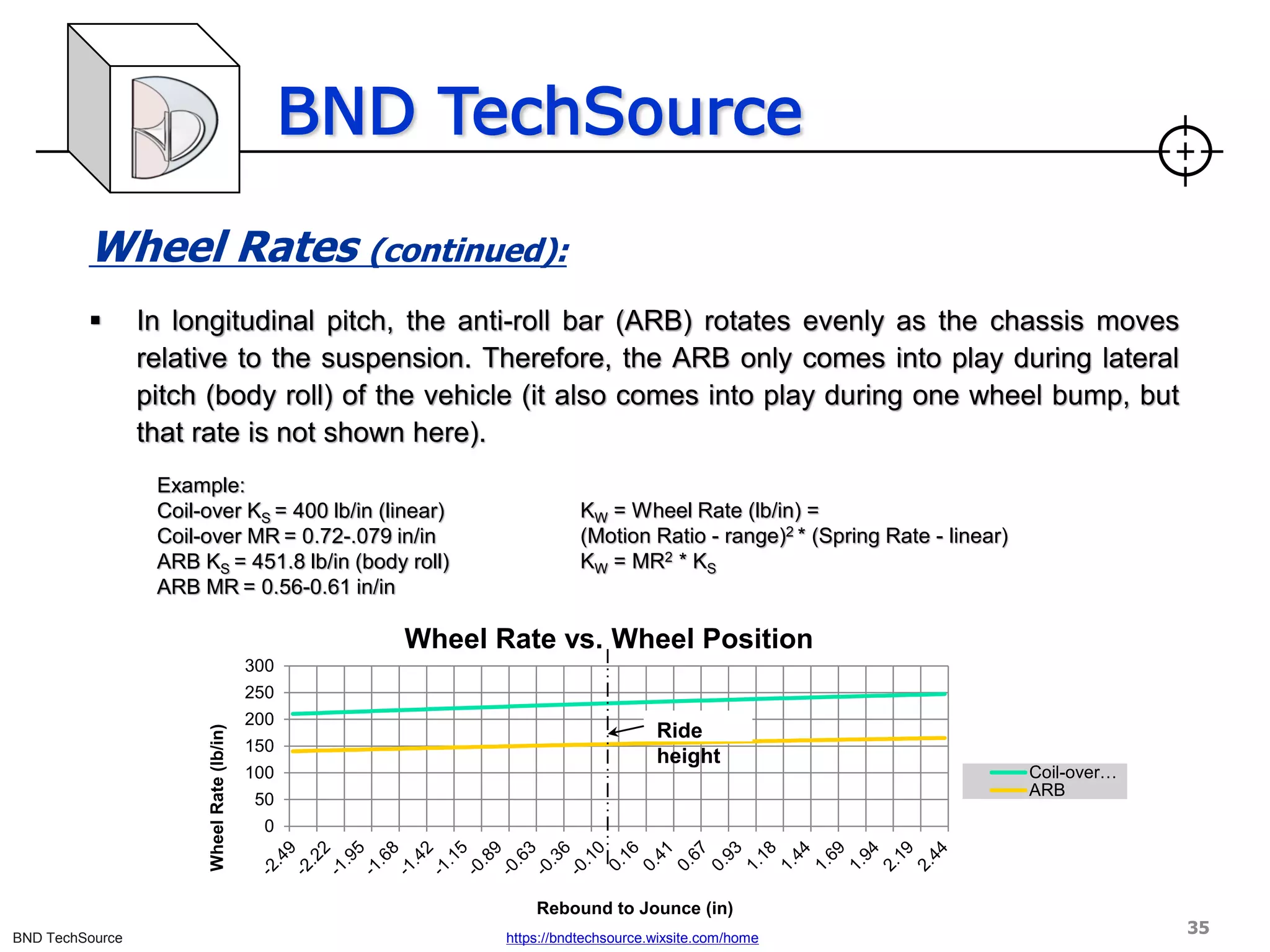
 or 100(MR)2.
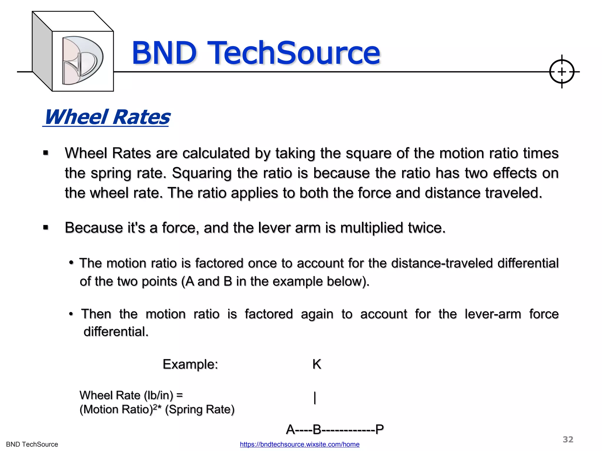
Wheel Rate (lb/in) =
(Motion Ratio)2* (Spring Rate)
33](https://image.slidesharecdn.com/vehicleloadtransferparti2021-210705031759/75/Vehicle-load-transfer-part-I-2021-33-2048.jpg)


![BND TechSource
BND TechSource https://bndtechsource.wixsite.com/home
Ride
▪ “One can start with a desired frequency or with a maximum wheel travel / maximum load. Either
one determines how hard/soft the ride/handling will be. Generally it is desirable to have the
suspension as soft as practical in light of packaging, aerodynamic down load, banked turn
loads, roll stiffness (and roll stiffness distribution). The undamped ride frequency for a given
configuration (the frequency of the body moving up and down on the springs) can be
determined from the graph on page 34, once the static deflection has been estimated. Ride
frequencies for sports cars typically run from 70-90 cycles per minute. Older Indy type cars
without ground effects run 95-120 cpm. With ground effects the frequencies can become very
high-several hundred cpm. Passenger cars, by comparison, can be very ---30-50 cpm.”[5]
▪ Wheel travels for several classes of vehicles are typically:
▪ Off-road trucks ±12 in.
▪ Passenger cars ±4 in.
▪ Sports cars and small formula cars ±2 to ±4 in.
▪ Indy type cars (ground effects) ±0.5 in. (or less)
42](https://image.slidesharecdn.com/vehicleloadtransferparti2021-210705031759/75/Vehicle-load-transfer-part-I-2021-42-2048.jpg)
![BND TechSource
BND TechSource https://bndtechsource.wixsite.com/home
Roll
▪ “The stiffness in roll is conveniently expressed in normalized form as degrees of roll per unit
lateral acceleration (deg./g). This is called the roll gradient.”[5]
43](https://image.slidesharecdn.com/vehicleloadtransferparti2021-210705031759/75/Vehicle-load-transfer-part-I-2021-43-2048.jpg)


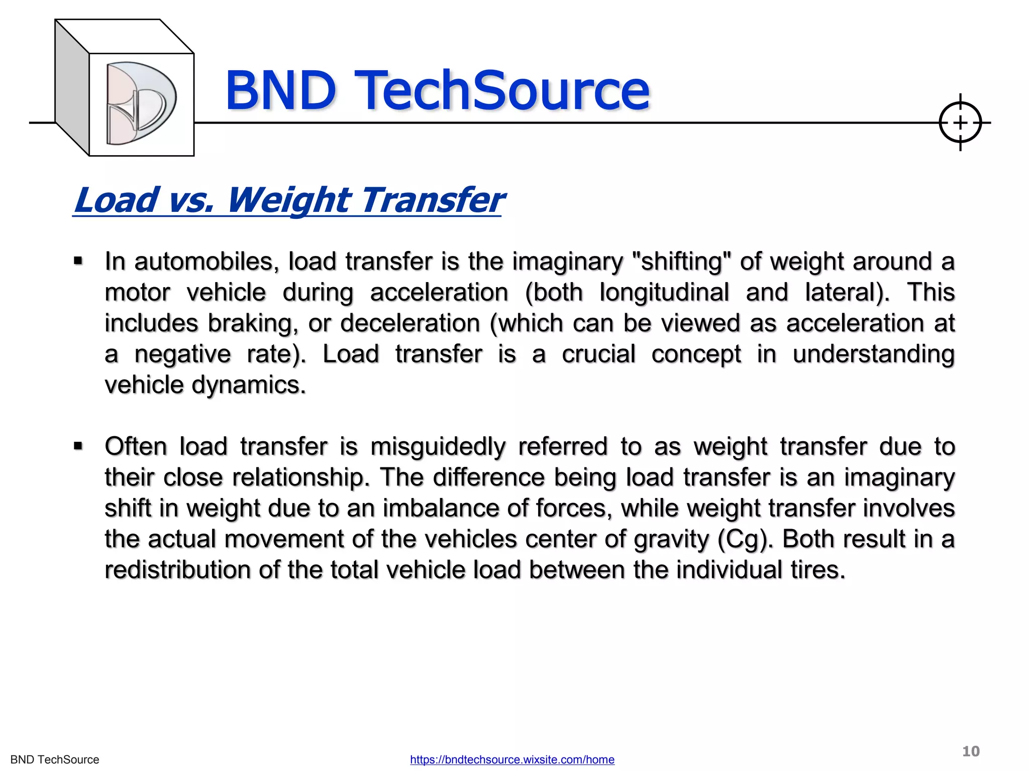
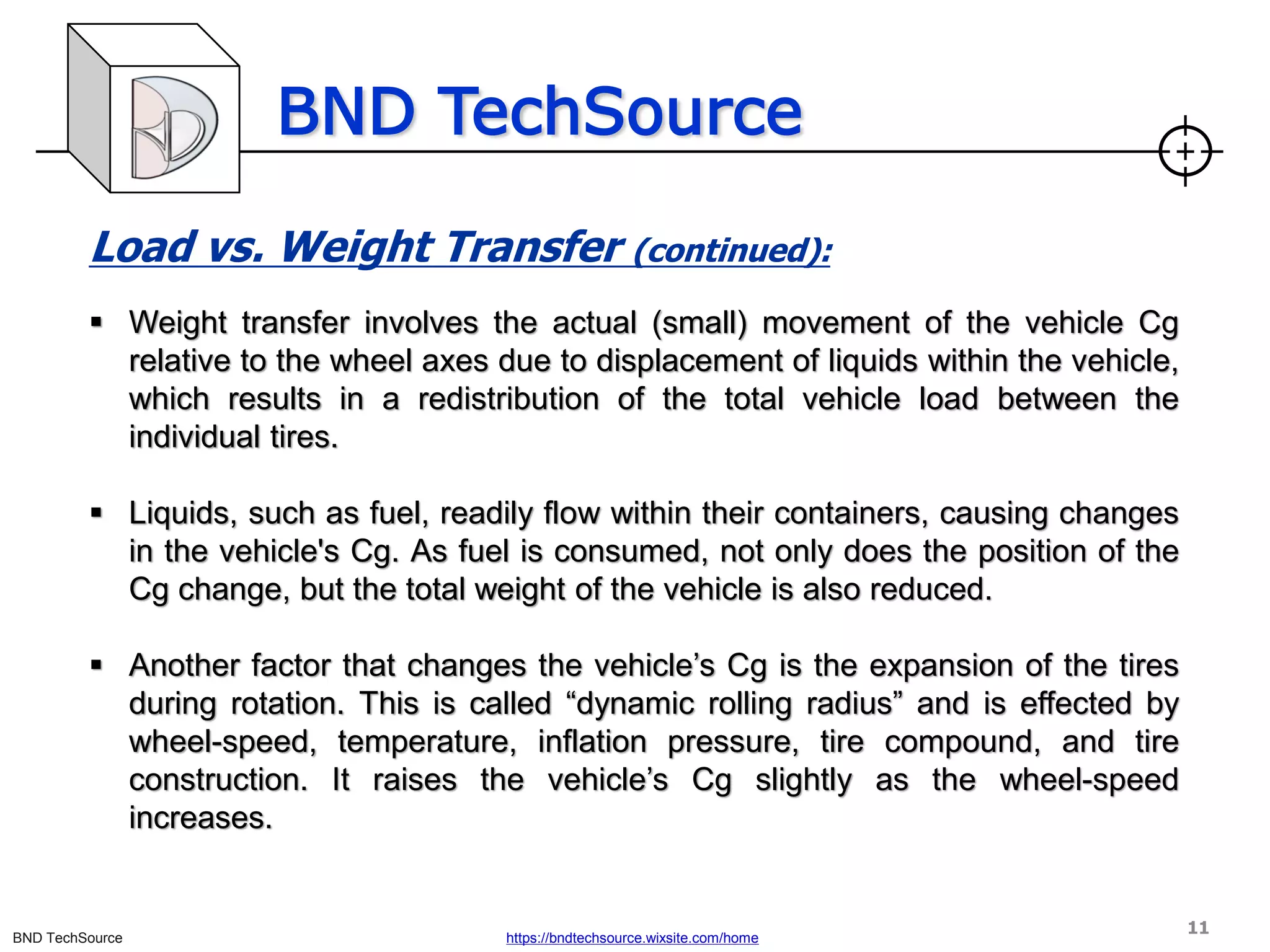
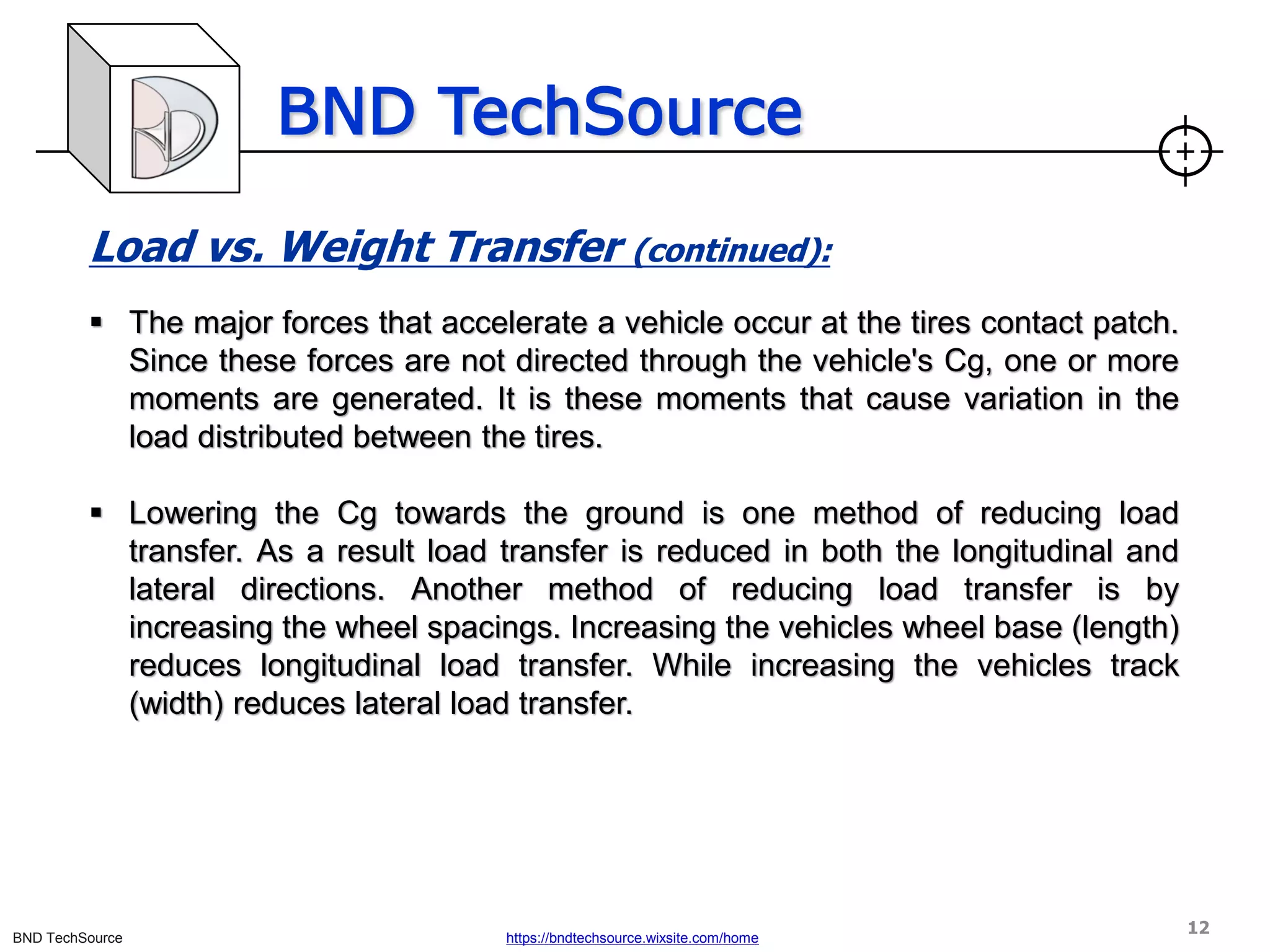
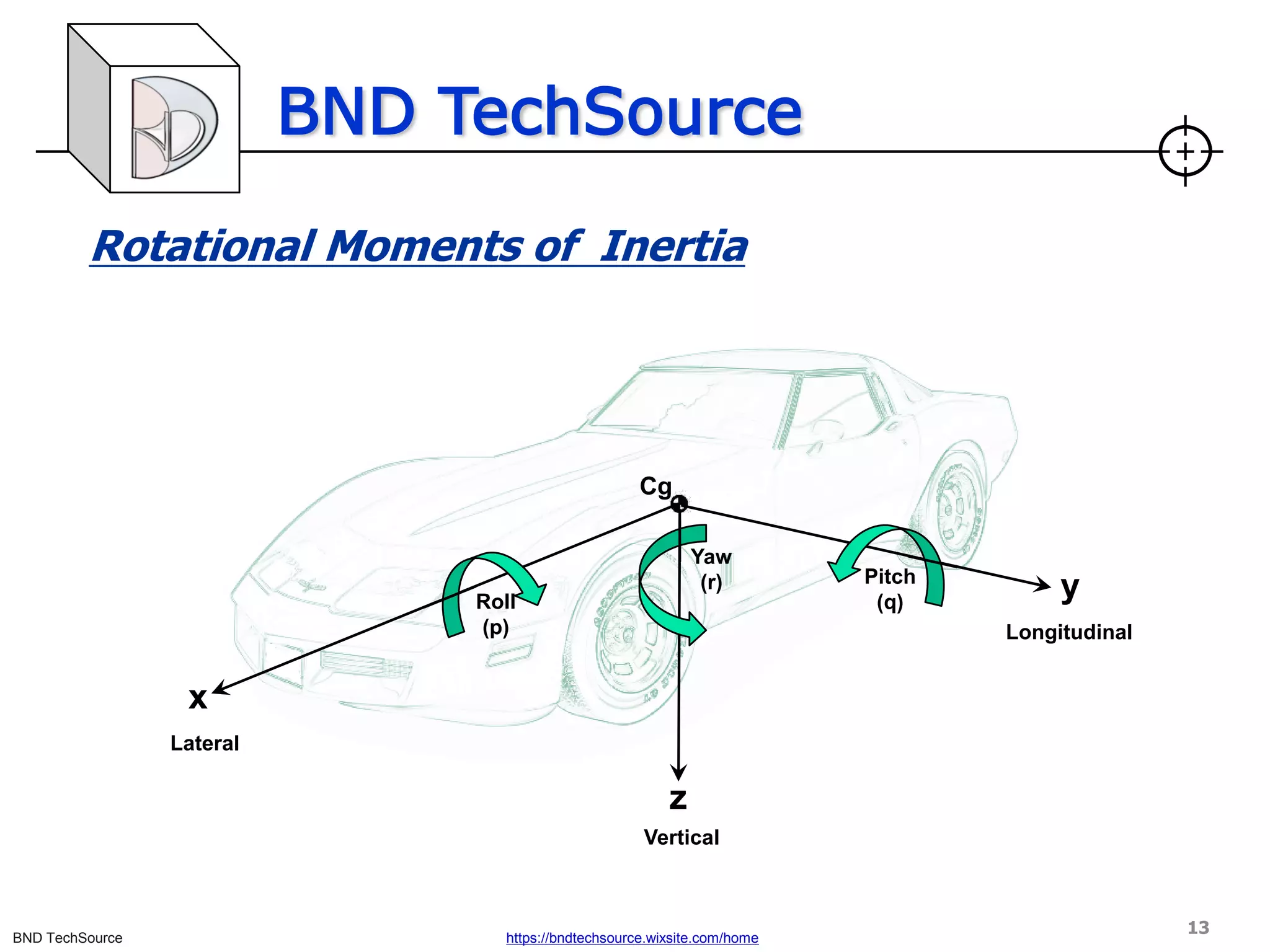
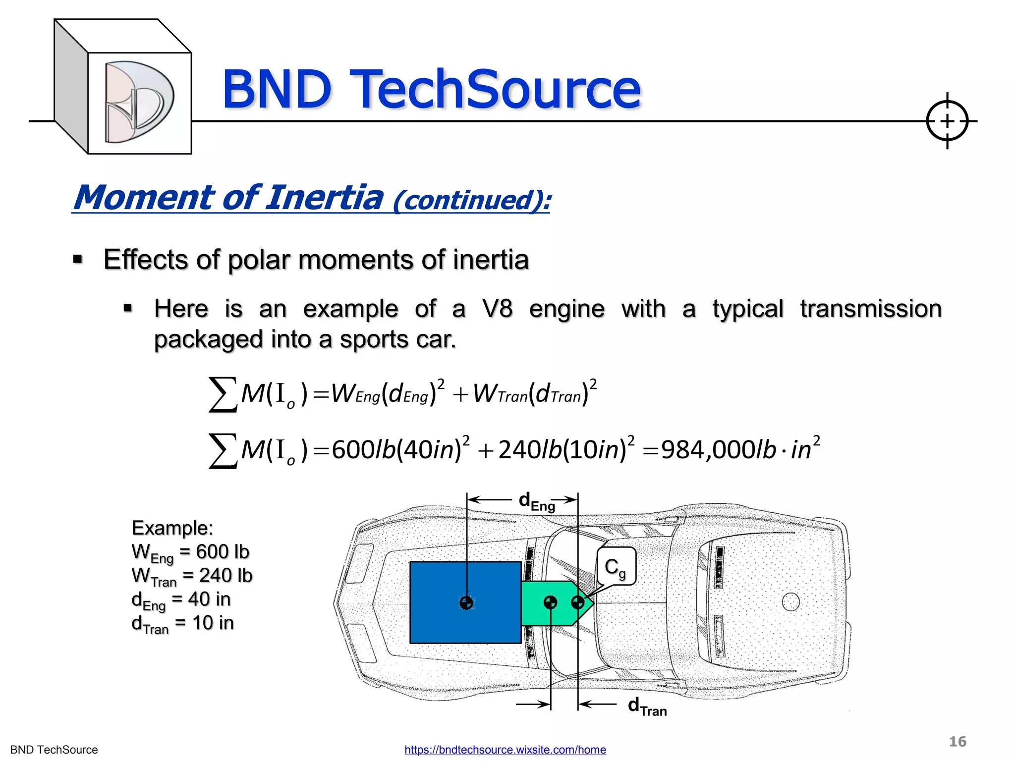
This document discusses factors that influence vehicle dynamics and load transfer. It defines load transfer as the imaginary shifting of weight in a vehicle during acceleration or braking, versus actual weight transfer which involves movement of the vehicle's center of gravity. Key factors discussed include vehicle configuration, suspension geometry, springs, dampers, anti-roll bars, and how they control and influence load transfer both longitudinally and laterally. The document provides equations for load transfer and explores concepts like polar moment of inertia and its effects on vehicle handling.


