SlideShare a Scribd company logo
1 of 58
Download to read offline
SECTION 15 – FLEXIBLE POWER-TRANSMITTING ELEMENTS
757
LEATHER BELTS
DESIGN PROBLEMS
841. A belt drive is to be designed for 321 =FF , while transmitting 60 hp at 2700
rpm of the driver 1D ; 85.1≈wm ; use a medium double belt, cemented joint, a
squirrel-cage, compensator-motor drive with mildly jerking loads; center distance
is expected to be about twice the diameter of larger pulley. (a) Choose suitable
iron-pulley sizes and determine the belt width for a maximum permissible
psis 300= . (b) How does this width compare with that obtained by the ALBA
procedure? (c) Compute the maximum stress in the straight port of the ALBA
belt. (d) If the belt in (a) stretches until the tight tension lbF 5251 = ., what is
21 FF ?
Solution:
(a) Table 17.1, Medium Double Ply,
Select inD 71 = . min.
int
64
20
=
( )( ) fpm
nD
vm 4948
12
27007
12
11
===
ππ
fpmfpmfpm 600049484000 <<
( )
000,33
21 mvFF
hp
−
=
( )( )
000,33
4948
60 21 FF −
=
lbFF 40021 =−
21 3FF =
lbFF 4003 22 =−
lbF 2002 =
( ) lbFF 60020033 21 ===
sbtF =1
η300=ds
For cemented joint, 0.1=η
psisd 300=
( )( ) 





==
64
20
3006001 bF
inb 4.6=
say inb 5.6=
SECTION 15 – FLEXIBLE POWER-TRANSMITTING ELEMENTS
758
(b) ALBA Procedure
( )( )( )L21
1.17., ffpm CCCbCTableinhphp =
Table 17.1, fpmvm 4948=
Medium Double Ply
448.12=inhp
Table 17.2
Squirrel cage, compensator, starting
67.0=mC
Pulley Size, inD 71 =
6.0=pC
Jerky loads, 83.0=fC
( )( )( )( )( )83.06.067.0448.1260 bhp ==
inb 5.14=
say inb 15=
(c)
( )( )
psi
bt
F
s 128
64
20
151
6001
=






==
η
(d) ( ) ( )2
1
2
1
2
1
2
2
1
1
2
1
2006002 +=+= FFFo
lbFo 2.373=
lbF 5251 =
( ) ( ) 2
1
2
2
1
2
1
5252.3732 F+=
lbF 2472 =
1255.2
247
525
2
1
==
F
F
842. A 20-hp, 1750 rpm, slip-ring motor is to drive a ventilating fan at 330 rpm. The
horizontal center distance must be about 8 to 9 ft. for clearance, and operation is
continuous, 24 hr./day. (a) What driving-pulley size is needed for a speed
recommended as about optimum in the Text? (b) Decide upon a pulley size (iron
or steel) and belt thickness, and determine the belt width by the ALBA tables. (c)
Compute the stress from the general belt equation assuming that the applicable
coefficient of friction is that suggested by the Text. (d) Suppose the belt is
installed with an initial tension inlbFo 70= . (§17.10), compute 21 FF and the
stress on the tight side if the approximate relationship of the operating tensions
and the initial tensions is 2
1
2
1
2
2
1
1 2 oFFF =+ .
SECTION 15 – FLEXIBLE POWER-TRANSMITTING ELEMENTS
759
Solution:
fpmtovm 45004000=
assume fpmvm 4250=
12
11nD
vm
π
=
( )
12
1750
4250 1Dπ
=
inD 26.91 =
say inD 101 =
(b) Using Heavy Double Ply Belt, int
64
23
=
Minimum pulley diameter for fpmvm 4250≈ , inD 101 =
Use inD 101 =
( )( ) fpm
nD
vm 4581
12
175010
12
11
===
ππ
ALBA Tables
( )( )( )L21
1.17., ffpm CCCbCTableinhphp =
8.13=inhp
Slip ring motor, 4.0=mC
Pulley Size, inD 101 =
7.0=pC
Table 17.7, 24 hr/day, continuous
8.1=sfN
Assume 74.0=fC
( )( ) ( )( )( )( )( )74.07.04.08.13208.1 bhp ==
inb 59.12=
use inb 13=
(c) General belt equation





 −






−=− θ
θ
ρ
f
f
s
e
ev
sbtFF
1
2.32
12 2
21
fpsvs 35.76
60
4581
==
..035.0 inculb=ρ for leather
int
64
23
=
inb 13=
SECTION 15 – FLEXIBLE POWER-TRANSMITTING ELEMENTS
760
( )( ) lbFF 260
4581
208.1000,33
21 ==−
3.0=f on iron or steel
C
DD 12 −
±≈ πθ
ftC 9~8= use 8.5 ft
( ) inD 5310
330
1750
2 =





=
( )
rad72.2
125.8
1053
=
−
−= πθ
( )( ) 816.072.23.0 ==θf
5578.0
11
816.0
816.0
=
−
=
−
e
e
e
e
f
f
θ
θ
( ) ( )( ) ( )5578.0
2.32
35.76035.012
64
23
13260
2
21 





−





==− sFF
psis 176=
(d) 2
1
2
1
2
2
1
1 2 oFFF =+
( )( ) lbininlbFo 9101370 ==
lbFF 26021 =−
lbFF 26012 −=
( ) ( ) 33.609102260 2
1
2
1
1
2
1
1 ==−+ FF
lbF 10451 =
lbF 78526010452 =−=
( )
psi
bt
F
s 224
64
23
13
10451
=






==
331.1
785
1045
2
1
==
F
F
843. A 100-hp squirrel-cage, line-starting electric motor is used to drive a Freon
reciprocating compressor and turns at 1140 rpm; for the cast-iron motor pulley,
inD 161 = ; inD 532 = , a flywheel; cemented joints;l ftC 8= . (a) Choose an
appropriate belt thickness and determine the belt width by the ALBA tables. (b)
Using the design stress of §17.6, compute the coefficient of friction that would be
needed. Is this value satisfactory? (c) Suppose that in the beginning, the initial
tension was set so that the operating 221 =FF . Compute the maximum stress in
a straight part. (d) The approximate relation of the operating tensions and the
SECTION 15 – FLEXIBLE POWER-TRANSMITTING ELEMENTS
761
initial tension oF is 2
1
2
1
2
2
1
1 2 oFFF =+ . For the condition in (c), compute oF . Is it
reasonable compared to Taylor’s recommendation?
Solution:
(a) Table 17.1
( )( ) fpm
nD
vm 4775
12
114016
12
11
===
ππ
Use heavy double-ply belt
int
64
23
=
1.14=inhp
( )( )( )L21
1.17., ffpm CCCbCTableinhphp =
line starting electric motor , 5.0=mC
Table 17.7, squirrel-cage, electric motor, line starting, reciprocating compressor
4.1=sfN
inD 161 = , 8.0=pC
assume, 74.0=fC
( )( ) hphp 1401004.1 ==
( )( )( )( )( )74.08.05.01.14140 bhp ==
inb 5.33=
use inb 34=
(b) §17.6, η400=ds
00.1=η for cemented joint.
psisd 400=





 −






−=− θ
θ
ρ
f
f
s
e
ev
sbtFF
1
2.32
12 2
21
fpsvs 6.79
60
4775
==
..035.0 inculb=ρ for leather
int
64
23
=
inb 34=
( )( ) lbFF 968
4775
1004.1000,33
21 ==−
( ) ( )( )





 −






−





==− θ
θ
f
f
e
e
FF
1
2.32
6.79035.012
400
64
23
34968
2
21
SECTION 15 – FLEXIBLE POWER-TRANSMITTING ELEMENTS
762
2496.0
1
=
−
θ
θ
f
f
e
e
28715.0=θf
C
DD 12 −
±≈ πθ
ftC 8=
( )
rad7562.2
128
1653
=
−
−= πθ
( ) 28715.07562.2 =f
3.01042.0 <=f
Therefore satisfactory.
(c) lbFF 96821 =−
21 2FF =
lbFF 9682 22 =−
( ) lbFF 193696822 21 ===
( )
psi
bt
F
s 159
64
23
34
19361
=






==
(d) lbF 19361 = , lbF 9682 =
2
1
2
2
1
1
2
1
2 FFFo +=
( ) ( )2
1
2
1
2
1
96819362 +=oF
lbFo 1411=
inlbFo 5.41
34
1411
== of width is less than Taylor’s recommendation and is reasonable.
844. A 50-hp compensator-started motor running at 865 rpm drives a reciprocating
compressor for a 40-ton refrigerating plant, flat leather belt, cemented joints. The
diameter of the fiber driving pulley is 13 in., inD 702 = ., a cast-iron flywheel;
.11.6 inftC = Because of space limitations, the belt is nearly vertical; the
surroundings are quite moist. (a) Choose a belt thickness and determine the width
by the ALBA tables. (b) Using recommendations in the Text, compute s from
the general belt equation. (c) With this value of s , compute 1F and 21 FF . (d)
Approximately, 2
1
2
1
2
2
1
1 2 oFFF =+ , where oF is the initial tension. For the
condition in (c), what should be the initial tension? Compare with Taylor, §17.10.
(e) Compute the belt length. (f) The data are from an actual drive. Do you have
any recommendations for redesign on a more economical basis?
SECTION 15 – FLEXIBLE POWER-TRANSMITTING ELEMENTS
763
Solution:
(a)
( )( ) fpm
nD
vm 2944
12
86513
12
11
===
ππ
Table 17.1, use Heavy Double Ply,
inD 9min = for fpmvm 2944=
belts less than 8 in wide
int
64
23
=
( )( )( )L21
1.17., ffpm CCCbCTableinhphp =
86.9=inhp
Table 17.2
67.0=mC
8.0=pC
( )( ) 61420830740 ... ==fC
Table 17.7, electric motor, compensator-started (squirrel cage) and reciprocating
compressor
4.1=sfN
( )( ) hphp 70504.1 ==
( )( )( )( )( )614208067086970 .... bhp ==
inb 621.=
use inb 25=
(b) General Belt Equation





 −






−=− θ
θ
ρ
f
f
s
e
ev
sbtFF
1
2.32
12 2
21
inb 25=
int
64
23
=
..035.0 inculb=ρ for leather
fpsvs 1.49
60
2944
==
Leather on iron, 3.0=f
C
DD 12 −
−= πθ
( )
rad4552
11126
1370
.=
+
−
−=πθ
( )( ) 73650455230 ... ==θf
SECTION 15 – FLEXIBLE POWER-TRANSMITTING ELEMENTS
764
52120
11
73650
73650
..
.
=
−
=
−
e
e
e
e
f
f
θ
θ
( )( ) lbFF 785
2944
504.1000,33
21 ==−
( )
( )( )
( )52120
232
149035012
64
23
25785
2
21 .
.
..






−





==− sFF
psis 199=
Cemented joint, 0.1=η
psis 199=
(c) ( )( ) lbsbtF 1788
64
23
251991 =





==
lbF 100378517882 =−=
7831
1003
1788
2
1
.==
F
F
(d) 2
1
2
2
1
1
2
1
2 FFFo +=
( ) ( )2
1
2
1
2
1
100317882 +=oF
lbFo 1367=
inlbFo 754
25
1367
.==
Approximately less than Taylor’s recommendation ( = 70 lb/in.)
(e) ( ) ( )
C
DD
DDCL
4
57.12
2
12
12
−
+++≈
( )( )[ ] ( ) ( )
( )( )[ ]
inL 306
111264
1370
1370571111262
2
=
+
−
++++= .
(f) More economical basis
12
11nD
vm
π
=
( )
12
865
4500 1Dπ
=
inD 87.191 =
use inD 201 =
SECTION 15 – FLEXIBLE POWER-TRANSMITTING ELEMENTS
765
CHECK PROBLEMS
846. An exhaust fan in a wood shop is driven by a belt from a squirrel-cage motor that
runs at 880 rpm, compensator started. A medium double leather belt, 10 in. wide
is used; inC 54= .; inD 141 = . (motor), inD 542 = ., both iron. (a) What
horsepower, by ALBA tables, may this belt transmit? (b) For this power,
compute the stress from the general belt equation. (c) For this stress, what is
21 FF ? (d) If the belt has stretched until psis 200= on the tight side, what is
21 FF ? (e) Compute the belt length.
Solution:
(a) For medium double leather belt
int
64
20
=
( )( ) fpm CCCbinhphp =
Table 17.1 and 17.2
67.0=mC
8.0=pC
74.0=fC
inb 10=
( )( ) fpm
nD
vm 3225
12
88014
12
11
===
ππ
6625.6=inhp
( )( )( )( )( ) hphp 43.2674.08.067.0106625.6 ==
(b) 




 −






−=− θ
θ
ρ
f
f
s
e
ev
sbtFF
1
2.32
12 2
21
inb 10=
int
64
20
=
..035.0 inculb=ρ
fpsvs 75.53
60
3225
==
C
DD 12 −
−= πθ
rad4.2
54
1454
=
−
−= πθ
Leather on iron 3.0=f
( )( ) 72.04.23.0 ==θf
SECTION 15 – FLEXIBLE POWER-TRANSMITTING ELEMENTS
766
51325.0
11
72.0
72.0
=
−
=
−
e
e
e
e
f
f
θ
θ
( ) lbFF 270
3225
43.26000,33
21 ==−
( ) ( )( ) ( )51325.0
2.32
75.53035.012
64
20
10270
2
21 





−





==− sFF
psis 206=
(c) ( )( ) lbsbtF 644
64
20
102061 =





==
lbF 3742706442 =−=
72.1
374
644
2
1
==
F
F
(d) psis 200=
( )( ) lbsbtF 625
64
20
102001 =





==
lbF 3552706252 =−=
76.1
355
625
2
1
==
F
F
(e) ( ) ( )
C
DD
DDCL
4
57.12
2
12
12
−
+++≈
( ) ( ) ( )
( )
inL 222
544
1454
145457.1542
2
=
−
+++=
847. A motor is driving a centrifugal compressor through a 6-in. heavy, single-ply
leather belt in a dusty location. The 8-in motor pulley turns 1750 rpm;
inD 122 = . (compressor shaft); ftC 5= . The belt has been designed for a net
belt pull of inlbFF 4021 =− of width and 321 =FF . Compute (a) the
horsepower, (b) the stress in tight side. (c) For this stress, what needed value of
f is indicated by the general belt equation? (d) Considering the original
data,what horsepower is obtained from the ALBA tables? Any remarks?
Solution:
(a)
( )( ) fpm
nD
vm 3665
12
17508
12
11
===
ππ
inb 6=
( )( ) lbFF 24064021 ==−
SECTION 15 – FLEXIBLE POWER-TRANSMITTING ELEMENTS
767
( ) ( )( ) hp
vFF
hp m
65.26
000,33
3665240
000,33
21
==
−
=
(b) 21 3FF =
lbFF 2403 22 =−
lbF 1202 =
lbF 3601 =
bt
F
s 1
=
For heavy single-ply leather belt
int
64
13
=
( )
psis 295
64
13
6
360
=






=
(c) 




 −






−=− θ
θ
ρ
f
f
s
e
ev
sbtFF
1
2.32
12 2
21
..035.0 inculb=ρ
fpsvs 1.61
60
3665
==
lbFF 24021 =−
( ) ( )( )





 −






−





==− θ
θ
f
f
e
e
FF
1
2.32
1.61035.012
295
64
13
6240
2
21
7995.0
1
=
−
θ
θ
f
f
e
e
C
DD 12 −
−= πθ
( )
rad075.3
125
812
=
−
−= πθ
9875.4=θf
e
607.1=θf
( ) 607.1075.3 =f
5226.0=f
(d) ALBA Tables (Table 17.1 and 17.2)
( )( ) fpm CCCbinhphp =
fpmvm 3665=
965.6=inhp
SECTION 15 – FLEXIBLE POWER-TRANSMITTING ELEMENTS
768
inb 10=
0.1=mC (assumed)
6.0=pC
74.0=fC
( )( )( )( )( ) hphphp 65.266.1874.06.00.16965.6 <==
848. A 10-in. medium double leather belt, cemented joints, transmits 60 hp from a 9-
in. paper pulley to a 15-in. pulley on a mine fab; dusty conditions. The
compensator-started motor turns 1750 rpm; inC 42= . This is an actual
installation. (a) Determine the horsepower from the ALBA tables. (b) Using the
general equation, determine the horsepower for this belt. (c) Estimate the service
factor from Table 17.7 and apply it to the answer in (b). Does this result in better
or worse agreement of (a) and (b)? What is your opinion as to the life of the belt?
Solution:
( )( ) fpm
nD
vm 4123
12
17509
12
11
===
ππ
(a) ( )( ) fpm CCCbinhphp =
Table 17.1 and 17.2
Medium double leather belt
int
64
20
=
fpmvm 4123=
15.11=inhp
67.0=mC
7.0=pC
74.0=fC
inb 10=
( )( )( )( )( ) hphp 7.3874.07.067.01015.11 ==
(b) 




 −






−=− θ
θ
ρ
f
f
s
e
ev
sbtFF
1
2.32
12 2
21
inb 10=
..035.0 inculb=ρ
η400=s
0.1=η cemented joint
psis 400=
C
DD 12 −
−= πθ
SECTION 15 – FLEXIBLE POWER-TRANSMITTING ELEMENTS
769
rad9987.2
42
915
=
−
−= πθ
Leather on paper pulleys, 5.0=f
( )( ) 5.19987.25.0 ==θf
77687.0
1
=
−
θ
θ
f
f
e
e
fpsvs 72.68
60
4123
==
( ) ( )( ) ( ) lbFF 82277687.0
2.32
72.68035.012
400
64
20
10
2
21 =





−





=−
( ) ( )( ) hp
vFF
hp m
7.102
000,33
4123822
000,33
21
==
−
=
(c) Table 17.7
6.1=sfN
hphphp 7.1022.64
6.1
7.102
<==
Therefore, better agreement
Life of belt, not continuous, hphp 7.3860 > .
MISCELLANEOUS
849. Let the coefficient of friction be constant. Find the speed at which a leather belt
may transmit maximum power if the stress in the belt is (a) 400 psi, (b) 320 psi.
(c) How do these speeds compare with those mentioned in §17.9, Text? (d)
Would the corresponding speeds for a rubber belt be larger or smaller? (HINT:
Try the first derivative of the power with respect to velocity.)
Solution:





 −






−=− θ
θ
ρ
f
f
s
e
ev
sbtFF
1
2.32
12 2
21
( )
000,33
21 mvFF
hp
−
=
( )
000,33
60 21 svFF
hp
−
=





 −






−= θ
θ
ρ
f
f
ss
e
ev
s
btv
hp
1
2.32
12
000,33
60 2
s
s
f
f
v
v
s
e
ebt
hp 





−




 −
=
2.32
121
000,33
60 2
ρ
θ
θ
SECTION 15 – FLEXIBLE POWER-TRANSMITTING ELEMENTS
770
( )
( )
0
2.32
24
2.32
121
000,33
60 22
=





−





−




 −
= ss
f
f
s
vv
s
e
ebt
vd
hpd ρρ
θ
θ
2.32
36 2
sv
s
ρ
=
..035.0 inculb=ρ
(a) psis 400=
( )
2.32
035.036
400
2
sv
=
fpsvs 105.101=
fpmvm 6066=
(b) psis 320=
( )
2.32
035.036
320
2
sv
=
fpsvs 431.90=
fpmvm 5426=
(c) Larger than those mentioned in §17.9 (4000 – 4500 fpm)
(d) Rubber belt, ..045.0 inculb=ρ
(a) psis 400=
( )
2.32
045.036
400
2
sv
=
fpsvs 166.89=
fpmfpmvm 60665350 <=
Therefore, speeds for a rubber belt is smaller.
850. A 40-in. pulley transmits power to a 20-in. pulley by means of a medium double
leather belt, 20 in. wide; ftC 14= , let 3.0=f . (a) What is the speed of the 40-in
pulley in order to stress the belt to 300 psi at zero power? (b) What maximum
horsepower can be transmitted if the indicated stress in the belt is 300 psi? What
is the speed of the belt when this power is transmitted? (See HINT in 849).
Solution:





 −






−=− θ
θ
ρ
f
f
s
e
ev
sbtFF
1
2.32
12 2
21
SECTION 15 – FLEXIBLE POWER-TRANSMITTING ELEMENTS
771
( )
000,33
60 21 svFF
hp
−
=
s
s
f
f
v
v
s
e
ebt
hp 





−




 −
=
2.32
121
000,33
60 2
ρ
θ
θ
( )
( )
0
2.32
24
2.32
121
000,33
60 22
=





−





−




 −
= ss
f
f
s
vv
s
e
ebt
vd
hpd ρρ
θ
θ
2.32
36 2
sv
s
ρ
= for maximum power
(a) At zero power:
2.32
12 2
sv
s
ρ
=
psis 300=
..035.0 inculb=ρ
( )
2.32
035.012
300
2
sv
=
fpsvs 6575.151=
fpmvm 9100=
Speed, 40 in pulley,
( )
( )
rpm
D
v
n m
869
40
91001212
2
2 ===
ππ
(b) Maximum power
2.32
36 2
sv
s
ρ
=
( )
2.32
035.036
300
2
sv
=
fpsvs 5595.87=
fpmvm 5254=
s
s
f
f
v
v
s
e
ebt
hp 





−




 −
=
2.32
121
000,33
60 2
ρ
θ
θ
int
64
20
=
inb 20=
C
DD 12 −
−= πθ
( )
rad0225.3
1214
2040
=
−
−= πθ
3.0=f
SECTION 15 – FLEXIBLE POWER-TRANSMITTING ELEMENTS
772
( )( ) 90675.00225.33.0 ==θf
5962.0
1
=
−
θ
θ
f
f
e
e
( )
( ) ( )( ) ( ) 64.1185595.87
2.32
5595.87035.012
3005962.0
000,33
64
20
2060 2
=





−






=hp
fpmvm 5254=
AUTOMATIC TENSION DEVICES
851. An ammonia compressor is driven by a 100-hp synchronous motor that turns
1200 rpm; 12-in. paper motor pulley; 78-in. compressor pulley, cast-iron;
inC 84= . A tension pulley is placed so that the angle of contact on the motor
pulley is 193o
and on the compressor pulley, 240o
. A 12-in. medium double
leather belt with a cemented joint is used. (a) What will be the tension in the
tight side of the belt if the stress is 375 psi? (b) What will be the tension in the
slack side? (c) What coefficient of friction is required on each pulley as indicated
by the general equation? (d) What force must be exerted on the tension pulley to
hold the belt tight, and what size do you recommend?
Solution:
(a) sbtF =1
inb 12=
int
64
20
=
( )( ) 





=
64
20
123751F
(b)
mv
hp
FF
000,33
21 =−
( )( ) fpm
nD
vm 3770
12
120012
12
11
===
ππ
Table 17.7, 2.1=sfN
( )( ) lbFF 1050
3770
1002.1000,33
21 ==−
lbFF 35610501406105012 =−=−=
(c) 




 −






−=− θ
θ
ρ
f
f
s
e
ev
sbtFF
1
2.32
12 2
21
fpsvs 83.62
60
3770
==
SECTION 15 – FLEXIBLE POWER-TRANSMITTING ELEMENTS
773
..035.0 inculb=ρ
( ) ( )( )





 −




−





= θ
θ
f
f
e
e 1
2.32
83.62035.012
375
64
20
121050
8655.0
1
=
−
θ
θ
f
f
e
e
006.2=θf
Motor pulley
rad3685.3
180
193193 =





==
π
θ o
( ) 006.23685.3 =f
5955.0=f
Compressor Pulley
rad1888.4
180
2402403 =





==
π
θ o
( ) 006.21888.4 =f
4789.0=f
(d) Force:
Without tension pulley
rad
C
DD
356.2
84
127812
1 =
−
−=
−
−= ππθ
rad
C
DD
9273.3
84
127812
2 =
−
+=
−
+= ππθ
SECTION 15 – FLEXIBLE POWER-TRANSMITTING ELEMENTS
774
o
5.356197.0
2
356.2
356.23685.3
2
1
111 ==
−
−−=
−
−−′= rad
πθπ
θθα
o
5.376544.09273.31888.4
2
9273.3
2
22
2
2 ==−+
−
=−′+
−
= rad
π
θθ
πθ
α
( ) ( ) lbFQ 16725.37sin5.35sin1406sinsin 211 =+=+= αα of force exerted
Size of pulley; For medium double leather belt,
fpmvm 3770= , width = inin 812 >
inD 826 =+=
SECTION 15 – FLEXIBLE POWER-TRANSMITTING ELEMENTS
775
852. A 40-hp motor, weighing 1915 lb., runs at 685 rpm and is mounted on a pivoted
base. In Fig. 17.11, Text, ine 10= ., inh
16
3
19= . The center of the 11 ½-in.
motor pulley is 11 ½ in. lower than the center of the 60-in. driven pulley;
inC 48= . (a) With the aid of a graphical layout, find the tensions in the belt for
maximum output of the motor if it is compensator started. What should be the
width of the medium double leather belt if psis 300= ? (c) What coefficient of
friction is indicated by the general belt equation? (Data courtesy of Rockwood
Mfg. Co.)
Solution:
(a)
lbR 1915=
Graphically
inb 26≈
ina 9≈
[ ]∑ = 0BM
bFaFeR 21 +=
( )( ) ( )( ) ( )( )269191510 21 FF +=
150,19269 21 =+ FF
For compensator started
( ) ( ) hphpratedhp 56404.14.1 ===
mv
hp
FF
000,33
21 =−
SECTION 15 – FLEXIBLE POWER-TRANSMITTING ELEMENTS
776
( )( ) fpm
nD
vm 2062
12
6855.11
12
11
===
ππ
( ) lbFF 896
2062
56000,33
21 ==−
89612 −= FF
Substituting
( ) 150,19896269 11 =−+ FF
lbF 12131 =
lbF 31789612132 =−=
For medium leather belt, int
64
20
=
sbtF =1
( )( ) 





=
64
20
3001213 b
inb 13=
(c) 




 −






−=− θ
θ
ρ
f
f
s
e
ev
sbtFF
1
2.32
12 2
21
fpsvs 37.34
60
2062
==
..035.0 inculb=ρ
( ) ( )( )





 −




−





= θ
θ
f
f
e
e 1
2.32
37.34035.012
300
64
20
13896
775.0
1
=
−
θ
θ
f
f
e
e
492.1=θf
rad
C
DD
1312.2
48
5.116012
=
−
−=
−
−= ππθ
( ) 492.11312.2 =f
70.0=f
853. A 50-hp motor, weighing 1900 lb., is mounted on a pivoted base, turns 1140 rpm,
and drives a reciprocating compressor; in Fig. 17.11, Text, ine
4
3
8= .,
inh
16
5
17= . The center of the 12-in. motor pulley is on the same level as the
center of the 54-in. compressor pulley; inC 40= . (a) With the aid of a graphical
layout, find the tensions in the belt for maximum output of the motor if it is
compensator started. (b) What will be the stress in the belt if it is a heavy double
SECTION 15 – FLEXIBLE POWER-TRANSMITTING ELEMENTS
777
leather belt, 11 in. wide? (c) What coefficient of friction is indicated by the
general belt equation? (Data courtesy of Rockwood Mfg. Co.)
Solution:
(a) For compensator-started
( ) hphp 70504.1 ==
mv
hp
FF
000,33
21 =−
( )( ) fpm
nD
vm 3581
12
114012
12
11
===
ππ
( ) lbFF 645
2062
70000,33
21 ==−
inb 25≈
ina 5≈
lbR 1900=
bFaFeR 21 +=
( )( ) ( ) ( )255190075.8 21 FF +=
lbFF 33255 21 =+
lbFF 33255645 22 =++
lbF 4472 =
lbFF 1092447645645 21 =+=+=
(b) For heavy double leather belt
int
64
23
=
inb 11=
SECTION 15 – FLEXIBLE POWER-TRANSMITTING ELEMENTS
778
( )
psi
bt
F
s 276
64
20
11
10921
=






==
(c) 




 −






−=− θ
θ
ρ
f
f
s
e
ev
sbtFF
1
2.32
12 2
21
fpsvs 68.59
60
3581
==
..035.0 inculb=ρ
( ) ( )( )





 −




−





= θ
θ
f
f
e
e 1
2.32
68.59035.012
276
64
23
11645
241.1=θf
rad
C
DD
092.2
40
125412
=
−
−=
−
−= ππθ
( ) 492.1092.2 =f
60.0=f
RUBBER BELTS
854. A 5-ply rubber belt transmits 20 horsepower to drive a mine fan. An 8-in., motor
pulley turns 1150 rpm; inD 362 = ., fan pulley; ftC 23= . (a) Design a rubber
belt to suit these conditions, using a net belt pull as recommended in §17.15,
Text. (b) Actually, a 9-in., 5-ply Goodrich high-flex rubber belt was used. What
are the indications for a good life?
Solution:
(a)
( )
o
174040.3
1223
83612
==
−
−=
−
−= rad
C
DD
ππθ
976.0=θK
2400
θKNbv
hp pm
=
976.0=θK
( )( ) fpm
nD
vm 2409
12
11508
12
11
===
ππ
5=pN
( )( )( )
2400
976.052409
20
b
hp ==
inb 1.4=
min. inb 5=
SECTION 15 – FLEXIBLE POWER-TRANSMITTING ELEMENTS
779
(b) With inb 9= is safe for good life.
855. A 20-in., 10-ply rubber belt transmits power from a 300-hp motor, running at 650
rpm, to an ore crusher. The center distance between the 33-in. motor pulley and
the 108-in. driven pulley is 18 ft. The motor and crusher are so located that the
belt must operate at an angle 75o
with the horizontal. What is the overload
capacity of this belt if the rated capacity is as defined in §17.15, Text?
Solution:
2400
pm Nbv
hp =
inb 20=
( )( ) fpm
nD
vm 5616
12
65033
12
11
===
ππ
10=pN
( )( )( ) hphp 468
2400
10561620
==
Overlaod Capacity = ( ) %56%100
300
300468
=
−
V-BELTS
NOTE: If manufacturer’s catalogs are available, solve these problems from catalogs as
well as from data in the Text.
856. A centrifugal pump, running at 340 rpm, consuming 105 hp in 24-hr service, is to
be driven by a 125-hp, 1180-rpm, compensator-started motor; intoC 4943= .
Determine the details of a multiple V-belt drive for this installation. The B.F.
Goodrich Company recommended six C195 V-belts with 14.4-in. and 50-in.
sheaves; inC 2.45≈ .
Solution:
Table 17.7
4.12.02.1 =+=sfN (24 hr/day)
Design hp = sfN (transmitted hp) = ( )( ) hp1751254.1 =
Fig. 17.4, 175 hp, 1180 rpm
inD 13min = , D-section
4.14
50
340
1180
1
2
==
D
D
use ininD 134.141 >=
inD 502 =
SECTION 15 – FLEXIBLE POWER-TRANSMITTING ELEMENTS
780
( )( ) fpm
nD
vm 4449
12
11804.14
12
11
===
ππ
36
2
1
09.0
3
1010
10 mm
dm
vv
e
DK
c
v
ahpRated








−−





=
Table 17.3, D-section
788.18=a , 7.137=c , 0848.0=e
Table 17.4, 47.3
1
2
=
D
D
14.1=dK
( )( )
( )( ) hphpRated 294.28
10
4449
10
4449
0848.0
4.1414.1
7.137
4449
10
788.18 36
209.03
=








−−





=
Back to Fig. 17.14, C-section must be used.
792.8=a , 819.38=c , 0416.0=e
36
2
1
09.0
3
1010
10 mm
dm
vv
e
DK
c
v
ahpRated








−−





=
( )( )
( )( ) hphpRated 0.20
10
4449
10
4449
0416.0
4.1414.1
819.38
4449
10
792.8 36
209.03
=








−−





=
Adjusted rated hp = ( )hpratedKK Lθ
Table 17.5,
77.0
46
4.145012
=
−
=
−
C
DD
88.0=θK
Table 17.6
( ) ( )
C
DD
DDCL
4
57.12
2
12
12
−
+++≈
( ) ( ) ( )
( )
inL 200
464
4.1450
4.145057.1462
2
=
−
+++=
use C195, inL 9.197=
07.1=LK
Adjusted rated hp = ( )( )( ) hp83.182007.188.0 =
belts
hpratedAdjusted
hpDesign
beltsofNo 3.9
83.18
175
. === use 9 belts
Use 9 , C195 V-belts with 14.4 in and 50 in sheaves
SECTION 15 – FLEXIBLE POWER-TRANSMITTING ELEMENTS
781
( )
16
32
2
12
2
DDBB
C
−−+
=
( ) ( ) ( ) inDDLB 2.3874.145028.69.197428.64 12 =+−=+−=
( ) ( )
inC 9.44
16
4.1450322.3872.387
22
=
−−+
=
857. A 50-hp, 1160-rpm, AC split-phase motor is to be used to drive a reciprocating
pump at a speed of 330 rpm. The pump is for 12-hr. service and normally
requires 44 hp, but it is subjected to peak loads of 175 % of full load; inC 50≈ .
Determine the details of a multiple V-belt drive for this application. The Dodge
Manufacturing Corporation recommended a Dyna-V Drive consisting of six
5V1800 belts with 10.9-in. and 37.5-in. sheaves; inC 2.50≈ .
Solution:
Table 17.7, (12 hr/day)
2.12.04.1 =−=sfN
Design hp = ( )( )( ) hp1055075.12.1 =
Fig. 17.4, 105 hp, 1160 rpm
inD 13min = , D-section
2.13
4.46
330
1160
1
2
≈=
D
D
use ininD 132.131 >=
inD 4.462 =
( )( ) fpm
nD
vm 4009
12
11602.13
12
11
===
ππ
36
2
1
09.0
3
1010
10 mm
dm
vv
e
DK
c
v
ahpRated








−−





=
Table 17.3, D-section
788.18=a , 7.137=c , 0848.0=e
Table 17.4, 5.3
2.13
4.46
1
2
==
D
D
14.1=dK
( )( )
( )( ) hphpRated 32.24
10
4009
10
4009
0848.0
2.1314.1
7.137
4009
10
788.18 36
209.03
=








−−





=
Back to Fig. 17.14, C-section must be used.
792.8=a , 819.38=c , 0416.0=e
inD 9min =
SECTION 15 – FLEXIBLE POWER-TRANSMITTING ELEMENTS
782
1.9
32
330
1160
1
2
≈=
D
D
use inD 1.91 =
( )( ) fpm
nD
vm 2764
12
11601.9
12
11
===
ππ
( )( )
( )( ) hphpRated 96.10
10
2764
10
2764
0416.0
1.914.1
819.38
2764
10
792.8 36
209.03
=








−−





=
Adjusted rated hp = ( )hpratedKK Lθ
Table 17.5,
458.0
50
1.93212
=
−
=
−
C
DD
935.0=θK
Table 17.6
( ) ( )
C
DD
DDCL
4
57.12
2
12
12
−
+++≈
( ) ( ) ( )
( )
inL 167
504
1.932
1.93257.1502
2
=
−
+++=
use C158, inL 9.160=
02.1=LK
Adjusted rated hp = ( )( )( ) hp45.1096.1002.1935.0 =
belts
hpratedAdjusted
hpDesign
beltsofNo 10
43.10
105
. ===
( )
16
32
2
12
2
DDBB
C
−−+
=
( ) ( ) ( ) inDDLB 5.3851.93228.69.160428.64 12 =+−=+−=
( ) ( )
inC 8.46
16
1.932325.3855.385
22
=
−−+
=
Use 10-C158 belts, inD 1.91 =
inD 322 = , inC 8.46=
858. A 200-hp, 600-rpm induction motor is to drive a jaw crusher at 125 rpm; starting
load is heavy; operating with shock; intermittent service; intoC 123113= .
Recommend a multiple V-flat drive for this installation. The B.F. Goodrich
Company recommended eight D480 V-belts with a 26-in. sheave and a 120.175-
in. pulley; inC 3.116≈ .
Solution:
SECTION 15 – FLEXIBLE POWER-TRANSMITTING ELEMENTS
783
Table 17.7
4.12.06.1 =−=sfN
( )( ) hphp 2802004.1 ==
Fig. 17.14, 280 hp, 600 rpm
Use Section E
But in Table 17.3, section E is not available, use section D
13min =D
8.4
125
600
1
2
==
D
D
For max1D :
1
21
2
min D
DD
C +
+
=
1
11
2
8.4
113 D
DD
+
+
=
inD 281 =
2min DC =
inD 1132 =
inD 5.23
8.4
113
1 ==
use ( ) inD 185.2313
2
1
1 =+≈
( )( ) inD 4.86188.42 ==
( ) ( )
C
DD
DDCL
4
57.12
2
12
12
−
+++≈
( ) ( ) ( )
( )
inL 410
1184
184.86
184.8657.11182
2
=
−
+++=
using inD 191 = , inD 2.912 = , inC 118=
( ) ( ) ( )
( )
inL 420
1184
192.91
192.9157.11182
2
=
−
+++=
Therefore use D420 sections
inD 191 = , inD 2.912 =
( )( ) fpm
nD
vm 2985
12
60019
12
11
===
ππ
36
2
1
09.0
3
1010
10 mm
dm
vv
e
DK
c
v
ahpRated








−−





=
Table 17.3, D-section
788.18=a , 7.137=c , 0848.0=e
Table 17.4, 8.4
1
2
=
D
D
SECTION 15 – FLEXIBLE POWER-TRANSMITTING ELEMENTS
784
14.1=dK
( )( )
( )( ) hphpRated 6.29
10
2985
10
2985
0848.0
1914.1
7.137
2985
10
788.18 36
209.03
=








−−





=
Therefore, Fig. 17.14, section D is used.
Adjusted rated hp = ( )hpratedKK Lθ
Table 17.5,
612.0
118
192.9112
=
−
=
−
C
DD
83.0=θK (V-flat)
Table 17.6, D420
inL 8.420=
12.1=LK
Adjusted rated hp = ( )( )( ) hp52.276.2912.183.0 =
belts
hpratedAdjusted
hpDesign
beltsofNo 10
52.27
280
. ===
Use10 , D420, inD 191 = , inD 2.912 = , inC 118=
859. A 150-hp, 700-rpm, slip-ring induction motor is to drive a ball mill at 195 rpm;
heavy starting load; intermittent seasonal service; outdoors. Determine all details
for a V-flat drive. The B.F. Goodrich Company recommended eight D270 V-
belts, 17.24-in sheave, 61-in. pully, inC 7.69≈ .
Solution:
Table 17.7,
4.12.06.1 =−=sfN
Design hp = ( )( ) hp2101504.1 =
Fig. 17.4, 210 hp, 700 rpm
inD 13min = , D-section
36
2
1
09.0
3
1010
10 mm
dm
vv
e
DK
c
v
ahpRated








−−





=
For Max. Rated hp,
( ) 0
103
=





 mv
d
hpd
3
33
1
91.0
3
101010






−





−





= mm
d
m v
e
v
DK
cv
ahpRated
Let 3
10
mv
X =
SECTION 15 – FLEXIBLE POWER-TRANSMITTING ELEMENTS
785
3
1
91.0
eXX
DK
c
aXhp
d
−−=
( )
3
1
3
11
3
1012
700
101210 ×
=
×
==
DnDv
X m ππ
π700
1012 3
1
X
D
×
=
3
3
91.0
1012
700
eX
K
c
aXhp
d
−
×
−=
π
( )
( )
0391.0 209.0
=−= −
eXaX
Xd
hpd
e
a
X
3
91.009.2
=
Table 17.3, D-section
788.18=a , 7.137=c , 0848.0=e
( )
( )0848.03
788.1891.0
10
09.2
3
09.2
=





= mv
X
fpmvm 7488=
7488
12
11
==
nD
vm
π
( ) 7488
12
7001
==
D
vm
π
inD 86.401 =
max inD 86.401 =
ave. ( ) inD 93.2686.4013
2
1
1 =+=
use inD 221 =
22
79
195
700
1
2
≈=
D
D
inD 221 = , inD 792 =
Min. inD
DD
C 5.7222
2
7922
2
1
21
=+
+
=+
+
=
Or Min. inDC 792 ==
( ) ( )
C
DD
DDCL
4
57.12
2
12
12
−
+++≈
( ) ( ) ( )
( )
inL 327
794
2279
227957.1792
2
=
−
+++=
use D330, inL 8.330=
( )
16
32
2
12
2
DDBB
C
−−+
=
SECTION 15 – FLEXIBLE POWER-TRANSMITTING ELEMENTS
786
( ) ( ) ( ) inDDLB 689227928.68.330428.64 12 =+−=+−=
( ) ( )
inC 12.81
16
227932689689
22
=
−−+
=
( )( ) fpm
nD
vm 4032
12
70022
12
11
===
ππ
14.1=dK
( )( )
( )( ) hphpRated 124.39
10
4032
10
4032
0848.0
2214.1
7.137
4032
10
788.18 36
209.03
=








−−





=
Adjusted rated hp = ( )hpratedKK Lθ
Table 17.5,
70.0
12.81
227912
=
−
=
−
C
DD
84.0=θK (V-flat)
Table 17.6
D330
07.1=LK
Adjusted rated hp = ( )( )( ) hp165.35124.3907.184.0 =
belts
hpratedAdjusted
hpDesign
beltsofNo 97.5
165.35
210
. === use 6 belts
Use 6 , D330 V-belts , inD 221 = , inD 792 = , inC 1.81≈
860. A 30-hp, 1160-rpm, squirrel-cage motor is to be used to drive a fan. During the
summer, the load is 29.3 hp at a fan speed of 280 rpm; during the winter, it is 24
hp at 238 rpm; inC 5044 << .; 20 hr./day operation with no overload. Decide
upon the size and number of V-belts, sheave sizes, and belt length. (Data
courtesy of The Worthington Corporation.)
Solution:
Table 17.7
8.12.06.1 =+=sfN
Design hp = ( )( ) hp54308.1 =
Speed of fan at 30 hp
( ) rpmn 286238238280
243.29
2430
2 =+−
−
−
=
at 54 hp, 1160 rpm. Fig. 17.4
use either section C or section D
Minimum center distance:
2DC =
SECTION 15 – FLEXIBLE POWER-TRANSMITTING ELEMENTS
787
or 1
21
2
D
DD
C +
+
=
056.4
286
1160
1
2
==
D
D
use 1056.4 DC =
inCin 5044 << , use inC 47=
inD 6.11
056.4
47
max1 ==
use C-section, inD 9min =
Let inD 1101 .= , inD 412 =
( ) ( )
C
DD
DDCL
4
57.12
2
12
12
−
+++≈
( ) ( ) ( )
( )
inL 3.179
474
1.1041
1.104157.1472
2
=
−
+++=
use C137, inL 9.175=
( )
16
32
2
12
2
DDBB
C
−−+
=
( ) ( ) ( ) inDDLB 7.3281.104128.69.175428.64 12 =+−=+−=
( ) ( )
ininC 442.45
16
1.1041327.3827.382
22
≈=
−−+
=
C173, satisfies inCin 5044 <<
3
33
1
91.0
3
101010






−





−





= mm
d
m v
e
v
DK
cv
ahpRated
( )( ) fpm
nD
vm 3067
12
11601.10
12
11
===
ππ
Table 17.4
056.4
1
2
=
D
D
, 14.1=dK
Table 17.3, C-section
792.8=a , 819.38=c , 0416.0=e
( )( )
( )( ) hphpRated 838.12
10
3067
10
3067
0416.0
1.1014.1
819.38
3067
10
792.8 36
209.03
=








−−





=
Adjusted rated hp = ( )hpratedKK Lθ
Table 17.5,
68.0
2.45
1.104112
=
−
=
−
C
DD
90.0=θK
SECTION 15 – FLEXIBLE POWER-TRANSMITTING ELEMENTS
788
Table 17.6
9.175=L , C173
04.1=LK
Adjusted rated hp = ( )( )( ) hp02.12838.1204.190.0 =
belts
hpratedAdjusted
hpDesign
beltsofNo 5.4
02.12
54
. === use 5 belts
Use 5 , C173 V-belts , inD 1.101 = , inD 412 =
POWER CHAINS
NOTE: If manufacturer’s catalogs are available, solve these problems from catalogs as
well as from data in the Text.
861. A roller chain is to be used on a paving machine to transmit 30 hp from the 4-
cylinder Diesel engine to a counter-shaft; engine speed 1000 rpm, counter-shaft
speed 500 rpm. The center distance is fixed at 24 in. The cain will be subjected to
intermittent overloads of 100 %. (a) Determine the pitch and the number of
chains required to transmit this power. (b) What is the length of the chain
required? How much slack must be allowed in order to have a whole number of
pitches? A chain drive with significant slack and subjected to impulsive loading
should have an idler sprocket against the slack strand. If it were possible to
change the speed ratio slightly, it might be possible to have a chain with no
appreciable slack. (c) How much is the bearing pressure between the roller and
pin?
Solution:
(a) ( ) hphpdesign 60302 == intermittent
2
500
1000
2
1
1
2
==≈
n
n
D
D
12 2DD =
in
D
DC 24
2
1
2 =+=
24
2
2 1
1 =+
D
D
inD 691 .max =
( ) inDD 2196922 12 ..maxmax ===
( )( ) fpm
nD
vm 2513
12
10006.9
12
11
===
ππ
Table 17.8, use Chain No. 35,
Limiting Speed = 2800 fpm
SECTION 15 – FLEXIBLE POWER-TRANSMITTING ELEMENTS
789
Minimum number of teeth
Assume 211 =N
422 12 == NN
[Roller-Bushing Impact]
8.0
5.1
100
P
n
N
Khp ts
r 





=
Chain No. 35
inP
8
3
=
21=tsN
rpmn 1000=
29=rK
( ) hphp 3.40
8
3
1000
21100
29
8.05.1
=











=
[Link Plate Fatigue]
P
ts PnNhp 07.039.008.1
004.0 −
=
( ) ( ) hphp 91.2
8
3
100021004.0
8
3
07.03
9.008.1
=





=






−
No. of strands = 21
91.2
60
==
hprated
hpdesign
Use Chain No. 35, inP
8
3
= , 21 strands
Check for diameter and velocity
in
N
P
D
t
5162
21
180
3750
180
1 .
sin
.
sin
=






=






=
( )( ) fpm
nD
vm 659
12
10005162
12
11
===
.ππ
Therefore, we can use higher size,
Max. pitch
in
N
DP
t
431
21
180
69
180
1 .sin.sin =





=







=
say Chain no. 80
inP 1=
( ) ( ) ( ) ( )
hphp 75311000210040 1070390081
.. ...
== −
A single-strand is underdesign, two strands will give almost twice over design,
Try Chain no. 60
SECTION 15 – FLEXIBLE POWER-TRANSMITTING ELEMENTS
790
inP
4
3
=
( ) ( ) hphp 23
4
3
1000210040
4
3
0703
90081
=





=






− .
..
.
612
23
60
.==
hprated
hpdesign
or 3 strands
in
N
P
D
t
05
21
180
750
180
1 .
sin
.
sin
=






=






=
( )( ) fpm
nD
vm 1309
12
100005
12
11
===
.ππ
The answer is Chain No. 60, with P = ¾ in and 3 chains, limiting velocity is 1800 fpm
(b)
( )
C
NNNN
CL
402
2
2
1221 −
+
+
+≈ pitches
32
4
3
24
=






=C
211 =N
422 =N
( ) ( )
( )
pitchespitchesL 9684595
3240
2142
2
4221
322
2
≈=
−
+
+
+= .
Amount of slack
( )2
1
22
433.0 LSh −=
inCL 24==
( )
in
in
inS 05824
2
4
3
8459596
24 .
.
=






−
+=
( ) ( )[ ] inh 7229024058244330 2
1
22
... =−=
(c) bp = bearing pressure
Table 17.8, Chain No. 60
inC 2340.=
inE
2
1
=
inJ 0940.=
( ) ( ) 2
160992009402
2
1
23402 inJECA ... =



+=+=
hp
FV
60
000,33
=
SECTION 15 – FLEXIBLE POWER-TRANSMITTING ELEMENTS
791
( )
hp
F
60
00033
1309
=
,
lbF 61512.=
strandlbF 2504
3
61512
.
.
==
psipb 3131
1609920
2504
==
.
.
862. A conveyor is driven by a 2-hp high-starting-torque electric motor through a
flexible coupling to a worm-gear speed reducer, whose 35≈wm , and then via a
roller chain to the conveyor shaft that is to turn about 12 rpm; motor rpm is 1750.
Operation is smooth, 8 hr./day. (a) Decide upon suitable sprocket sizes, center
distance, and chain pitch. Compute (b) the length of chain, (c) the bearing
pressure between the roller and pin. The Morse Chain Company recommended
15- and 60-tooth sprockets, 1-in. pitch, inC 24= ., pitchesL 88= .
Solution:
Table 17.7
0.12.02.1 =−=sfN (8 hr/day)
( ) hphpdesign 0.220.1 ==
rpmn 50
35
1750
1 ==
rpmn 122 =
Minimum number of teeth = 12
Use 121 =N
[Link Plate Fatigue]
P
ts PnNhp 07.039.008.1
004.0 −
=
( ) ( )
0.1
5012004.0
0.2
004.0 9.008.19.008.1
307.03
===≈−
nN
hp
PP
ts
P
Use Chain No. 80, inP 0.1=
To check for roller-bushing fatigue
8.0
5.1
100
P
n
N
Khp ts
r 





=
29=rK
( ) ( ) hphphp 227471
1000
12100
17
8.0
5.1
>=





=
(a) 121 =N
( ) teethN
n
n
N 5012
12
50
1
2
1
2 =





=





=
SECTION 15 – FLEXIBLE POWER-TRANSMITTING ELEMENTS
792
2
1
2
D
DC +=
( )( ) in
PN
D 82.3
120.11
1 ==≈
ππ
( )( ) in
PN
D 92.15
500.11
2 ==≈
ππ
inC 83.17
2
82.3
92.15 =+≈
use inC 18=
pitchesC 18=
chain pitch = 1.0 in, Chain No. 80
(b)
( )
C
NNNN
CL
402
2
2
1221 −
+
+
+≈
( ) ( )
( )
69
1840
1250
2
5912
182
2
=
−
+
+
+≈L pitches
use pitchesL 70=
(c) bp = bearing pressure
Table 17.8, Chain No. 80
inC 312.0=
inE
8
5
=
inJ 125.0=
( )( )( ) fpm
nPN
v ts
m 50
12
50121
12
1
===
( ) ( ) 2
04054.005.02
16
3
141.02 inJECA =



+=+=
hp
FV
60
000,33
=
( ) lbF 1320
50
2000,33
==
( ) ( )
psi
JEC
F
pb 4835
125.02
8
5
312.0
1320
2
=




+
=
+
=
863. A roller chain is to transmit 5 hp from a gearmotor to a wood-working machine,
with moderate shock. The 1-in output shaft of the gearmotor turns rpmn 500= .
The 1 ¼-in. driven shaft turns 250 rpm; inC 16≈ . (a) Determine the size of
sprockets and pitch of chain that may be used. If a catalog is available, be sure
maximum bore of sprocket is sufficient to fit the shafts. (b) Compute the center
SECTION 15 – FLEXIBLE POWER-TRANSMITTING ELEMENTS
793
distance and length of chain. (c) What method should be used to supply oil to the
chain? (d) If a catalog is available, design also for an inverted tooth chain.
Solution:
Table 17.7
2.1=sfN
( ) hphpdesign 652.1 ==
2
250
500
1
2
==
D
D
2
1
2
D
DC +=
2
216 1
1
D
D +=
inD 461 .max =
( ) inDD 8124622 12 ..maxmax ===
( )( ) fpm
nD
vm 838
12
5004.6
12
11
===
ππ
(a) Link Plate Fatigue
P
ts PnNhp 07.039.008.1
004.0 −
=
211 ==NNts
( ) ( ) P
Php 070390081
500210040 ...
. −
=
Max. pitch
in
N
DP
t
950
21
180
46
180
1 .sin.sin =





=







=
Try chain no. 60
inP
8
5
=
( ) ( ) hphp 177
8
5
500210040
8
5
0703
90081
..
.
..
=





=






−
use inP
8
5
= , Chain No. 60
in
N
P
D 1944
21
180
6250
180
1
1 .
sin
.
sin
=






=






=
42
250
500
21
2
1
12 =





=





=
n
n
NN
in
N
P
D 3648
42
180
6250
180
2
2 .
sin
.
sin
=






=






=
SECTION 15 – FLEXIBLE POWER-TRANSMITTING ELEMENTS
794
Size of sprocket, 211 =N , 422 =N , inP
8
5
= , inD 19441 .= , inD 36482 .=
(b) inC 16=
pitches
in
in
C 625
8
5
16
.==
( )
C
NNNN
CL
402
2
2
1221 −
+
+
+≈
( ) ( )
( )
841383
62540
2142
2
4221
6252
2
useL .
.
. =
−
+
+
+≈ pitches
use pitchesL 84=
(c) Method:
( )( ) fpm
nD
vm 549
12
5001944
12
11
===
.ππ
.
Use Type II Lubrication ( fpmv 1300max = ) – oil is supplied from a drip lubricator to link
plate edges.
864. A roller chain is to transmit 20 hp from a split-phase motor, turning 570 rpm, to a
reciprocating pump, turning at 200 rpm; 24 hr./day service. (a) Decide upon the
tooth numbers for the sprockets, the pitch and width of chain, and center
distance. Consider both single and multiple strands. Compute (b) the chain
length, (c) the bearing pressure between the roller and pin, (d) the factor of safety
against fatigue failure (Table 17.8), with the chain pull as the force on the chain.
(e) If a catalog is available, design also an inverted-tooth chain drive.
Solution:
Table 17.7
2.04.1 +=sfN (24 hr/day)
( ) hphpdesign 32206.1 ==
(a) 85.2
200
570
2
1
==
n
n
85.2
2
1
1
2
=≈
n
n
D
D
Considering single strand
P
ts PnNhp 07.039.008.1
004.0 −
=
min 17=tsN
( ) ( ) P
Php 07.039.008.1
57017004.032 −
==
24.107.03
=− P
P
inP 07.1=
use inP 0.1=
SECTION 15 – FLEXIBLE POWER-TRANSMITTING ELEMENTS
795
( ) ( ) ( ) ( )107.039.008.1
1 1570004.032
−
== Nhp
211 =N
( ) 6021
200
570
2 =





=N
Roller width = in
8
5
2
1
2
D
DC +=
( )( ) in
PN
D 685.6
2111
1 ==≈
ππ
( )( ) in
PN
D 10.19
6012
2 ==≈
ππ
inC 44.22
2
685.6
10.19 =+=
pitchesC 4422
1
4422
.
.
==
Considering multiple strands
Assume, inP
8
5
=
P
ts PnNhp 07.039.008.1
004.0 −
=
( ) ( ) ( ) ( )
hphp 0786250570210040 6250070390081
... ....
== −
No. of strands = 04
078
32
.
.
=
hp
hp
Use 4 strands
Roller width = in40.
( )
in
PN
D 1784
21
8
5
1
1 .=






=≈
ππ
( )
in
PN
D 93711
60
8
5
2
2 .=






=≈
ππ
inC 02614
2
1784
93711 .
.
. =+=
pitchesC 4422
8
5
02614
.
.
==
(b) Chain Length
For single strands
SECTION 15 – FLEXIBLE POWER-TRANSMITTING ELEMENTS
796
( )
C
NNNN
CL
402
2
2
1221 −
+
+
+≈
( ) ( )
( )
0887
442240
2160
2
6021
44222
2
.
.
. =
−
+
+
+≈L pitches
use pitchesL 88=
For multiple strands
( )
C
NNNN
CL
402
2
2
1221 −
+
+
+≈
( ) ( )
( )
0887
442240
2160
2
6021
44222
2
.
.
. =
−
+
+
+≈L pitches
use pitchesL 88=
(c) bp = bearing pressure
Table 17.8, inP 1=
inE
8
5
=
inJ 125.0=
inC 312.0=
mv
hp
F
000,33
=
( )( ) fpm
nD
vm 998
12
570685.6
12
11
===
ππ
( ) lbF 1058
998
32000,33
==
( ) ( )
psi
JEC
F
pb 3876
125.02
8
5
312.0
1058
2
=




+
=
+
=
Table 17.8, inP
8
5
=
inE
8
3
=
inJ 0800.=
inC 2000.=
mv
hp
F
000,33
=
( )( ) fpm
nD
vm 998
12
570685.6
12
11
===
ππ
SECTION 15 – FLEXIBLE POWER-TRANSMITTING ELEMENTS
797
( ) lbF 1058
998
32000,33
==
lbF 5264
4
1058
.==
( ) ( )
psi
JEC
F
pb 2472
08002
8
3
2000
5264
2
=




+
=
+
=
..
.
(d) Factor of Safety =
F
Fu
4
, based on fatigue
lbFu 500,14= , Table 17.8
Factor of Safety =
( )
43.3
10584
500,14
4
==
F
Fu
4-strand, chain no.50
lbFu 6100= , Table 17.8
Factor of Safety =
( )
775
52644
6100
4
.
.
==
F
Fu
865. A 5/8-in. roller chain is used on a hoist to lift a 500-lb. load through 14 ft. in 24
sec. at constant velocity. If the load on the chain is doubled during the speed-up
period, compute the factor of safety (a) based on the chain’s ultimate strength, (b)
based on its fatigue strength. (c) At the given speed, what is the chain’s rated
capacity ( teethNs 20= ) in hp? Compare with the power needed at the constant
speed. Does it look as though the drive will have a “long” life?
Solution:
Table 17.8
inP
8
5
=
lbFu 6100=
(a) Factor of Safety =
F
Fu
( )( ) lbF 10002500 ==
Factor of Safety = 1.6
1000
6100
=
(b) Factor of Safety =
F
Fu
4
(fatigue)
SECTION 15 – FLEXIBLE POWER-TRANSMITTING ELEMENTS
798
Factor of Safety =
( )
5.1
10004
6100
=
(c) fpm
ft
vm 35
min1
sec60
sec24
14
=





=
20=sN
inP
8
5
=
Rated P
ts PnNhp 07.039.008.1
004.0 −
= [Link Plate Fatigue]
( )
fpm
n
nPN
v s
m 35
12
20
8
5
12
=






==
rpmn 6.33=
Rated ( ) ( ) hphp 6.0
8
5
6.3320004.0
8
5
07.03
9.008.1
=





=






−
Hp needed at constant speed
( )( ) hphp
Fv
hp m
6.053.0
000,33
35500
000,33
<===
Therefore safe for “long” life.
WIRE ROPES
866. In a coal-mine hoist, the weight of the cage and load is 20 kips; the shaft is 400
ft. deep. The cage is accelerated from rest to 1600 fpm in 6 sec. A single 6 x 19,
IPS, 1 ¾-in. rope is used, wound on an 8-ft. drum. (a) Include the inertia force
but take the static view and compute the factor of safety with and without
allowances for the bending load. (b) If 35.1=N , based on fatigue, what is the
expected life? (c) Let the cage be at the bottom of the shaft and ignore the effect
of the rope’s weight. A load of 14 kips is gradually applied on the 6-kip cage.
How much is the deflection of the cable due to the load and the additional energy
absorbed? (d) For educational purposes and for a load of uF2.0 , compute the
energy that this 400-ft rope can absorb and compare it with that for a 400-ft., 1
¾-in., as-rolled-1045 steel rod. Omit the weights of the rope and rod. What is the
energy per pound of material in each case?
Solution:
(a)
SECTION 15 – FLEXIBLE POWER-TRANSMITTING ELEMENTS
799
( )
212
445.4
sec6
sec60
min1
1600
fps
fpm
t
vv
a =






=
−
=
kipsWh 20=
For 6 x 19 IPS,
ftlbDw r
2
6.1≈
kipsDkipsDwL rr
22
64.0
1000
400
6.1 =





=
maWwLF ht =−−
2.32
64.020 2
rD
m
+
=
( )445.4
2.32
64.020
2064.0
2
2





 +
=−− r
rt
D
DF
2
73.076.22 rt DF +=
inDr
4
3
1=
kipsFt 25
4
3
173.076.22
2
=





+=
t
bu
F
FF
N
−
=
Table AT 28, IPS
tonsDF ru
2
42≈
( ) kipstonsFu 25812975.142
2
===
with bending load
mbb AsF =
s
w
b
D
ED
s =
s
wm
b
D
DEA
F =
Table At 28, 6 x 19 Wire Rope
SECTION 15 – FLEXIBLE POWER-TRANSMITTING ELEMENTS
800
( ) inDD rw 11725.075.1067.0067.0 ===
inftDs 968 ==
ksiE 000,30=
2
4.0 rm DA ≈
( ) insqAm 225.175.14.0
2
==
( )( )( )
( )
kipsFb 45
96
11725.0225.1000,30
==
52.8
25
45258
=
−
=
−
=
t
bu
F
FF
N
without bending load
32.10
25
258
===
t
u
F
F
N
(b) 35.1=N on fatigue
IPS, ksisu 260≈
( ) uu
t
sr
ssp
NF
DD
2
=
( )( ) ( )( )
( )( )260
2535.12
9675.1
usp
=
0015.0=usp
Fig. 17.30, 6 x 19 IPS
Number of bends to failure = 7 x 10⁵
(c)
rm EA
FL
=δ
insqAm 225.1=
ksiEr 000,12≈ (6 x 19 IPS)
kipsF 14=
inftL 4800400 ==
( )( )
( )( )
in57.4
000,12225.1
480014
==δ
( )( ) kipsinFU −=== 3257.414
2
1
2
1
δ
(d) ( ) kipsFF u 6.512582.02.0 ===
rm EA
FL
=δ
( )( )
( )( )
in85.16
000,12225.1
48006.51
==δ
SECTION 15 – FLEXIBLE POWER-TRANSMITTING ELEMENTS
801
( )( ) kipsinFU −=== 43485.166.51
2
1
2
1
δ
For 1 ¾ in, as-rolled 1045 steel rod
ksisu 96=
( ) ( ) kipsAsF uu 9.23075.1
4
96
2
=





==
π
( ) kipsFF u 2.469.2302.02.0 ===
AE
FL
=δ
( )( )
( ) ( )
in073.3
000,3075.1
4
48002.46
2
=






=
π
δ
( )( ) UkipsinFU <−=== 71073.32.46
2
1
2
1
δ of wire rope.
868. A hoist in a copper mine lifts ore a maximum of 2000 ft. The weight of car, cage,
and ore per trip is 10 kips, accelerated in 6 sec. to 2000 fpm; drum diameter is 6
ft. Use a 6 x 19 plow-steel rope. Determine the size (a) for a life of 200,000
cycles and 3.1=N on the basis of fatigue, (b) for 5=N by equation (v), §17.25,
Text. (c) What is the expected life of the rope found in (b) for 3.1=N on the
basis of fatigue? (d) If a loaded car weighing 7 kips can be moved gradually onto
the freely hanging cage, how much would the rope stretch? (e) What total energy
is stored in the rope with full load at the bottom of te shaft? Neglect the rope’s
weight for this calculation. (f) Compute the pressure of the rope on the cast-iron
drum. Is it reasonable?
Solution:
( )
212
56.5
sec6
sec60
min1
2000
fps
fpm
t
vv
a =






=
−
=
For 6 x 19 IPS,
ftlbDw r
2
6.1≈
kipsDkipsDwL rr
22
2.3
1000
2000
6.1 =





=
SECTION 15 – FLEXIBLE POWER-TRANSMITTING ELEMENTS
802
kipsWh 10=
a
WwL
WwLF h
ht 




 +
=−−
2.32
( ) ( ) ( )102.317267.1102.31
2.32
56.5
1
2.32
22
+=+





+=+





+= rrht DDWwL
a
F
(a)
( ) uu
t
sr
ssp
NF
DD
2
=
Fig. 17.30, 200,000 cycles, 6 x 19
0028.0=usp
PS: ksisu 225≈
inftDs 726 ==
3.1=N
( ) ( )( )( )
( )( )2250028.0
102.317267.13.12
72
2
+
= r
r
D
D
49.307566.936.45 2
+= rr DD
01251.364916.42
=+− rr DD
inDr 815.0=
say inDr
8
7
=
(b) by 5=N , Equation (v)
t
bu
F
FF
N
−
=
s
w
b
D
ED
s =
rw DD 067.0=
( )( )
r
r
b D
D
s 92.27
72
067.0000,30
==
mbb AsF =
2
4.0 rm DA =
( )( ) 32
17.114.092.27 rrrb DDDF ==
tonsDF ru
2
36= for PS
kipsDF ru
2
72=
tbu NFFF =−
( )( )( )102.317267.1517.1172 232
+=− rrr DDD
( )( )102.38634.517.1172 232
+=− rrr DDD
inDr 216.1=
SECTION 15 – FLEXIBLE POWER-TRANSMITTING ELEMENTS
803
use inDr
4
1
1=
(c)
( ) uu
t
sr
ssp
NF
DD
2
=
( )( ) ( )( ) ( )[ ]
( )( )225
1025.12.317267.13.12
7225.1
2
usp
+
=
00226.0=usp
Fig. 17.20
Expected Life = 3 x 10⁵
cycles
(d) kipsF 7=
ksiEr 000,12=
inftL 000,242000 ==
For (a) inDr
8
7
=
rm EA
FL
=δ
insqDA rm 30625.0
8
7
4.04.0
2
3
=





=≈
( )( )
( )( )
in7.45
000,1230625.0
000,247
==δ
For (b) inDr
4
1
1=
rm EA
FL
=δ
insqDA rm 625.0
4
1
14.04.0
2
3
=





=≈
( )( )
( )( )
in4.22
000,12625.0
000,247
==δ
(e) For (a) ( )( ) kipsinFU −=== 1607.457
2
1
2
1
δ
For (b) ( )( ) kipsinFU −=== 4.784.227
2
1
2
1
δ
(f) Limiting pressure, cast-iron sheaves, 6 x19, psip 500= .
For (a) 0028.0=usp
( ) psipsikipsp 500630630.02250028.0 >=== , not reasonable.
For (b) 00226.0=usp
SECTION 15 – FLEXIBLE POWER-TRANSMITTING ELEMENTS
804
( ) psipsikipsp 5005.5085085.022500226.0 ≈=== , reasonable.
869. For a mine hoist, the cage weighs 5900 lb., the cars 2100 lb., and the load of coal
in the car 2800 lb.; one car loaded loaded at a time on the hoist. The drum
diameter is 5 ft., the maximum depth is 1500 ft. It takes 6 sec. to accelerate the
loaded cage to 3285 fpm. Decide on a grade of wire and the kind and size of rope
on the basis of (a) a life of 5
102× cycles and 3.1=N against fatigue failure, (b)
static consideration (but not omitting inertia effect) and 5=N . (c) Make a final
recommendation. (d) If the loaded car can be moved gradually onto the freely
hanging cage, how much would the rope stretch? (e) What total energy has the
rope absorbed, fully loaded at the bottom of the shaft? Neglect the rope’s weight
for this calculation. (f) Compute the pressure of the rope on the cast-iron drum. Is
it all right?
Solution:
kipslbWh 8.10800,10280021005900 ==++=
( )
212
125.9
sec6
sec60
min1
3285
fps
fpm
t
vv
a =






=
−
=
a
WwL
WwLF h
ht 




 +
=−−
2.32
Assume 6 x 19 IPS,
ftlbDw r
2
6.1≈
kipsDkipsDwL rr
22
4.2
1000
1500
6.1 =





=
( ) ( ) 86.1308.3104.21
2.32
125.9
1
2.32
22
+=+





+=+





+= rrht DDWwL
a
F
(a) Fig. 17.30, 2 x 10⁵
cycles
0028.0=usp
( ) uu
t
sr
ssp
NF
DD
2
=
inftDs 605 ==
SECTION 15 – FLEXIBLE POWER-TRANSMITTING ELEMENTS
805
rs DD 45≈
inDr 33.1
45
60
max ==
use inDr
4
1
1=
kipsFt 67.1886.13
4
1
108.3
2
=+





=
( )( )
( ) ( )
ksisu 231
60
4
1
10028.0
67.183.12
=






=
Use Plow Steel, 6 x 19 Wire Rope, inDr
4
1
1= .
(b)
t
bu
F
FF
N
−
=
s
w
b
D
ED
s =
inDD rw 08375.0
4
1
1067.0067.0 =





==
inDs 60=
ksiE 000,30=
( )( ) ksisb 875.41
60
08375.0000,30
==
2
2
2
625.0
4
1
14.04.0 inDA rm =





==
( )( ) kipsAsF mbb 17.26625.0875.41 ===
5=N
( )( ) tonskipsFNFF btu 76.5952.11917.2667.185 ==+=+=
25.38
4
1
1
76.59
22
=






=
r
u
D
F
Table AT 28,
Use IPS, 6 x 19, 25.38422
>=
r
u
D
F
(c) Recommendation:
6 x 19, improved plow steel, inDr
4
1
1=
SECTION 15 – FLEXIBLE POWER-TRANSMITTING ELEMENTS
806
(d)
rm EA
FL
=δ
lbF 490028002100 =+=
psiEr
6
1012×≈
inftL 000,181500 ==
( )( )
( )( ) in76.11
1012625.0
000,184900
6
=
×
=δ
(e) ( )( ) lbinFU −=== 800,2876.114900
2
1
2
1
δ
(f) 0028.0=usp
ksisu 231=
( ) psip 8.646000,2310028.0 ==
For cast-iron sheave, limiting pressure is 500 psi
psipsip 5008.646 >= , not al right.
870. The wire rope of a hoist with a short lift handles a total maximum load of 14 kips
each trip. It is estimated that the maximum number of trips per week will be
1000. The rope is 6 x 37, IPS, 1 3/8 in. in diameter, with steel core. (a) On the
basis of 1=N for fatigue, what size drum should be used for a 6-yr. life? (n)
Because of space limitations, the actual size used was a 2.5-ft. drum. What is the
factor of safety on a static basis? What life can be expected ( 1=N )?
Solution:
(a)
No. of cycles = ( ) cyclescycles
wk
trips
days
wk
yr
days
yr 5
103857,312
1
1000
7
1
1
365
6 ×≈=

















Figure 17.30, 6 x 37, IPS
00225.0=usp
( ) uu
t
sr
ssp
NF
DD
2
=
For IPS, ksisu 260≈
kipsFt 14=
0.1=N
inDr 375.1=
( ) uu
t
sr
ssp
NF
DD
2
=
( ) ( )( )
( )( )26000225.0
140.12
375.1 =sD
SECTION 15 – FLEXIBLE POWER-TRANSMITTING ELEMENTS
807
inDs 8.34=
(b) inftDs 302 ==
Static Basis
t
bu
F
FF
N
−
=
Table AT 28, 6 x 37
( ) inDD rw 066.0375.1048.0048.0 ==≈
( ) 222
75625.0375.14.04.0 inDA rm ==≈
( )( ) kipsAsF muu 6.19675625.0260 ===
( )( )( ) kips
D
AED
AsF
s
mw
mbb 9.49
30
75625.0066.0000,30
====
5.10
5.10
9.496.196
=
−
=
−
=
t
bu
F
FF
N
Life: 0.1=N (fatigue)
( ) uu
t
sr
ssp
NF
DD
2
=
( )( ) ( )( )
( )( )260
140.12
30375.1
usp
=
0026.0=usp
Figure 17.30, Life cycles5
105.2 ×≈ , 6 x 37.
871. A wire rope passes about a driving sheave making an angle of contact of 540o
, as
shown. A counterweight of 3220 lb. is suspended from one side and the
acceleration is 4 fps2
. (a) If 1.0=f , what load may be noised without slipping on
the rope? (b) If the sheave is rubber lined and the rope is dry, what load may be
raised without slipping? (c) Neglecting the stress caused by bending about the
sheave, find the size of 6 x 19 MPS rope required for 6=N and for the load
found in (a). (d) Compute the diameter of the sheave for indefinite life with say
1.1=N on fatigue. What changes could be made in the solution to allow the use
of a smaller sheave?
SECTION 15 – FLEXIBLE POWER-TRANSMITTING ELEMENTS
808
Problems 871 – 874.
Solution:
( ) lb
fps
fps
lbF 2820
2.32
4
13220 2
2
2 =





−=
(a) θf
eFF 21 =
πθ 3540 == o
10.0=f
( ) ( )( )
lbeF 72372820 310.0
1 == π
(b) For rubber lined, dry rope
495.0=f
( ) ( )( )
lbeF 466,2492820 3495.0
1 == π
(c) lbFFt 72371 ==
( )
t
u
t
bu
F
F
F
FF
N =
≈−
=
0
tonsDF ru
2
32≈ for MPS
kipsDF ru
2
64≈
lbDF ru
2
000,64=
tu NFF =
( )( )72376000,64 2
=rD
inDr 824.0=
use inDr 875.0=
SECTION 15 – FLEXIBLE POWER-TRANSMITTING ELEMENTS
809
(d)
( ) uu
t
sr
ssp
NF
DD
2
=
Indefinite life, 0015.0=usp
MPS: psiksisu 000,195195 =≈
( ) ( )( )
( )( )000,1950015.0
72371.12
875.0 =sD
inDs 2.62=
To reduce the size of sheave, increase the size of rope.
872. A traction elevator with a total weight of 8 kips has an acceleration of 3 fps2
; the
6 cables pass over the upper sheave twice, the lower one once, as shown..
Compute the minimum weight of counterweight to prevent slipping on the
driving sheave if it is (a) iron with a greasy rope, (b) iron with a dry rope, (c)
rubber lined with a greasy rope. (d) Using MPS and the combination in (a),
decide upon a rope and sheave size that will have indefinite life ( 1=N will do).
(e) Compute the factor of safety defined in the Text. (f) If it were decided that
5
105× bending cycles would be enough life, would there be a significant
difference in the results?
Solution:
( ) kips
fps
fps
kipsF 745.8
2.32
3
18 2
2
1 =





+=
( ) πθ 31803 == o
θf
e
F
F 1
2 =
cW = weight of counterweight
2
2
10274.1
2.32
3
1
F
F
Wc =
−
=
θfc
e
F
W 110274.1
=
(a) Iron sheave, greasy rope, 07.0=f
( )
( )( ) kips
e
Wc 986.4
745.810274.1
307.0
== π
(b) Iron sheave, dry rope, 12.0=f
( )
( )( ) kips
e
Wc 112.3
745.810274.1
312.0
== π
(c) Rubber lined with a greasy rope, 205.0=f
( )
( )( ) kips
e
Wc 397.1
745.810274.1
3205.0
== π
SECTION 15 – FLEXIBLE POWER-TRANSMITTING ELEMENTS
810
(d)
( ) uu
t
sr
ssp
NF
DD
2
=
Indefinite life, 0015.0=usp
kipsFFt 745.81 == total
kipsFt 458.1
6
745.8
== each rope
lbsFt 1458=
1=N
Table AT 28, 6 x 19
rs DD 45≈
( ) ( )( )
( )( )000,1950015.0
145812
45 =rr DD
inDr 47.0=
Use ininDr 5.0
2
1
==
(e)
t
bu
F
FF
N
−
=
Table AT 28, MPS
( ) lblblbDtonsDF rru 000,165.0000,64000,6432
222
====
s
mw
b
D
AED
F =
psiE 6
1030×=
6 x 19, rw DD 067.0=
rs DD 45≈
( ) ..1.05.04.04.0
22
insqDA rm ===
( )( )( ) lbFb 4467
45
1.0067.01030 6
=
×
=
91.7
1458
4467000,16
=
−
=N
(f) 5 x 10⁵
cycles
Fig. 17.30, 6 x 19.
0017.0=usp
( ) uu
t
sr
ssp
NF
DD
2
=
SECTION 15 – FLEXIBLE POWER-TRANSMITTING ELEMENTS
811
( ) ( )( )
( )( )000,1950017.0
145812
45 =rr DD
inDr 44.0=
since ininDr 47.044.0 ≈= as in (d), therefore, no significant difference will result.
873. A 5000-lb. elevator with a traction drive is supported by a 6 wire ropes, each
passing over the driving sheave twice, the idler once, as shown. Maximum values
are 4500-lb load, 4 fps2
acceleration during stopping. The brake is applied to a
drum on the motor shaft, so that the entire decelerating force comes on the
cables, whose maximum length will be 120 ft. (a) Using the desirable sD in
terms of rD , decide on the diameter and type of wire rope. (b) For this rope and
05.1=N , compute the sheave diameter that would be needed for indefinite life.
(c) Compute the factor of safety defined in the Text for the result in (b). (d)
Determine the minimum counterweight to prevent slipping with a dry rope on an
iron sheave. (e) Compute the probable life of the rope on the sheave found in (a)
and recommend a final choice.
Solution:
(a)
lbFt 4500=
lbWh 5000=
a
wLW
FwLW h
th 




 +
=−+
2.32
assume 6 x 19
ftlbDw r
2
6.1=
( )( ) 22
1921206.1 rr DDwL == per rope
( ) 22
11521926 rr DDwL ==
( )4
2.32
11525000
450011525000
2
2





 +
=−+ r
r
D
D
22
11.14312.6215001152 rr DD +=+
inDr 3465.0=
say ininDr
8
3
375.0 ==
SECTION 15 – FLEXIBLE POWER-TRANSMITTING ELEMENTS
812
inDD rs
8
7
16
8
3
4545 =





=≈
Six – 6 x 19 rope, inDr
8
3
=
(a) ininDr
8
3
375.0 ==
lbFt 750
6
4500
==
05.1=N
( ) uu
t
sr
ssp
NF
DD
2
=
assume IPS, psiksisu 000,260260 ==
Indefinite life, 0015.0=usp
( ) ( )( )
( )( )000,2600015.0
75005.12
375.0 =sD
inDs 77.10=
(c)
t
bu
F
FF
N
−
=
lbFt 750=
IPS
lblblbDtonsDF rru 813,11
8
3
000,84000,8442
2
22
=





==≈
s
mw
b
D
AED
F =
6 x 19,
inDs 77.10= as in (b)
inDD rw 025.0
8
3
067.0067.0 =





==
..05625.0
8
3
4.04.0
2
2
insqDA rm =





==
psiE 6
1030×=
( )( )( ) lbFb 3917
77.10
05625.0025.01030 6
=
×
=
SECTION 15 – FLEXIBLE POWER-TRANSMITTING ELEMENTS
813
53.10
750
3917813,11
=
−
=N
(c) lbFF t 45001 ==
θf
eFF 21 =
For iron sheave, dry rope, 12.0=f
πθ 3540 == o
( )( ) lb
ee
F
F f
1452
4500
312.0
1
2 === πθ
2
2.32
1 F
a
CW =





+
1452
2.32
4
1 =





+CW
lbCW 1291=
874. A traction elevator has a maximum deceleration of 8.05 fps2
when being braked
on the downward motion with a total load of 10 kips. There are 5 cables that pass
twice over the driving sheave. The counterweight weighs 8 kips. (a) Compute the
minimum coefficient of friction needed between ropes and sheaves for no
slipping. Is a special sheave surface needed? (b) What size 6 x 19 mild-plow-
steel rope should be used for 4=N , including the bending effect? (Static
approach.) (c) What is the estimated life of these ropes ( 1=N )?
Solution:
2
05.8 fpsa =
(a) kipsF 101 =
( ) kipskipsF 6
2.32
05.8
182 =





−=
πθ 3=
θf
e
F
F
=
2
1
SECTION 15 – FLEXIBLE POWER-TRANSMITTING ELEMENTS
814
( )π3
6
10 f
e=
0542.0=f
Special sheave surface is needed for this coefficient of friction, §17.21.
(b)
t
bu
F
FF
N
−
=
kipsFt 2
5
10
==
s
mw
b
D
AED
F =
Table AT 28, 6 x 19, MPS
rw DD 067.0=
rs DD 45≈
2
4.0 rm DA ≈
psiE 6
1030×=
( )( )( ) kipsD
D
DD
F r
r
rr
b
2
26
87.17
45
4.0067.01030
=
×
=
kipsDtonsDF rru
22
6432 =≈
2
87.1764
4
22
rr DD
N
−
==
inDr 4164.0=
use inDr
16
7
=
(c) inDD rs 20
16
7
4545 =





=≈
( ) uu
t
sr
ssp
NF
DD
2
=
kipsFt 2= each rope
MPS, ksisu 195=
0.1=N
( ) ( )( )
( )( )195
20.12
20
16
7
usp
=





0023.0=usp
Expected life, Figure 17.30, 3 x 10⁵
bending cycles.
- end -

More Related Content

What's hot

ME6503 - DESIGN OF MACHINE ELEMENTS UNIT - II NOTES
ME6503 - DESIGN OF MACHINE ELEMENTS UNIT - II NOTESME6503 - DESIGN OF MACHINE ELEMENTS UNIT - II NOTES
ME6503 - DESIGN OF MACHINE ELEMENTS UNIT - II NOTESASHOK KUMAR RAJENDRAN
 
Se prod thermo_examples_compressor
Se prod thermo_examples_compressorSe prod thermo_examples_compressor
Se prod thermo_examples_compressorVJTI Production
 
Fluid Mechanics Chapter 7. Compressible flow
Fluid Mechanics Chapter 7. Compressible flowFluid Mechanics Chapter 7. Compressible flow
Fluid Mechanics Chapter 7. Compressible flowAddisu Dagne Zegeye
 
Belt friction lecture_new
Belt friction  lecture_newBelt friction  lecture_new
Belt friction lecture_newsharancm2009
 
design of pressure vessel (thick and thin cylinders) may 2020
design of pressure vessel (thick and thin cylinders) may 2020design of pressure vessel (thick and thin cylinders) may 2020
design of pressure vessel (thick and thin cylinders) may 2020Gaurav Mistry
 
Chapter 6 Psychrometry & Air-Conditioning
Chapter 6  Psychrometry & Air-ConditioningChapter 6  Psychrometry & Air-Conditioning
Chapter 6 Psychrometry & Air-ConditioningANIKET SURYAWANSHI
 
Solucionario faires
Solucionario fairesSolucionario faires
Solucionario fairesjuan02468
 
Thermodynamics problems
Thermodynamics problemsThermodynamics problems
Thermodynamics problemsYuri Melliza
 
introduction, drawing, calculation for winch design
introduction, drawing, calculation for winch designintroduction, drawing, calculation for winch design
introduction, drawing, calculation for winch designAman Huri
 
Unit 2 Design Of Shafts Keys and Couplings
Unit 2 Design Of Shafts Keys and CouplingsUnit 2 Design Of Shafts Keys and Couplings
Unit 2 Design Of Shafts Keys and CouplingsMahesh Shinde
 
Fan and blowers (mech 326)
Fan and blowers (mech 326)Fan and blowers (mech 326)
Fan and blowers (mech 326)Yuri Melliza
 
3 shaft stress in shafts
3 shaft   stress in shafts3 shaft   stress in shafts
3 shaft stress in shaftsDr.R. SELVAM
 

What's hot (20)

5. wire rope and sample problem
5. wire rope and sample problem5. wire rope and sample problem
5. wire rope and sample problem
 
ME6503 - DESIGN OF MACHINE ELEMENTS UNIT - II NOTES
ME6503 - DESIGN OF MACHINE ELEMENTS UNIT - II NOTESME6503 - DESIGN OF MACHINE ELEMENTS UNIT - II NOTES
ME6503 - DESIGN OF MACHINE ELEMENTS UNIT - II NOTES
 
Se prod thermo_examples_compressor
Se prod thermo_examples_compressorSe prod thermo_examples_compressor
Se prod thermo_examples_compressor
 
Fluid Mechanics Chapter 7. Compressible flow
Fluid Mechanics Chapter 7. Compressible flowFluid Mechanics Chapter 7. Compressible flow
Fluid Mechanics Chapter 7. Compressible flow
 
Belt friction lecture_new
Belt friction  lecture_newBelt friction  lecture_new
Belt friction lecture_new
 
design of pressure vessel (thick and thin cylinders) may 2020
design of pressure vessel (thick and thin cylinders) may 2020design of pressure vessel (thick and thin cylinders) may 2020
design of pressure vessel (thick and thin cylinders) may 2020
 
Belt drives extra
Belt drives extraBelt drives extra
Belt drives extra
 
Turning moment-diagram-flywheel
Turning moment-diagram-flywheelTurning moment-diagram-flywheel
Turning moment-diagram-flywheel
 
Chapter 6 Psychrometry & Air-Conditioning
Chapter 6  Psychrometry & Air-ConditioningChapter 6  Psychrometry & Air-Conditioning
Chapter 6 Psychrometry & Air-Conditioning
 
Solucionario faires
Solucionario fairesSolucionario faires
Solucionario faires
 
Chain drives
Chain drivesChain drives
Chain drives
 
Thermodynamics problems
Thermodynamics problemsThermodynamics problems
Thermodynamics problems
 
Flat belt drives
Flat belt drivesFlat belt drives
Flat belt drives
 
introduction, drawing, calculation for winch design
introduction, drawing, calculation for winch designintroduction, drawing, calculation for winch design
introduction, drawing, calculation for winch design
 
Unit 2 Design Of Shafts Keys and Couplings
Unit 2 Design Of Shafts Keys and CouplingsUnit 2 Design Of Shafts Keys and Couplings
Unit 2 Design Of Shafts Keys and Couplings
 
Clutches
ClutchesClutches
Clutches
 
Power screws
Power screwsPower screws
Power screws
 
Fan and blowers (mech 326)
Fan and blowers (mech 326)Fan and blowers (mech 326)
Fan and blowers (mech 326)
 
3 shaft stress in shafts
3 shaft   stress in shafts3 shaft   stress in shafts
3 shaft stress in shafts
 
Unit 2 design of shaft
Unit 2 design of shaftUnit 2 design of shaft
Unit 2 design of shaft
 

Similar to Design of machine elements - V belt, Flat belt, Flexible power transmitting elements

Math cad prime ncees excercise 444 solution
Math cad prime   ncees excercise 444 solutionMath cad prime   ncees excercise 444 solution
Math cad prime ncees excercise 444 solutionJulio Banks
 
Refurbishment of a Three-Phase Induction Motor Reflecting Local Voltage Condi...
Refurbishment of a Three-Phase Induction Motor Reflecting Local Voltage Condi...Refurbishment of a Three-Phase Induction Motor Reflecting Local Voltage Condi...
Refurbishment of a Three-Phase Induction Motor Reflecting Local Voltage Condi...IOSR Journals
 
Capítulo 17 elementos mecânicos flexíveis
Capítulo 17   elementos mecânicos flexíveisCapítulo 17   elementos mecânicos flexíveis
Capítulo 17 elementos mecânicos flexíveisJhayson Carvalho
 
Machine design lab manual
Machine design lab manualMachine design lab manual
Machine design lab manualbadri21
 
Lec5-Torsion of thin walled beams
Lec5-Torsion of thin walled beamsLec5-Torsion of thin walled beams
Lec5-Torsion of thin walled beamsMahdi Damghani
 
machine design ,gear box design mahamad jawhar.pdf
machine design ,gear box design mahamad jawhar.pdfmachine design ,gear box design mahamad jawhar.pdf
machine design ,gear box design mahamad jawhar.pdfMahamad Jawhar
 
Analysis of Lifting Machine
Analysis of Lifting MachineAnalysis of Lifting Machine
Analysis of Lifting MachineAhsen Parwez
 
Chain Drives Selection - Solved Problem
Chain Drives Selection - Solved ProblemChain Drives Selection - Solved Problem
Chain Drives Selection - Solved ProblemVARUN BABUNELSON
 
SPRING Design & Design parameters details
SPRING Design & Design parameters detailsSPRING Design & Design parameters details
SPRING Design & Design parameters detailsDeepakRamachandra2
 

Similar to Design of machine elements - V belt, Flat belt, Flexible power transmitting elements (20)

Math cad prime ncees excercise 444 solution
Math cad prime   ncees excercise 444 solutionMath cad prime   ncees excercise 444 solution
Math cad prime ncees excercise 444 solution
 
Shi20396 ch17
Shi20396 ch17Shi20396 ch17
Shi20396 ch17
 
Refurbishment of a Three-Phase Induction Motor Reflecting Local Voltage Condi...
Refurbishment of a Three-Phase Induction Motor Reflecting Local Voltage Condi...Refurbishment of a Three-Phase Induction Motor Reflecting Local Voltage Condi...
Refurbishment of a Three-Phase Induction Motor Reflecting Local Voltage Condi...
 
Shi20396 ch18
Shi20396 ch18Shi20396 ch18
Shi20396 ch18
 
Capítulo 17 elementos mecânicos flexíveis
Capítulo 17   elementos mecânicos flexíveisCapítulo 17   elementos mecânicos flexíveis
Capítulo 17 elementos mecânicos flexíveis
 
Ch 8.pdf
Ch 8.pdfCh 8.pdf
Ch 8.pdf
 
Machine design lab manual
Machine design lab manualMachine design lab manual
Machine design lab manual
 
4th Semester (June; July-2014) Mechanical Engineering Question Paper
4th Semester (June; July-2014) Mechanical Engineering Question Paper4th Semester (June; July-2014) Mechanical Engineering Question Paper
4th Semester (June; July-2014) Mechanical Engineering Question Paper
 
5th Semester Mechanical Engineering (June/July-2015) Question Papers
5th Semester Mechanical Engineering  (June/July-2015) Question Papers5th Semester Mechanical Engineering  (June/July-2015) Question Papers
5th Semester Mechanical Engineering (June/July-2015) Question Papers
 
Lec5-Torsion of thin walled beams
Lec5-Torsion of thin walled beamsLec5-Torsion of thin walled beams
Lec5-Torsion of thin walled beams
 
Caeser II manual
Caeser II manualCaeser II manual
Caeser II manual
 
machine design ,gear box design mahamad jawhar.pdf
machine design ,gear box design mahamad jawhar.pdfmachine design ,gear box design mahamad jawhar.pdf
machine design ,gear box design mahamad jawhar.pdf
 
X10703 (me8593)
X10703 (me8593)X10703 (me8593)
X10703 (me8593)
 
6th Semester Mechanical Engineering (Dec-2015; Jan-2016) Question Papers
6th Semester Mechanical Engineering (Dec-2015; Jan-2016) Question Papers6th Semester Mechanical Engineering (Dec-2015; Jan-2016) Question Papers
6th Semester Mechanical Engineering (Dec-2015; Jan-2016) Question Papers
 
Analysis of Lifting Machine
Analysis of Lifting MachineAnalysis of Lifting Machine
Analysis of Lifting Machine
 
Chain Drives Selection - Solved Problem
Chain Drives Selection - Solved ProblemChain Drives Selection - Solved Problem
Chain Drives Selection - Solved Problem
 
Capítulo 08 parafusos
Capítulo 08   parafusosCapítulo 08   parafusos
Capítulo 08 parafusos
 
Report412
Report412Report412
Report412
 
5th Semester Mechanical Engineering (June-2016) Question Papers
5th Semester Mechanical Engineering (June-2016) Question Papers5th Semester Mechanical Engineering (June-2016) Question Papers
5th Semester Mechanical Engineering (June-2016) Question Papers
 
SPRING Design & Design parameters details
SPRING Design & Design parameters detailsSPRING Design & Design parameters details
SPRING Design & Design parameters details
 

More from Akram Hossain

Sugarcane Processing Technologies by Akram Hossain
Sugarcane Processing Technologies by Akram HossainSugarcane Processing Technologies by Akram Hossain
Sugarcane Processing Technologies by Akram HossainAkram Hossain
 
A lecture note on Microbial Growth and Nutrition, and Clones, Enzymes and Inf...
A lecture note on Microbial Growth and Nutrition, and Clones, Enzymes and Inf...A lecture note on Microbial Growth and Nutrition, and Clones, Enzymes and Inf...
A lecture note on Microbial Growth and Nutrition, and Clones, Enzymes and Inf...Akram Hossain
 
Microbial Growth and Nutrition, and Clones, Enzymes and Informative Hybridiza...
Microbial Growth and Nutrition, and Clones, Enzymes and Informative Hybridiza...Microbial Growth and Nutrition, and Clones, Enzymes and Informative Hybridiza...
Microbial Growth and Nutrition, and Clones, Enzymes and Informative Hybridiza...Akram Hossain
 
Preparation of fruit juice drink
Preparation of fruit juice drinkPreparation of fruit juice drink
Preparation of fruit juice drinkAkram Hossain
 
Ethnic Fermented Foods and Beverages of Bangladesh
Ethnic Fermented Foods and Beverages of BangladeshEthnic Fermented Foods and Beverages of Bangladesh
Ethnic Fermented Foods and Beverages of BangladeshAkram Hossain
 
Fermented food product processing in bangladesh
Fermented food product processing in bangladeshFermented food product processing in bangladesh
Fermented food product processing in bangladeshAkram Hossain
 
Food plant design lectures
Food plant design lecturesFood plant design lectures
Food plant design lecturesAkram Hossain
 
Feasibility study of a sugar industry
Feasibility study of a sugar industryFeasibility study of a sugar industry
Feasibility study of a sugar industryAkram Hossain
 
Defects of Can, Food Can
Defects of Can, Food CanDefects of Can, Food Can
Defects of Can, Food CanAkram Hossain
 
Personal evaluation of my personal food intake versus my food and nutrient re...
Personal evaluation of my personal food intake versus my food and nutrient re...Personal evaluation of my personal food intake versus my food and nutrient re...
Personal evaluation of my personal food intake versus my food and nutrient re...Akram Hossain
 
Project proposal for establishing an agro industry
Project proposal for establishing an agro industryProject proposal for establishing an agro industry
Project proposal for establishing an agro industryAkram Hossain
 
Food business and poverty
Food business and povertyFood business and poverty
Food business and povertyAkram Hossain
 
Preservation of food and feed using irradiation
Preservation of food and feed using irradiationPreservation of food and feed using irradiation
Preservation of food and feed using irradiationAkram Hossain
 
Design of machine elements - Helical gears
Design of machine elements - Helical gearsDesign of machine elements - Helical gears
Design of machine elements - Helical gearsAkram Hossain
 
Design of machine elements - Spur gears
Design of machine elements - Spur gearsDesign of machine elements - Spur gears
Design of machine elements - Spur gearsAkram Hossain
 
Inulin and its Extraction Methods
Inulin and its Extraction MethodsInulin and its Extraction Methods
Inulin and its Extraction MethodsAkram Hossain
 
Membrane filtration by Akram Hossain, Food and Process Engineering, HSTU
Membrane filtration by Akram Hossain, Food and Process Engineering, HSTUMembrane filtration by Akram Hossain, Food and Process Engineering, HSTU
Membrane filtration by Akram Hossain, Food and Process Engineering, HSTUAkram Hossain
 

More from Akram Hossain (17)

Sugarcane Processing Technologies by Akram Hossain
Sugarcane Processing Technologies by Akram HossainSugarcane Processing Technologies by Akram Hossain
Sugarcane Processing Technologies by Akram Hossain
 
A lecture note on Microbial Growth and Nutrition, and Clones, Enzymes and Inf...
A lecture note on Microbial Growth and Nutrition, and Clones, Enzymes and Inf...A lecture note on Microbial Growth and Nutrition, and Clones, Enzymes and Inf...
A lecture note on Microbial Growth and Nutrition, and Clones, Enzymes and Inf...
 
Microbial Growth and Nutrition, and Clones, Enzymes and Informative Hybridiza...
Microbial Growth and Nutrition, and Clones, Enzymes and Informative Hybridiza...Microbial Growth and Nutrition, and Clones, Enzymes and Informative Hybridiza...
Microbial Growth and Nutrition, and Clones, Enzymes and Informative Hybridiza...
 
Preparation of fruit juice drink
Preparation of fruit juice drinkPreparation of fruit juice drink
Preparation of fruit juice drink
 
Ethnic Fermented Foods and Beverages of Bangladesh
Ethnic Fermented Foods and Beverages of BangladeshEthnic Fermented Foods and Beverages of Bangladesh
Ethnic Fermented Foods and Beverages of Bangladesh
 
Fermented food product processing in bangladesh
Fermented food product processing in bangladeshFermented food product processing in bangladesh
Fermented food product processing in bangladesh
 
Food plant design lectures
Food plant design lecturesFood plant design lectures
Food plant design lectures
 
Feasibility study of a sugar industry
Feasibility study of a sugar industryFeasibility study of a sugar industry
Feasibility study of a sugar industry
 
Defects of Can, Food Can
Defects of Can, Food CanDefects of Can, Food Can
Defects of Can, Food Can
 
Personal evaluation of my personal food intake versus my food and nutrient re...
Personal evaluation of my personal food intake versus my food and nutrient re...Personal evaluation of my personal food intake versus my food and nutrient re...
Personal evaluation of my personal food intake versus my food and nutrient re...
 
Project proposal for establishing an agro industry
Project proposal for establishing an agro industryProject proposal for establishing an agro industry
Project proposal for establishing an agro industry
 
Food business and poverty
Food business and povertyFood business and poverty
Food business and poverty
 
Preservation of food and feed using irradiation
Preservation of food and feed using irradiationPreservation of food and feed using irradiation
Preservation of food and feed using irradiation
 
Design of machine elements - Helical gears
Design of machine elements - Helical gearsDesign of machine elements - Helical gears
Design of machine elements - Helical gears
 
Design of machine elements - Spur gears
Design of machine elements - Spur gearsDesign of machine elements - Spur gears
Design of machine elements - Spur gears
 
Inulin and its Extraction Methods
Inulin and its Extraction MethodsInulin and its Extraction Methods
Inulin and its Extraction Methods
 
Membrane filtration by Akram Hossain, Food and Process Engineering, HSTU
Membrane filtration by Akram Hossain, Food and Process Engineering, HSTUMembrane filtration by Akram Hossain, Food and Process Engineering, HSTU
Membrane filtration by Akram Hossain, Food and Process Engineering, HSTU
 

Recently uploaded

NO1 Top No1 Amil Baba In Azad Kashmir, Kashmir Black Magic Specialist Expert ...
NO1 Top No1 Amil Baba In Azad Kashmir, Kashmir Black Magic Specialist Expert ...NO1 Top No1 Amil Baba In Azad Kashmir, Kashmir Black Magic Specialist Expert ...
NO1 Top No1 Amil Baba In Azad Kashmir, Kashmir Black Magic Specialist Expert ...Amil baba
 
Introduction to Artificial Intelligence ( AI)
Introduction to Artificial Intelligence ( AI)Introduction to Artificial Intelligence ( AI)
Introduction to Artificial Intelligence ( AI)ChandrakantDivate1
 
Ground Improvement Technique: Earth Reinforcement
Ground Improvement Technique: Earth ReinforcementGround Improvement Technique: Earth Reinforcement
Ground Improvement Technique: Earth ReinforcementDr. Deepak Mudgal
 
PE 459 LECTURE 2- natural gas basic concepts and properties
PE 459 LECTURE 2- natural gas basic concepts and propertiesPE 459 LECTURE 2- natural gas basic concepts and properties
PE 459 LECTURE 2- natural gas basic concepts and propertiessarkmank1
 
Computer Networks Basics of Network Devices
Computer Networks  Basics of Network DevicesComputer Networks  Basics of Network Devices
Computer Networks Basics of Network DevicesChandrakantDivate1
 
Memory Interfacing of 8086 with DMA 8257
Memory Interfacing of 8086 with DMA 8257Memory Interfacing of 8086 with DMA 8257
Memory Interfacing of 8086 with DMA 8257subhasishdas79
 
Computer Graphics Introduction To Curves
Computer Graphics Introduction To CurvesComputer Graphics Introduction To Curves
Computer Graphics Introduction To CurvesChandrakantDivate1
 
Worksharing and 3D Modeling with Revit.pptx
Worksharing and 3D Modeling with Revit.pptxWorksharing and 3D Modeling with Revit.pptx
Worksharing and 3D Modeling with Revit.pptxMustafa Ahmed
 
Electromagnetic relays used for power system .pptx
Electromagnetic relays used for power system .pptxElectromagnetic relays used for power system .pptx
Electromagnetic relays used for power system .pptxNANDHAKUMARA10
 
Linux Systems Programming: Inter Process Communication (IPC) using Pipes
Linux Systems Programming: Inter Process Communication (IPC) using PipesLinux Systems Programming: Inter Process Communication (IPC) using Pipes
Linux Systems Programming: Inter Process Communication (IPC) using PipesRashidFaridChishti
 
👉 Yavatmal Call Girls Service Just Call 🍑👄6378878445 🍑👄 Top Class Call Girl S...
👉 Yavatmal Call Girls Service Just Call 🍑👄6378878445 🍑👄 Top Class Call Girl S...👉 Yavatmal Call Girls Service Just Call 🍑👄6378878445 🍑👄 Top Class Call Girl S...
👉 Yavatmal Call Girls Service Just Call 🍑👄6378878445 🍑👄 Top Class Call Girl S...manju garg
 
Online electricity billing project report..pdf
Online electricity billing project report..pdfOnline electricity billing project report..pdf
Online electricity billing project report..pdfKamal Acharya
 
Online food ordering system project report.pdf
Online food ordering system project report.pdfOnline food ordering system project report.pdf
Online food ordering system project report.pdfKamal Acharya
 
Kuwait City MTP kit ((+919101817206)) Buy Abortion Pills Kuwait
Kuwait City MTP kit ((+919101817206)) Buy Abortion Pills KuwaitKuwait City MTP kit ((+919101817206)) Buy Abortion Pills Kuwait
Kuwait City MTP kit ((+919101817206)) Buy Abortion Pills Kuwaitjaanualu31
 
Employee leave management system project.
Employee leave management system project.Employee leave management system project.
Employee leave management system project.Kamal Acharya
 
Hospital management system project report.pdf
Hospital management system project report.pdfHospital management system project report.pdf
Hospital management system project report.pdfKamal Acharya
 
Post office management system project ..pdf
Post office management system project ..pdfPost office management system project ..pdf
Post office management system project ..pdfKamal Acharya
 
Introduction to Serverless with AWS Lambda
Introduction to Serverless with AWS LambdaIntroduction to Serverless with AWS Lambda
Introduction to Serverless with AWS LambdaOmar Fathy
 

Recently uploaded (20)

NO1 Top No1 Amil Baba In Azad Kashmir, Kashmir Black Magic Specialist Expert ...
NO1 Top No1 Amil Baba In Azad Kashmir, Kashmir Black Magic Specialist Expert ...NO1 Top No1 Amil Baba In Azad Kashmir, Kashmir Black Magic Specialist Expert ...
NO1 Top No1 Amil Baba In Azad Kashmir, Kashmir Black Magic Specialist Expert ...
 
Introduction to Artificial Intelligence ( AI)
Introduction to Artificial Intelligence ( AI)Introduction to Artificial Intelligence ( AI)
Introduction to Artificial Intelligence ( AI)
 
Ground Improvement Technique: Earth Reinforcement
Ground Improvement Technique: Earth ReinforcementGround Improvement Technique: Earth Reinforcement
Ground Improvement Technique: Earth Reinforcement
 
PE 459 LECTURE 2- natural gas basic concepts and properties
PE 459 LECTURE 2- natural gas basic concepts and propertiesPE 459 LECTURE 2- natural gas basic concepts and properties
PE 459 LECTURE 2- natural gas basic concepts and properties
 
Computer Networks Basics of Network Devices
Computer Networks  Basics of Network DevicesComputer Networks  Basics of Network Devices
Computer Networks Basics of Network Devices
 
Memory Interfacing of 8086 with DMA 8257
Memory Interfacing of 8086 with DMA 8257Memory Interfacing of 8086 with DMA 8257
Memory Interfacing of 8086 with DMA 8257
 
Computer Graphics Introduction To Curves
Computer Graphics Introduction To CurvesComputer Graphics Introduction To Curves
Computer Graphics Introduction To Curves
 
Cara Menggugurkan Sperma Yang Masuk Rahim Biyar Tidak Hamil
Cara Menggugurkan Sperma Yang Masuk Rahim Biyar Tidak HamilCara Menggugurkan Sperma Yang Masuk Rahim Biyar Tidak Hamil
Cara Menggugurkan Sperma Yang Masuk Rahim Biyar Tidak Hamil
 
Worksharing and 3D Modeling with Revit.pptx
Worksharing and 3D Modeling with Revit.pptxWorksharing and 3D Modeling with Revit.pptx
Worksharing and 3D Modeling with Revit.pptx
 
Electromagnetic relays used for power system .pptx
Electromagnetic relays used for power system .pptxElectromagnetic relays used for power system .pptx
Electromagnetic relays used for power system .pptx
 
Linux Systems Programming: Inter Process Communication (IPC) using Pipes
Linux Systems Programming: Inter Process Communication (IPC) using PipesLinux Systems Programming: Inter Process Communication (IPC) using Pipes
Linux Systems Programming: Inter Process Communication (IPC) using Pipes
 
👉 Yavatmal Call Girls Service Just Call 🍑👄6378878445 🍑👄 Top Class Call Girl S...
👉 Yavatmal Call Girls Service Just Call 🍑👄6378878445 🍑👄 Top Class Call Girl S...👉 Yavatmal Call Girls Service Just Call 🍑👄6378878445 🍑👄 Top Class Call Girl S...
👉 Yavatmal Call Girls Service Just Call 🍑👄6378878445 🍑👄 Top Class Call Girl S...
 
Signal Processing and Linear System Analysis
Signal Processing and Linear System AnalysisSignal Processing and Linear System Analysis
Signal Processing and Linear System Analysis
 
Online electricity billing project report..pdf
Online electricity billing project report..pdfOnline electricity billing project report..pdf
Online electricity billing project report..pdf
 
Online food ordering system project report.pdf
Online food ordering system project report.pdfOnline food ordering system project report.pdf
Online food ordering system project report.pdf
 
Kuwait City MTP kit ((+919101817206)) Buy Abortion Pills Kuwait
Kuwait City MTP kit ((+919101817206)) Buy Abortion Pills KuwaitKuwait City MTP kit ((+919101817206)) Buy Abortion Pills Kuwait
Kuwait City MTP kit ((+919101817206)) Buy Abortion Pills Kuwait
 
Employee leave management system project.
Employee leave management system project.Employee leave management system project.
Employee leave management system project.
 
Hospital management system project report.pdf
Hospital management system project report.pdfHospital management system project report.pdf
Hospital management system project report.pdf
 
Post office management system project ..pdf
Post office management system project ..pdfPost office management system project ..pdf
Post office management system project ..pdf
 
Introduction to Serverless with AWS Lambda
Introduction to Serverless with AWS LambdaIntroduction to Serverless with AWS Lambda
Introduction to Serverless with AWS Lambda
 

Design of machine elements - V belt, Flat belt, Flexible power transmitting elements

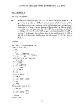
  • 1. SECTION 15 – FLEXIBLE POWER-TRANSMITTING ELEMENTS 757 LEATHER BELTS DESIGN PROBLEMS 841. A belt drive is to be designed for 321 =FF , while transmitting 60 hp at 2700 rpm of the driver 1D ; 85.1≈wm ; use a medium double belt, cemented joint, a squirrel-cage, compensator-motor drive with mildly jerking loads; center distance is expected to be about twice the diameter of larger pulley. (a) Choose suitable iron-pulley sizes and determine the belt width for a maximum permissible psis 300= . (b) How does this width compare with that obtained by the ALBA procedure? (c) Compute the maximum stress in the straight port of the ALBA belt. (d) If the belt in (a) stretches until the tight tension lbF 5251 = ., what is 21 FF ? Solution: (a) Table 17.1, Medium Double Ply, Select inD 71 = . min. int 64 20 = ( )( ) fpm nD vm 4948 12 27007 12 11 === ππ fpmfpmfpm 600049484000 << ( ) 000,33 21 mvFF hp − = ( )( ) 000,33 4948 60 21 FF − = lbFF 40021 =− 21 3FF = lbFF 4003 22 =− lbF 2002 = ( ) lbFF 60020033 21 === sbtF =1 η300=ds For cemented joint, 0.1=η psisd 300= ( )( )       == 64 20 3006001 bF inb 4.6= say inb 5.6=
  • 2. SECTION 15 – FLEXIBLE POWER-TRANSMITTING ELEMENTS 758 (b) ALBA Procedure ( )( )( )L21 1.17., ffpm CCCbCTableinhphp = Table 17.1, fpmvm 4948= Medium Double Ply 448.12=inhp Table 17.2 Squirrel cage, compensator, starting 67.0=mC Pulley Size, inD 71 = 6.0=pC Jerky loads, 83.0=fC ( )( )( )( )( )83.06.067.0448.1260 bhp == inb 5.14= say inb 15= (c) ( )( ) psi bt F s 128 64 20 151 6001 =       == η (d) ( ) ( )2 1 2 1 2 1 2 2 1 1 2 1 2006002 +=+= FFFo lbFo 2.373= lbF 5251 = ( ) ( ) 2 1 2 2 1 2 1 5252.3732 F+= lbF 2472 = 1255.2 247 525 2 1 == F F 842. A 20-hp, 1750 rpm, slip-ring motor is to drive a ventilating fan at 330 rpm. The horizontal center distance must be about 8 to 9 ft. for clearance, and operation is continuous, 24 hr./day. (a) What driving-pulley size is needed for a speed recommended as about optimum in the Text? (b) Decide upon a pulley size (iron or steel) and belt thickness, and determine the belt width by the ALBA tables. (c) Compute the stress from the general belt equation assuming that the applicable coefficient of friction is that suggested by the Text. (d) Suppose the belt is installed with an initial tension inlbFo 70= . (§17.10), compute 21 FF and the stress on the tight side if the approximate relationship of the operating tensions and the initial tensions is 2 1 2 1 2 2 1 1 2 oFFF =+ .
  • 3. SECTION 15 – FLEXIBLE POWER-TRANSMITTING ELEMENTS 759 Solution: fpmtovm 45004000= assume fpmvm 4250= 12 11nD vm π = ( ) 12 1750 4250 1Dπ = inD 26.91 = say inD 101 = (b) Using Heavy Double Ply Belt, int 64 23 = Minimum pulley diameter for fpmvm 4250≈ , inD 101 = Use inD 101 = ( )( ) fpm nD vm 4581 12 175010 12 11 === ππ ALBA Tables ( )( )( )L21 1.17., ffpm CCCbCTableinhphp = 8.13=inhp Slip ring motor, 4.0=mC Pulley Size, inD 101 = 7.0=pC Table 17.7, 24 hr/day, continuous 8.1=sfN Assume 74.0=fC ( )( ) ( )( )( )( )( )74.07.04.08.13208.1 bhp == inb 59.12= use inb 13= (c) General belt equation       −       −=− θ θ ρ f f s e ev sbtFF 1 2.32 12 2 21 fpsvs 35.76 60 4581 == ..035.0 inculb=ρ for leather int 64 23 = inb 13=
  • 4. SECTION 15 – FLEXIBLE POWER-TRANSMITTING ELEMENTS 760 ( )( ) lbFF 260 4581 208.1000,33 21 ==− 3.0=f on iron or steel C DD 12 − ±≈ πθ ftC 9~8= use 8.5 ft ( ) inD 5310 330 1750 2 =      = ( ) rad72.2 125.8 1053 = − −= πθ ( )( ) 816.072.23.0 ==θf 5578.0 11 816.0 816.0 = − = − e e e e f f θ θ ( ) ( )( ) ( )5578.0 2.32 35.76035.012 64 23 13260 2 21       −      ==− sFF psis 176= (d) 2 1 2 1 2 2 1 1 2 oFFF =+ ( )( ) lbininlbFo 9101370 == lbFF 26021 =− lbFF 26012 −= ( ) ( ) 33.609102260 2 1 2 1 1 2 1 1 ==−+ FF lbF 10451 = lbF 78526010452 =−= ( ) psi bt F s 224 64 23 13 10451 =       == 331.1 785 1045 2 1 == F F 843. A 100-hp squirrel-cage, line-starting electric motor is used to drive a Freon reciprocating compressor and turns at 1140 rpm; for the cast-iron motor pulley, inD 161 = ; inD 532 = , a flywheel; cemented joints;l ftC 8= . (a) Choose an appropriate belt thickness and determine the belt width by the ALBA tables. (b) Using the design stress of §17.6, compute the coefficient of friction that would be needed. Is this value satisfactory? (c) Suppose that in the beginning, the initial tension was set so that the operating 221 =FF . Compute the maximum stress in a straight part. (d) The approximate relation of the operating tensions and the
  • 5. SECTION 15 – FLEXIBLE POWER-TRANSMITTING ELEMENTS 761 initial tension oF is 2 1 2 1 2 2 1 1 2 oFFF =+ . For the condition in (c), compute oF . Is it reasonable compared to Taylor’s recommendation? Solution: (a) Table 17.1 ( )( ) fpm nD vm 4775 12 114016 12 11 === ππ Use heavy double-ply belt int 64 23 = 1.14=inhp ( )( )( )L21 1.17., ffpm CCCbCTableinhphp = line starting electric motor , 5.0=mC Table 17.7, squirrel-cage, electric motor, line starting, reciprocating compressor 4.1=sfN inD 161 = , 8.0=pC assume, 74.0=fC ( )( ) hphp 1401004.1 == ( )( )( )( )( )74.08.05.01.14140 bhp == inb 5.33= use inb 34= (b) §17.6, η400=ds 00.1=η for cemented joint. psisd 400=       −       −=− θ θ ρ f f s e ev sbtFF 1 2.32 12 2 21 fpsvs 6.79 60 4775 == ..035.0 inculb=ρ for leather int 64 23 = inb 34= ( )( ) lbFF 968 4775 1004.1000,33 21 ==− ( ) ( )( )       −       −      ==− θ θ f f e e FF 1 2.32 6.79035.012 400 64 23 34968 2 21
  • 6. SECTION 15 – FLEXIBLE POWER-TRANSMITTING ELEMENTS 762 2496.0 1 = − θ θ f f e e 28715.0=θf C DD 12 − ±≈ πθ ftC 8= ( ) rad7562.2 128 1653 = − −= πθ ( ) 28715.07562.2 =f 3.01042.0 <=f Therefore satisfactory. (c) lbFF 96821 =− 21 2FF = lbFF 9682 22 =− ( ) lbFF 193696822 21 === ( ) psi bt F s 159 64 23 34 19361 =       == (d) lbF 19361 = , lbF 9682 = 2 1 2 2 1 1 2 1 2 FFFo += ( ) ( )2 1 2 1 2 1 96819362 +=oF lbFo 1411= inlbFo 5.41 34 1411 == of width is less than Taylor’s recommendation and is reasonable. 844. A 50-hp compensator-started motor running at 865 rpm drives a reciprocating compressor for a 40-ton refrigerating plant, flat leather belt, cemented joints. The diameter of the fiber driving pulley is 13 in., inD 702 = ., a cast-iron flywheel; .11.6 inftC = Because of space limitations, the belt is nearly vertical; the surroundings are quite moist. (a) Choose a belt thickness and determine the width by the ALBA tables. (b) Using recommendations in the Text, compute s from the general belt equation. (c) With this value of s , compute 1F and 21 FF . (d) Approximately, 2 1 2 1 2 2 1 1 2 oFFF =+ , where oF is the initial tension. For the condition in (c), what should be the initial tension? Compare with Taylor, §17.10. (e) Compute the belt length. (f) The data are from an actual drive. Do you have any recommendations for redesign on a more economical basis?
  • 7. SECTION 15 – FLEXIBLE POWER-TRANSMITTING ELEMENTS 763 Solution: (a) ( )( ) fpm nD vm 2944 12 86513 12 11 === ππ Table 17.1, use Heavy Double Ply, inD 9min = for fpmvm 2944= belts less than 8 in wide int 64 23 = ( )( )( )L21 1.17., ffpm CCCbCTableinhphp = 86.9=inhp Table 17.2 67.0=mC 8.0=pC ( )( ) 61420830740 ... ==fC Table 17.7, electric motor, compensator-started (squirrel cage) and reciprocating compressor 4.1=sfN ( )( ) hphp 70504.1 == ( )( )( )( )( )614208067086970 .... bhp == inb 621.= use inb 25= (b) General Belt Equation       −       −=− θ θ ρ f f s e ev sbtFF 1 2.32 12 2 21 inb 25= int 64 23 = ..035.0 inculb=ρ for leather fpsvs 1.49 60 2944 == Leather on iron, 3.0=f C DD 12 − −= πθ ( ) rad4552 11126 1370 .= + − −=πθ ( )( ) 73650455230 ... ==θf
  • 8. SECTION 15 – FLEXIBLE POWER-TRANSMITTING ELEMENTS 764 52120 11 73650 73650 .. . = − = − e e e e f f θ θ ( )( ) lbFF 785 2944 504.1000,33 21 ==− ( ) ( )( ) ( )52120 232 149035012 64 23 25785 2 21 . . ..       −      ==− sFF psis 199= Cemented joint, 0.1=η psis 199= (c) ( )( ) lbsbtF 1788 64 23 251991 =      == lbF 100378517882 =−= 7831 1003 1788 2 1 .== F F (d) 2 1 2 2 1 1 2 1 2 FFFo += ( ) ( )2 1 2 1 2 1 100317882 +=oF lbFo 1367= inlbFo 754 25 1367 .== Approximately less than Taylor’s recommendation ( = 70 lb/in.) (e) ( ) ( ) C DD DDCL 4 57.12 2 12 12 − +++≈ ( )( )[ ] ( ) ( ) ( )( )[ ] inL 306 111264 1370 1370571111262 2 = + − ++++= . (f) More economical basis 12 11nD vm π = ( ) 12 865 4500 1Dπ = inD 87.191 = use inD 201 =
  • 9. SECTION 15 – FLEXIBLE POWER-TRANSMITTING ELEMENTS 765 CHECK PROBLEMS 846. An exhaust fan in a wood shop is driven by a belt from a squirrel-cage motor that runs at 880 rpm, compensator started. A medium double leather belt, 10 in. wide is used; inC 54= .; inD 141 = . (motor), inD 542 = ., both iron. (a) What horsepower, by ALBA tables, may this belt transmit? (b) For this power, compute the stress from the general belt equation. (c) For this stress, what is 21 FF ? (d) If the belt has stretched until psis 200= on the tight side, what is 21 FF ? (e) Compute the belt length. Solution: (a) For medium double leather belt int 64 20 = ( )( ) fpm CCCbinhphp = Table 17.1 and 17.2 67.0=mC 8.0=pC 74.0=fC inb 10= ( )( ) fpm nD vm 3225 12 88014 12 11 === ππ 6625.6=inhp ( )( )( )( )( ) hphp 43.2674.08.067.0106625.6 == (b)       −       −=− θ θ ρ f f s e ev sbtFF 1 2.32 12 2 21 inb 10= int 64 20 = ..035.0 inculb=ρ fpsvs 75.53 60 3225 == C DD 12 − −= πθ rad4.2 54 1454 = − −= πθ Leather on iron 3.0=f ( )( ) 72.04.23.0 ==θf
  • 10. SECTION 15 – FLEXIBLE POWER-TRANSMITTING ELEMENTS 766 51325.0 11 72.0 72.0 = − = − e e e e f f θ θ ( ) lbFF 270 3225 43.26000,33 21 ==− ( ) ( )( ) ( )51325.0 2.32 75.53035.012 64 20 10270 2 21       −      ==− sFF psis 206= (c) ( )( ) lbsbtF 644 64 20 102061 =      == lbF 3742706442 =−= 72.1 374 644 2 1 == F F (d) psis 200= ( )( ) lbsbtF 625 64 20 102001 =      == lbF 3552706252 =−= 76.1 355 625 2 1 == F F (e) ( ) ( ) C DD DDCL 4 57.12 2 12 12 − +++≈ ( ) ( ) ( ) ( ) inL 222 544 1454 145457.1542 2 = − +++= 847. A motor is driving a centrifugal compressor through a 6-in. heavy, single-ply leather belt in a dusty location. The 8-in motor pulley turns 1750 rpm; inD 122 = . (compressor shaft); ftC 5= . The belt has been designed for a net belt pull of inlbFF 4021 =− of width and 321 =FF . Compute (a) the horsepower, (b) the stress in tight side. (c) For this stress, what needed value of f is indicated by the general belt equation? (d) Considering the original data,what horsepower is obtained from the ALBA tables? Any remarks? Solution: (a) ( )( ) fpm nD vm 3665 12 17508 12 11 === ππ inb 6= ( )( ) lbFF 24064021 ==−
  • 11. SECTION 15 – FLEXIBLE POWER-TRANSMITTING ELEMENTS 767 ( ) ( )( ) hp vFF hp m 65.26 000,33 3665240 000,33 21 == − = (b) 21 3FF = lbFF 2403 22 =− lbF 1202 = lbF 3601 = bt F s 1 = For heavy single-ply leather belt int 64 13 = ( ) psis 295 64 13 6 360 =       = (c)       −       −=− θ θ ρ f f s e ev sbtFF 1 2.32 12 2 21 ..035.0 inculb=ρ fpsvs 1.61 60 3665 == lbFF 24021 =− ( ) ( )( )       −       −      ==− θ θ f f e e FF 1 2.32 1.61035.012 295 64 13 6240 2 21 7995.0 1 = − θ θ f f e e C DD 12 − −= πθ ( ) rad075.3 125 812 = − −= πθ 9875.4=θf e 607.1=θf ( ) 607.1075.3 =f 5226.0=f (d) ALBA Tables (Table 17.1 and 17.2) ( )( ) fpm CCCbinhphp = fpmvm 3665= 965.6=inhp
  • 12. SECTION 15 – FLEXIBLE POWER-TRANSMITTING ELEMENTS 768 inb 10= 0.1=mC (assumed) 6.0=pC 74.0=fC ( )( )( )( )( ) hphphp 65.266.1874.06.00.16965.6 <== 848. A 10-in. medium double leather belt, cemented joints, transmits 60 hp from a 9- in. paper pulley to a 15-in. pulley on a mine fab; dusty conditions. The compensator-started motor turns 1750 rpm; inC 42= . This is an actual installation. (a) Determine the horsepower from the ALBA tables. (b) Using the general equation, determine the horsepower for this belt. (c) Estimate the service factor from Table 17.7 and apply it to the answer in (b). Does this result in better or worse agreement of (a) and (b)? What is your opinion as to the life of the belt? Solution: ( )( ) fpm nD vm 4123 12 17509 12 11 === ππ (a) ( )( ) fpm CCCbinhphp = Table 17.1 and 17.2 Medium double leather belt int 64 20 = fpmvm 4123= 15.11=inhp 67.0=mC 7.0=pC 74.0=fC inb 10= ( )( )( )( )( ) hphp 7.3874.07.067.01015.11 == (b)       −       −=− θ θ ρ f f s e ev sbtFF 1 2.32 12 2 21 inb 10= ..035.0 inculb=ρ η400=s 0.1=η cemented joint psis 400= C DD 12 − −= πθ
  • 13. SECTION 15 – FLEXIBLE POWER-TRANSMITTING ELEMENTS 769 rad9987.2 42 915 = − −= πθ Leather on paper pulleys, 5.0=f ( )( ) 5.19987.25.0 ==θf 77687.0 1 = − θ θ f f e e fpsvs 72.68 60 4123 == ( ) ( )( ) ( ) lbFF 82277687.0 2.32 72.68035.012 400 64 20 10 2 21 =      −      =− ( ) ( )( ) hp vFF hp m 7.102 000,33 4123822 000,33 21 == − = (c) Table 17.7 6.1=sfN hphphp 7.1022.64 6.1 7.102 <== Therefore, better agreement Life of belt, not continuous, hphp 7.3860 > . MISCELLANEOUS 849. Let the coefficient of friction be constant. Find the speed at which a leather belt may transmit maximum power if the stress in the belt is (a) 400 psi, (b) 320 psi. (c) How do these speeds compare with those mentioned in §17.9, Text? (d) Would the corresponding speeds for a rubber belt be larger or smaller? (HINT: Try the first derivative of the power with respect to velocity.) Solution:       −       −=− θ θ ρ f f s e ev sbtFF 1 2.32 12 2 21 ( ) 000,33 21 mvFF hp − = ( ) 000,33 60 21 svFF hp − =       −       −= θ θ ρ f f ss e ev s btv hp 1 2.32 12 000,33 60 2 s s f f v v s e ebt hp       −      − = 2.32 121 000,33 60 2 ρ θ θ
  • 14. SECTION 15 – FLEXIBLE POWER-TRANSMITTING ELEMENTS 770 ( ) ( ) 0 2.32 24 2.32 121 000,33 60 22 =      −      −      − = ss f f s vv s e ebt vd hpd ρρ θ θ 2.32 36 2 sv s ρ = ..035.0 inculb=ρ (a) psis 400= ( ) 2.32 035.036 400 2 sv = fpsvs 105.101= fpmvm 6066= (b) psis 320= ( ) 2.32 035.036 320 2 sv = fpsvs 431.90= fpmvm 5426= (c) Larger than those mentioned in §17.9 (4000 – 4500 fpm) (d) Rubber belt, ..045.0 inculb=ρ (a) psis 400= ( ) 2.32 045.036 400 2 sv = fpsvs 166.89= fpmfpmvm 60665350 <= Therefore, speeds for a rubber belt is smaller. 850. A 40-in. pulley transmits power to a 20-in. pulley by means of a medium double leather belt, 20 in. wide; ftC 14= , let 3.0=f . (a) What is the speed of the 40-in pulley in order to stress the belt to 300 psi at zero power? (b) What maximum horsepower can be transmitted if the indicated stress in the belt is 300 psi? What is the speed of the belt when this power is transmitted? (See HINT in 849). Solution:       −       −=− θ θ ρ f f s e ev sbtFF 1 2.32 12 2 21
  • 15. SECTION 15 – FLEXIBLE POWER-TRANSMITTING ELEMENTS 771 ( ) 000,33 60 21 svFF hp − = s s f f v v s e ebt hp       −      − = 2.32 121 000,33 60 2 ρ θ θ ( ) ( ) 0 2.32 24 2.32 121 000,33 60 22 =      −      −      − = ss f f s vv s e ebt vd hpd ρρ θ θ 2.32 36 2 sv s ρ = for maximum power (a) At zero power: 2.32 12 2 sv s ρ = psis 300= ..035.0 inculb=ρ ( ) 2.32 035.012 300 2 sv = fpsvs 6575.151= fpmvm 9100= Speed, 40 in pulley, ( ) ( ) rpm D v n m 869 40 91001212 2 2 === ππ (b) Maximum power 2.32 36 2 sv s ρ = ( ) 2.32 035.036 300 2 sv = fpsvs 5595.87= fpmvm 5254= s s f f v v s e ebt hp       −      − = 2.32 121 000,33 60 2 ρ θ θ int 64 20 = inb 20= C DD 12 − −= πθ ( ) rad0225.3 1214 2040 = − −= πθ 3.0=f
  • 16. SECTION 15 – FLEXIBLE POWER-TRANSMITTING ELEMENTS 772 ( )( ) 90675.00225.33.0 ==θf 5962.0 1 = − θ θ f f e e ( ) ( ) ( )( ) ( ) 64.1185595.87 2.32 5595.87035.012 3005962.0 000,33 64 20 2060 2 =      −       =hp fpmvm 5254= AUTOMATIC TENSION DEVICES 851. An ammonia compressor is driven by a 100-hp synchronous motor that turns 1200 rpm; 12-in. paper motor pulley; 78-in. compressor pulley, cast-iron; inC 84= . A tension pulley is placed so that the angle of contact on the motor pulley is 193o and on the compressor pulley, 240o . A 12-in. medium double leather belt with a cemented joint is used. (a) What will be the tension in the tight side of the belt if the stress is 375 psi? (b) What will be the tension in the slack side? (c) What coefficient of friction is required on each pulley as indicated by the general equation? (d) What force must be exerted on the tension pulley to hold the belt tight, and what size do you recommend? Solution: (a) sbtF =1 inb 12= int 64 20 = ( )( )       = 64 20 123751F (b) mv hp FF 000,33 21 =− ( )( ) fpm nD vm 3770 12 120012 12 11 === ππ Table 17.7, 2.1=sfN ( )( ) lbFF 1050 3770 1002.1000,33 21 ==− lbFF 35610501406105012 =−=−= (c)       −       −=− θ θ ρ f f s e ev sbtFF 1 2.32 12 2 21 fpsvs 83.62 60 3770 ==
  • 17. SECTION 15 – FLEXIBLE POWER-TRANSMITTING ELEMENTS 773 ..035.0 inculb=ρ ( ) ( )( )       −     −      = θ θ f f e e 1 2.32 83.62035.012 375 64 20 121050 8655.0 1 = − θ θ f f e e 006.2=θf Motor pulley rad3685.3 180 193193 =      == π θ o ( ) 006.23685.3 =f 5955.0=f Compressor Pulley rad1888.4 180 2402403 =      == π θ o ( ) 006.21888.4 =f 4789.0=f (d) Force: Without tension pulley rad C DD 356.2 84 127812 1 = − −= − −= ππθ rad C DD 9273.3 84 127812 2 = − += − += ππθ
  • 18. SECTION 15 – FLEXIBLE POWER-TRANSMITTING ELEMENTS 774 o 5.356197.0 2 356.2 356.23685.3 2 1 111 == − −−= − −−′= rad πθπ θθα o 5.376544.09273.31888.4 2 9273.3 2 22 2 2 ==−+ − =−′+ − = rad π θθ πθ α ( ) ( ) lbFQ 16725.37sin5.35sin1406sinsin 211 =+=+= αα of force exerted Size of pulley; For medium double leather belt, fpmvm 3770= , width = inin 812 > inD 826 =+=
  • 19. SECTION 15 – FLEXIBLE POWER-TRANSMITTING ELEMENTS 775 852. A 40-hp motor, weighing 1915 lb., runs at 685 rpm and is mounted on a pivoted base. In Fig. 17.11, Text, ine 10= ., inh 16 3 19= . The center of the 11 ½-in. motor pulley is 11 ½ in. lower than the center of the 60-in. driven pulley; inC 48= . (a) With the aid of a graphical layout, find the tensions in the belt for maximum output of the motor if it is compensator started. What should be the width of the medium double leather belt if psis 300= ? (c) What coefficient of friction is indicated by the general belt equation? (Data courtesy of Rockwood Mfg. Co.) Solution: (a) lbR 1915= Graphically inb 26≈ ina 9≈ [ ]∑ = 0BM bFaFeR 21 += ( )( ) ( )( ) ( )( )269191510 21 FF += 150,19269 21 =+ FF For compensator started ( ) ( ) hphpratedhp 56404.14.1 === mv hp FF 000,33 21 =−
  • 20. SECTION 15 – FLEXIBLE POWER-TRANSMITTING ELEMENTS 776 ( )( ) fpm nD vm 2062 12 6855.11 12 11 === ππ ( ) lbFF 896 2062 56000,33 21 ==− 89612 −= FF Substituting ( ) 150,19896269 11 =−+ FF lbF 12131 = lbF 31789612132 =−= For medium leather belt, int 64 20 = sbtF =1 ( )( )       = 64 20 3001213 b inb 13= (c)       −       −=− θ θ ρ f f s e ev sbtFF 1 2.32 12 2 21 fpsvs 37.34 60 2062 == ..035.0 inculb=ρ ( ) ( )( )       −     −      = θ θ f f e e 1 2.32 37.34035.012 300 64 20 13896 775.0 1 = − θ θ f f e e 492.1=θf rad C DD 1312.2 48 5.116012 = − −= − −= ππθ ( ) 492.11312.2 =f 70.0=f 853. A 50-hp motor, weighing 1900 lb., is mounted on a pivoted base, turns 1140 rpm, and drives a reciprocating compressor; in Fig. 17.11, Text, ine 4 3 8= ., inh 16 5 17= . The center of the 12-in. motor pulley is on the same level as the center of the 54-in. compressor pulley; inC 40= . (a) With the aid of a graphical layout, find the tensions in the belt for maximum output of the motor if it is compensator started. (b) What will be the stress in the belt if it is a heavy double
  • 21. SECTION 15 – FLEXIBLE POWER-TRANSMITTING ELEMENTS 777 leather belt, 11 in. wide? (c) What coefficient of friction is indicated by the general belt equation? (Data courtesy of Rockwood Mfg. Co.) Solution: (a) For compensator-started ( ) hphp 70504.1 == mv hp FF 000,33 21 =− ( )( ) fpm nD vm 3581 12 114012 12 11 === ππ ( ) lbFF 645 2062 70000,33 21 ==− inb 25≈ ina 5≈ lbR 1900= bFaFeR 21 += ( )( ) ( ) ( )255190075.8 21 FF += lbFF 33255 21 =+ lbFF 33255645 22 =++ lbF 4472 = lbFF 1092447645645 21 =+=+= (b) For heavy double leather belt int 64 23 = inb 11=
  • 22. SECTION 15 – FLEXIBLE POWER-TRANSMITTING ELEMENTS 778 ( ) psi bt F s 276 64 20 11 10921 =       == (c)       −       −=− θ θ ρ f f s e ev sbtFF 1 2.32 12 2 21 fpsvs 68.59 60 3581 == ..035.0 inculb=ρ ( ) ( )( )       −     −      = θ θ f f e e 1 2.32 68.59035.012 276 64 23 11645 241.1=θf rad C DD 092.2 40 125412 = − −= − −= ππθ ( ) 492.1092.2 =f 60.0=f RUBBER BELTS 854. A 5-ply rubber belt transmits 20 horsepower to drive a mine fan. An 8-in., motor pulley turns 1150 rpm; inD 362 = ., fan pulley; ftC 23= . (a) Design a rubber belt to suit these conditions, using a net belt pull as recommended in §17.15, Text. (b) Actually, a 9-in., 5-ply Goodrich high-flex rubber belt was used. What are the indications for a good life? Solution: (a) ( ) o 174040.3 1223 83612 == − −= − −= rad C DD ππθ 976.0=θK 2400 θKNbv hp pm = 976.0=θK ( )( ) fpm nD vm 2409 12 11508 12 11 === ππ 5=pN ( )( )( ) 2400 976.052409 20 b hp == inb 1.4= min. inb 5=
  • 23. SECTION 15 – FLEXIBLE POWER-TRANSMITTING ELEMENTS 779 (b) With inb 9= is safe for good life. 855. A 20-in., 10-ply rubber belt transmits power from a 300-hp motor, running at 650 rpm, to an ore crusher. The center distance between the 33-in. motor pulley and the 108-in. driven pulley is 18 ft. The motor and crusher are so located that the belt must operate at an angle 75o with the horizontal. What is the overload capacity of this belt if the rated capacity is as defined in §17.15, Text? Solution: 2400 pm Nbv hp = inb 20= ( )( ) fpm nD vm 5616 12 65033 12 11 === ππ 10=pN ( )( )( ) hphp 468 2400 10561620 == Overlaod Capacity = ( ) %56%100 300 300468 = − V-BELTS NOTE: If manufacturer’s catalogs are available, solve these problems from catalogs as well as from data in the Text. 856. A centrifugal pump, running at 340 rpm, consuming 105 hp in 24-hr service, is to be driven by a 125-hp, 1180-rpm, compensator-started motor; intoC 4943= . Determine the details of a multiple V-belt drive for this installation. The B.F. Goodrich Company recommended six C195 V-belts with 14.4-in. and 50-in. sheaves; inC 2.45≈ . Solution: Table 17.7 4.12.02.1 =+=sfN (24 hr/day) Design hp = sfN (transmitted hp) = ( )( ) hp1751254.1 = Fig. 17.4, 175 hp, 1180 rpm inD 13min = , D-section 4.14 50 340 1180 1 2 == D D use ininD 134.141 >= inD 502 =
  • 24. SECTION 15 – FLEXIBLE POWER-TRANSMITTING ELEMENTS 780 ( )( ) fpm nD vm 4449 12 11804.14 12 11 === ππ 36 2 1 09.0 3 1010 10 mm dm vv e DK c v ahpRated         −−      = Table 17.3, D-section 788.18=a , 7.137=c , 0848.0=e Table 17.4, 47.3 1 2 = D D 14.1=dK ( )( ) ( )( ) hphpRated 294.28 10 4449 10 4449 0848.0 4.1414.1 7.137 4449 10 788.18 36 209.03 =         −−      = Back to Fig. 17.14, C-section must be used. 792.8=a , 819.38=c , 0416.0=e 36 2 1 09.0 3 1010 10 mm dm vv e DK c v ahpRated         −−      = ( )( ) ( )( ) hphpRated 0.20 10 4449 10 4449 0416.0 4.1414.1 819.38 4449 10 792.8 36 209.03 =         −−      = Adjusted rated hp = ( )hpratedKK Lθ Table 17.5, 77.0 46 4.145012 = − = − C DD 88.0=θK Table 17.6 ( ) ( ) C DD DDCL 4 57.12 2 12 12 − +++≈ ( ) ( ) ( ) ( ) inL 200 464 4.1450 4.145057.1462 2 = − +++= use C195, inL 9.197= 07.1=LK Adjusted rated hp = ( )( )( ) hp83.182007.188.0 = belts hpratedAdjusted hpDesign beltsofNo 3.9 83.18 175 . === use 9 belts Use 9 , C195 V-belts with 14.4 in and 50 in sheaves
  • 25. SECTION 15 – FLEXIBLE POWER-TRANSMITTING ELEMENTS 781 ( ) 16 32 2 12 2 DDBB C −−+ = ( ) ( ) ( ) inDDLB 2.3874.145028.69.197428.64 12 =+−=+−= ( ) ( ) inC 9.44 16 4.1450322.3872.387 22 = −−+ = 857. A 50-hp, 1160-rpm, AC split-phase motor is to be used to drive a reciprocating pump at a speed of 330 rpm. The pump is for 12-hr. service and normally requires 44 hp, but it is subjected to peak loads of 175 % of full load; inC 50≈ . Determine the details of a multiple V-belt drive for this application. The Dodge Manufacturing Corporation recommended a Dyna-V Drive consisting of six 5V1800 belts with 10.9-in. and 37.5-in. sheaves; inC 2.50≈ . Solution: Table 17.7, (12 hr/day) 2.12.04.1 =−=sfN Design hp = ( )( )( ) hp1055075.12.1 = Fig. 17.4, 105 hp, 1160 rpm inD 13min = , D-section 2.13 4.46 330 1160 1 2 ≈= D D use ininD 132.131 >= inD 4.462 = ( )( ) fpm nD vm 4009 12 11602.13 12 11 === ππ 36 2 1 09.0 3 1010 10 mm dm vv e DK c v ahpRated         −−      = Table 17.3, D-section 788.18=a , 7.137=c , 0848.0=e Table 17.4, 5.3 2.13 4.46 1 2 == D D 14.1=dK ( )( ) ( )( ) hphpRated 32.24 10 4009 10 4009 0848.0 2.1314.1 7.137 4009 10 788.18 36 209.03 =         −−      = Back to Fig. 17.14, C-section must be used. 792.8=a , 819.38=c , 0416.0=e inD 9min =
  • 26. SECTION 15 – FLEXIBLE POWER-TRANSMITTING ELEMENTS 782 1.9 32 330 1160 1 2 ≈= D D use inD 1.91 = ( )( ) fpm nD vm 2764 12 11601.9 12 11 === ππ ( )( ) ( )( ) hphpRated 96.10 10 2764 10 2764 0416.0 1.914.1 819.38 2764 10 792.8 36 209.03 =         −−      = Adjusted rated hp = ( )hpratedKK Lθ Table 17.5, 458.0 50 1.93212 = − = − C DD 935.0=θK Table 17.6 ( ) ( ) C DD DDCL 4 57.12 2 12 12 − +++≈ ( ) ( ) ( ) ( ) inL 167 504 1.932 1.93257.1502 2 = − +++= use C158, inL 9.160= 02.1=LK Adjusted rated hp = ( )( )( ) hp45.1096.1002.1935.0 = belts hpratedAdjusted hpDesign beltsofNo 10 43.10 105 . === ( ) 16 32 2 12 2 DDBB C −−+ = ( ) ( ) ( ) inDDLB 5.3851.93228.69.160428.64 12 =+−=+−= ( ) ( ) inC 8.46 16 1.932325.3855.385 22 = −−+ = Use 10-C158 belts, inD 1.91 = inD 322 = , inC 8.46= 858. A 200-hp, 600-rpm induction motor is to drive a jaw crusher at 125 rpm; starting load is heavy; operating with shock; intermittent service; intoC 123113= . Recommend a multiple V-flat drive for this installation. The B.F. Goodrich Company recommended eight D480 V-belts with a 26-in. sheave and a 120.175- in. pulley; inC 3.116≈ . Solution:
  • 27. SECTION 15 – FLEXIBLE POWER-TRANSMITTING ELEMENTS 783 Table 17.7 4.12.06.1 =−=sfN ( )( ) hphp 2802004.1 == Fig. 17.14, 280 hp, 600 rpm Use Section E But in Table 17.3, section E is not available, use section D 13min =D 8.4 125 600 1 2 == D D For max1D : 1 21 2 min D DD C + + = 1 11 2 8.4 113 D DD + + = inD 281 = 2min DC = inD 1132 = inD 5.23 8.4 113 1 == use ( ) inD 185.2313 2 1 1 =+≈ ( )( ) inD 4.86188.42 == ( ) ( ) C DD DDCL 4 57.12 2 12 12 − +++≈ ( ) ( ) ( ) ( ) inL 410 1184 184.86 184.8657.11182 2 = − +++= using inD 191 = , inD 2.912 = , inC 118= ( ) ( ) ( ) ( ) inL 420 1184 192.91 192.9157.11182 2 = − +++= Therefore use D420 sections inD 191 = , inD 2.912 = ( )( ) fpm nD vm 2985 12 60019 12 11 === ππ 36 2 1 09.0 3 1010 10 mm dm vv e DK c v ahpRated         −−      = Table 17.3, D-section 788.18=a , 7.137=c , 0848.0=e Table 17.4, 8.4 1 2 = D D
  • 28. SECTION 15 – FLEXIBLE POWER-TRANSMITTING ELEMENTS 784 14.1=dK ( )( ) ( )( ) hphpRated 6.29 10 2985 10 2985 0848.0 1914.1 7.137 2985 10 788.18 36 209.03 =         −−      = Therefore, Fig. 17.14, section D is used. Adjusted rated hp = ( )hpratedKK Lθ Table 17.5, 612.0 118 192.9112 = − = − C DD 83.0=θK (V-flat) Table 17.6, D420 inL 8.420= 12.1=LK Adjusted rated hp = ( )( )( ) hp52.276.2912.183.0 = belts hpratedAdjusted hpDesign beltsofNo 10 52.27 280 . === Use10 , D420, inD 191 = , inD 2.912 = , inC 118= 859. A 150-hp, 700-rpm, slip-ring induction motor is to drive a ball mill at 195 rpm; heavy starting load; intermittent seasonal service; outdoors. Determine all details for a V-flat drive. The B.F. Goodrich Company recommended eight D270 V- belts, 17.24-in sheave, 61-in. pully, inC 7.69≈ . Solution: Table 17.7, 4.12.06.1 =−=sfN Design hp = ( )( ) hp2101504.1 = Fig. 17.4, 210 hp, 700 rpm inD 13min = , D-section 36 2 1 09.0 3 1010 10 mm dm vv e DK c v ahpRated         −−      = For Max. Rated hp, ( ) 0 103 =       mv d hpd 3 33 1 91.0 3 101010       −      −      = mm d m v e v DK cv ahpRated Let 3 10 mv X =
  • 29. SECTION 15 – FLEXIBLE POWER-TRANSMITTING ELEMENTS 785 3 1 91.0 eXX DK c aXhp d −−= ( ) 3 1 3 11 3 1012 700 101210 × = × == DnDv X m ππ π700 1012 3 1 X D × = 3 3 91.0 1012 700 eX K c aXhp d − × −= π ( ) ( ) 0391.0 209.0 =−= − eXaX Xd hpd e a X 3 91.009.2 = Table 17.3, D-section 788.18=a , 7.137=c , 0848.0=e ( ) ( )0848.03 788.1891.0 10 09.2 3 09.2 =      = mv X fpmvm 7488= 7488 12 11 == nD vm π ( ) 7488 12 7001 == D vm π inD 86.401 = max inD 86.401 = ave. ( ) inD 93.2686.4013 2 1 1 =+= use inD 221 = 22 79 195 700 1 2 ≈= D D inD 221 = , inD 792 = Min. inD DD C 5.7222 2 7922 2 1 21 =+ + =+ + = Or Min. inDC 792 == ( ) ( ) C DD DDCL 4 57.12 2 12 12 − +++≈ ( ) ( ) ( ) ( ) inL 327 794 2279 227957.1792 2 = − +++= use D330, inL 8.330= ( ) 16 32 2 12 2 DDBB C −−+ =
  • 30. SECTION 15 – FLEXIBLE POWER-TRANSMITTING ELEMENTS 786 ( ) ( ) ( ) inDDLB 689227928.68.330428.64 12 =+−=+−= ( ) ( ) inC 12.81 16 227932689689 22 = −−+ = ( )( ) fpm nD vm 4032 12 70022 12 11 === ππ 14.1=dK ( )( ) ( )( ) hphpRated 124.39 10 4032 10 4032 0848.0 2214.1 7.137 4032 10 788.18 36 209.03 =         −−      = Adjusted rated hp = ( )hpratedKK Lθ Table 17.5, 70.0 12.81 227912 = − = − C DD 84.0=θK (V-flat) Table 17.6 D330 07.1=LK Adjusted rated hp = ( )( )( ) hp165.35124.3907.184.0 = belts hpratedAdjusted hpDesign beltsofNo 97.5 165.35 210 . === use 6 belts Use 6 , D330 V-belts , inD 221 = , inD 792 = , inC 1.81≈ 860. A 30-hp, 1160-rpm, squirrel-cage motor is to be used to drive a fan. During the summer, the load is 29.3 hp at a fan speed of 280 rpm; during the winter, it is 24 hp at 238 rpm; inC 5044 << .; 20 hr./day operation with no overload. Decide upon the size and number of V-belts, sheave sizes, and belt length. (Data courtesy of The Worthington Corporation.) Solution: Table 17.7 8.12.06.1 =+=sfN Design hp = ( )( ) hp54308.1 = Speed of fan at 30 hp ( ) rpmn 286238238280 243.29 2430 2 =+− − − = at 54 hp, 1160 rpm. Fig. 17.4 use either section C or section D Minimum center distance: 2DC =
  • 31. SECTION 15 – FLEXIBLE POWER-TRANSMITTING ELEMENTS 787 or 1 21 2 D DD C + + = 056.4 286 1160 1 2 == D D use 1056.4 DC = inCin 5044 << , use inC 47= inD 6.11 056.4 47 max1 == use C-section, inD 9min = Let inD 1101 .= , inD 412 = ( ) ( ) C DD DDCL 4 57.12 2 12 12 − +++≈ ( ) ( ) ( ) ( ) inL 3.179 474 1.1041 1.104157.1472 2 = − +++= use C137, inL 9.175= ( ) 16 32 2 12 2 DDBB C −−+ = ( ) ( ) ( ) inDDLB 7.3281.104128.69.175428.64 12 =+−=+−= ( ) ( ) ininC 442.45 16 1.1041327.3827.382 22 ≈= −−+ = C173, satisfies inCin 5044 << 3 33 1 91.0 3 101010       −      −      = mm d m v e v DK cv ahpRated ( )( ) fpm nD vm 3067 12 11601.10 12 11 === ππ Table 17.4 056.4 1 2 = D D , 14.1=dK Table 17.3, C-section 792.8=a , 819.38=c , 0416.0=e ( )( ) ( )( ) hphpRated 838.12 10 3067 10 3067 0416.0 1.1014.1 819.38 3067 10 792.8 36 209.03 =         −−      = Adjusted rated hp = ( )hpratedKK Lθ Table 17.5, 68.0 2.45 1.104112 = − = − C DD 90.0=θK
  • 32. SECTION 15 – FLEXIBLE POWER-TRANSMITTING ELEMENTS 788 Table 17.6 9.175=L , C173 04.1=LK Adjusted rated hp = ( )( )( ) hp02.12838.1204.190.0 = belts hpratedAdjusted hpDesign beltsofNo 5.4 02.12 54 . === use 5 belts Use 5 , C173 V-belts , inD 1.101 = , inD 412 = POWER CHAINS NOTE: If manufacturer’s catalogs are available, solve these problems from catalogs as well as from data in the Text. 861. A roller chain is to be used on a paving machine to transmit 30 hp from the 4- cylinder Diesel engine to a counter-shaft; engine speed 1000 rpm, counter-shaft speed 500 rpm. The center distance is fixed at 24 in. The cain will be subjected to intermittent overloads of 100 %. (a) Determine the pitch and the number of chains required to transmit this power. (b) What is the length of the chain required? How much slack must be allowed in order to have a whole number of pitches? A chain drive with significant slack and subjected to impulsive loading should have an idler sprocket against the slack strand. If it were possible to change the speed ratio slightly, it might be possible to have a chain with no appreciable slack. (c) How much is the bearing pressure between the roller and pin? Solution: (a) ( ) hphpdesign 60302 == intermittent 2 500 1000 2 1 1 2 ==≈ n n D D 12 2DD = in D DC 24 2 1 2 =+= 24 2 2 1 1 =+ D D inD 691 .max = ( ) inDD 2196922 12 ..maxmax === ( )( ) fpm nD vm 2513 12 10006.9 12 11 === ππ Table 17.8, use Chain No. 35, Limiting Speed = 2800 fpm
  • 33. SECTION 15 – FLEXIBLE POWER-TRANSMITTING ELEMENTS 789 Minimum number of teeth Assume 211 =N 422 12 == NN [Roller-Bushing Impact] 8.0 5.1 100 P n N Khp ts r       = Chain No. 35 inP 8 3 = 21=tsN rpmn 1000= 29=rK ( ) hphp 3.40 8 3 1000 21100 29 8.05.1 =            = [Link Plate Fatigue] P ts PnNhp 07.039.008.1 004.0 − = ( ) ( ) hphp 91.2 8 3 100021004.0 8 3 07.03 9.008.1 =      =       − No. of strands = 21 91.2 60 == hprated hpdesign Use Chain No. 35, inP 8 3 = , 21 strands Check for diameter and velocity in N P D t 5162 21 180 3750 180 1 . sin . sin =       =       = ( )( ) fpm nD vm 659 12 10005162 12 11 === .ππ Therefore, we can use higher size, Max. pitch in N DP t 431 21 180 69 180 1 .sin.sin =      =        = say Chain no. 80 inP 1= ( ) ( ) ( ) ( ) hphp 75311000210040 1070390081 .. ... == − A single-strand is underdesign, two strands will give almost twice over design, Try Chain no. 60
  • 34. SECTION 15 – FLEXIBLE POWER-TRANSMITTING ELEMENTS 790 inP 4 3 = ( ) ( ) hphp 23 4 3 1000210040 4 3 0703 90081 =      =       − . .. . 612 23 60 .== hprated hpdesign or 3 strands in N P D t 05 21 180 750 180 1 . sin . sin =       =       = ( )( ) fpm nD vm 1309 12 100005 12 11 === .ππ The answer is Chain No. 60, with P = ¾ in and 3 chains, limiting velocity is 1800 fpm (b) ( ) C NNNN CL 402 2 2 1221 − + + +≈ pitches 32 4 3 24 =       =C 211 =N 422 =N ( ) ( ) ( ) pitchespitchesL 9684595 3240 2142 2 4221 322 2 ≈= − + + += . Amount of slack ( )2 1 22 433.0 LSh −= inCL 24== ( ) in in inS 05824 2 4 3 8459596 24 . . =       − += ( ) ( )[ ] inh 7229024058244330 2 1 22 ... =−= (c) bp = bearing pressure Table 17.8, Chain No. 60 inC 2340.= inE 2 1 = inJ 0940.= ( ) ( ) 2 160992009402 2 1 23402 inJECA ... =    +=+= hp FV 60 000,33 =
  • 35. SECTION 15 – FLEXIBLE POWER-TRANSMITTING ELEMENTS 791 ( ) hp F 60 00033 1309 = , lbF 61512.= strandlbF 2504 3 61512 . . == psipb 3131 1609920 2504 == . . 862. A conveyor is driven by a 2-hp high-starting-torque electric motor through a flexible coupling to a worm-gear speed reducer, whose 35≈wm , and then via a roller chain to the conveyor shaft that is to turn about 12 rpm; motor rpm is 1750. Operation is smooth, 8 hr./day. (a) Decide upon suitable sprocket sizes, center distance, and chain pitch. Compute (b) the length of chain, (c) the bearing pressure between the roller and pin. The Morse Chain Company recommended 15- and 60-tooth sprockets, 1-in. pitch, inC 24= ., pitchesL 88= . Solution: Table 17.7 0.12.02.1 =−=sfN (8 hr/day) ( ) hphpdesign 0.220.1 == rpmn 50 35 1750 1 == rpmn 122 = Minimum number of teeth = 12 Use 121 =N [Link Plate Fatigue] P ts PnNhp 07.039.008.1 004.0 − = ( ) ( ) 0.1 5012004.0 0.2 004.0 9.008.19.008.1 307.03 ===≈− nN hp PP ts P Use Chain No. 80, inP 0.1= To check for roller-bushing fatigue 8.0 5.1 100 P n N Khp ts r       = 29=rK ( ) ( ) hphphp 227471 1000 12100 17 8.0 5.1 >=      = (a) 121 =N ( ) teethN n n N 5012 12 50 1 2 1 2 =      =      =
  • 36. SECTION 15 – FLEXIBLE POWER-TRANSMITTING ELEMENTS 792 2 1 2 D DC += ( )( ) in PN D 82.3 120.11 1 ==≈ ππ ( )( ) in PN D 92.15 500.11 2 ==≈ ππ inC 83.17 2 82.3 92.15 =+≈ use inC 18= pitchesC 18= chain pitch = 1.0 in, Chain No. 80 (b) ( ) C NNNN CL 402 2 2 1221 − + + +≈ ( ) ( ) ( ) 69 1840 1250 2 5912 182 2 = − + + +≈L pitches use pitchesL 70= (c) bp = bearing pressure Table 17.8, Chain No. 80 inC 312.0= inE 8 5 = inJ 125.0= ( )( )( ) fpm nPN v ts m 50 12 50121 12 1 === ( ) ( ) 2 04054.005.02 16 3 141.02 inJECA =    +=+= hp FV 60 000,33 = ( ) lbF 1320 50 2000,33 == ( ) ( ) psi JEC F pb 4835 125.02 8 5 312.0 1320 2 =     + = + = 863. A roller chain is to transmit 5 hp from a gearmotor to a wood-working machine, with moderate shock. The 1-in output shaft of the gearmotor turns rpmn 500= . The 1 ¼-in. driven shaft turns 250 rpm; inC 16≈ . (a) Determine the size of sprockets and pitch of chain that may be used. If a catalog is available, be sure maximum bore of sprocket is sufficient to fit the shafts. (b) Compute the center
  • 37. SECTION 15 – FLEXIBLE POWER-TRANSMITTING ELEMENTS 793 distance and length of chain. (c) What method should be used to supply oil to the chain? (d) If a catalog is available, design also for an inverted tooth chain. Solution: Table 17.7 2.1=sfN ( ) hphpdesign 652.1 == 2 250 500 1 2 == D D 2 1 2 D DC += 2 216 1 1 D D += inD 461 .max = ( ) inDD 8124622 12 ..maxmax === ( )( ) fpm nD vm 838 12 5004.6 12 11 === ππ (a) Link Plate Fatigue P ts PnNhp 07.039.008.1 004.0 − = 211 ==NNts ( ) ( ) P Php 070390081 500210040 ... . − = Max. pitch in N DP t 950 21 180 46 180 1 .sin.sin =      =        = Try chain no. 60 inP 8 5 = ( ) ( ) hphp 177 8 5 500210040 8 5 0703 90081 .. . .. =      =       − use inP 8 5 = , Chain No. 60 in N P D 1944 21 180 6250 180 1 1 . sin . sin =       =       = 42 250 500 21 2 1 12 =      =      = n n NN in N P D 3648 42 180 6250 180 2 2 . sin . sin =       =       =
  • 38. SECTION 15 – FLEXIBLE POWER-TRANSMITTING ELEMENTS 794 Size of sprocket, 211 =N , 422 =N , inP 8 5 = , inD 19441 .= , inD 36482 .= (b) inC 16= pitches in in C 625 8 5 16 .== ( ) C NNNN CL 402 2 2 1221 − + + +≈ ( ) ( ) ( ) 841383 62540 2142 2 4221 6252 2 useL . . . = − + + +≈ pitches use pitchesL 84= (c) Method: ( )( ) fpm nD vm 549 12 5001944 12 11 === .ππ . Use Type II Lubrication ( fpmv 1300max = ) – oil is supplied from a drip lubricator to link plate edges. 864. A roller chain is to transmit 20 hp from a split-phase motor, turning 570 rpm, to a reciprocating pump, turning at 200 rpm; 24 hr./day service. (a) Decide upon the tooth numbers for the sprockets, the pitch and width of chain, and center distance. Consider both single and multiple strands. Compute (b) the chain length, (c) the bearing pressure between the roller and pin, (d) the factor of safety against fatigue failure (Table 17.8), with the chain pull as the force on the chain. (e) If a catalog is available, design also an inverted-tooth chain drive. Solution: Table 17.7 2.04.1 +=sfN (24 hr/day) ( ) hphpdesign 32206.1 == (a) 85.2 200 570 2 1 == n n 85.2 2 1 1 2 =≈ n n D D Considering single strand P ts PnNhp 07.039.008.1 004.0 − = min 17=tsN ( ) ( ) P Php 07.039.008.1 57017004.032 − == 24.107.03 =− P P inP 07.1= use inP 0.1=
  • 39. SECTION 15 – FLEXIBLE POWER-TRANSMITTING ELEMENTS 795 ( ) ( ) ( ) ( )107.039.008.1 1 1570004.032 − == Nhp 211 =N ( ) 6021 200 570 2 =      =N Roller width = in 8 5 2 1 2 D DC += ( )( ) in PN D 685.6 2111 1 ==≈ ππ ( )( ) in PN D 10.19 6012 2 ==≈ ππ inC 44.22 2 685.6 10.19 =+= pitchesC 4422 1 4422 . . == Considering multiple strands Assume, inP 8 5 = P ts PnNhp 07.039.008.1 004.0 − = ( ) ( ) ( ) ( ) hphp 0786250570210040 6250070390081 ... .... == − No. of strands = 04 078 32 . . = hp hp Use 4 strands Roller width = in40. ( ) in PN D 1784 21 8 5 1 1 .=       =≈ ππ ( ) in PN D 93711 60 8 5 2 2 .=       =≈ ππ inC 02614 2 1784 93711 . . . =+= pitchesC 4422 8 5 02614 . . == (b) Chain Length For single strands
  • 40. SECTION 15 – FLEXIBLE POWER-TRANSMITTING ELEMENTS 796 ( ) C NNNN CL 402 2 2 1221 − + + +≈ ( ) ( ) ( ) 0887 442240 2160 2 6021 44222 2 . . . = − + + +≈L pitches use pitchesL 88= For multiple strands ( ) C NNNN CL 402 2 2 1221 − + + +≈ ( ) ( ) ( ) 0887 442240 2160 2 6021 44222 2 . . . = − + + +≈L pitches use pitchesL 88= (c) bp = bearing pressure Table 17.8, inP 1= inE 8 5 = inJ 125.0= inC 312.0= mv hp F 000,33 = ( )( ) fpm nD vm 998 12 570685.6 12 11 === ππ ( ) lbF 1058 998 32000,33 == ( ) ( ) psi JEC F pb 3876 125.02 8 5 312.0 1058 2 =     + = + = Table 17.8, inP 8 5 = inE 8 3 = inJ 0800.= inC 2000.= mv hp F 000,33 = ( )( ) fpm nD vm 998 12 570685.6 12 11 === ππ
  • 41. SECTION 15 – FLEXIBLE POWER-TRANSMITTING ELEMENTS 797 ( ) lbF 1058 998 32000,33 == lbF 5264 4 1058 .== ( ) ( ) psi JEC F pb 2472 08002 8 3 2000 5264 2 =     + = + = .. . (d) Factor of Safety = F Fu 4 , based on fatigue lbFu 500,14= , Table 17.8 Factor of Safety = ( ) 43.3 10584 500,14 4 == F Fu 4-strand, chain no.50 lbFu 6100= , Table 17.8 Factor of Safety = ( ) 775 52644 6100 4 . . == F Fu 865. A 5/8-in. roller chain is used on a hoist to lift a 500-lb. load through 14 ft. in 24 sec. at constant velocity. If the load on the chain is doubled during the speed-up period, compute the factor of safety (a) based on the chain’s ultimate strength, (b) based on its fatigue strength. (c) At the given speed, what is the chain’s rated capacity ( teethNs 20= ) in hp? Compare with the power needed at the constant speed. Does it look as though the drive will have a “long” life? Solution: Table 17.8 inP 8 5 = lbFu 6100= (a) Factor of Safety = F Fu ( )( ) lbF 10002500 == Factor of Safety = 1.6 1000 6100 = (b) Factor of Safety = F Fu 4 (fatigue)
  • 42. SECTION 15 – FLEXIBLE POWER-TRANSMITTING ELEMENTS 798 Factor of Safety = ( ) 5.1 10004 6100 = (c) fpm ft vm 35 min1 sec60 sec24 14 =      = 20=sN inP 8 5 = Rated P ts PnNhp 07.039.008.1 004.0 − = [Link Plate Fatigue] ( ) fpm n nPN v s m 35 12 20 8 5 12 =       == rpmn 6.33= Rated ( ) ( ) hphp 6.0 8 5 6.3320004.0 8 5 07.03 9.008.1 =      =       − Hp needed at constant speed ( )( ) hphp Fv hp m 6.053.0 000,33 35500 000,33 <=== Therefore safe for “long” life. WIRE ROPES 866. In a coal-mine hoist, the weight of the cage and load is 20 kips; the shaft is 400 ft. deep. The cage is accelerated from rest to 1600 fpm in 6 sec. A single 6 x 19, IPS, 1 ¾-in. rope is used, wound on an 8-ft. drum. (a) Include the inertia force but take the static view and compute the factor of safety with and without allowances for the bending load. (b) If 35.1=N , based on fatigue, what is the expected life? (c) Let the cage be at the bottom of the shaft and ignore the effect of the rope’s weight. A load of 14 kips is gradually applied on the 6-kip cage. How much is the deflection of the cable due to the load and the additional energy absorbed? (d) For educational purposes and for a load of uF2.0 , compute the energy that this 400-ft rope can absorb and compare it with that for a 400-ft., 1 ¾-in., as-rolled-1045 steel rod. Omit the weights of the rope and rod. What is the energy per pound of material in each case? Solution: (a)
  • 43. SECTION 15 – FLEXIBLE POWER-TRANSMITTING ELEMENTS 799 ( ) 212 445.4 sec6 sec60 min1 1600 fps fpm t vv a =       = − = kipsWh 20= For 6 x 19 IPS, ftlbDw r 2 6.1≈ kipsDkipsDwL rr 22 64.0 1000 400 6.1 =      = maWwLF ht =−− 2.32 64.020 2 rD m + = ( )445.4 2.32 64.020 2064.0 2 2       + =−− r rt D DF 2 73.076.22 rt DF += inDr 4 3 1= kipsFt 25 4 3 173.076.22 2 =      += t bu F FF N − = Table AT 28, IPS tonsDF ru 2 42≈ ( ) kipstonsFu 25812975.142 2 === with bending load mbb AsF = s w b D ED s = s wm b D DEA F = Table At 28, 6 x 19 Wire Rope
  • 44. SECTION 15 – FLEXIBLE POWER-TRANSMITTING ELEMENTS 800 ( ) inDD rw 11725.075.1067.0067.0 === inftDs 968 == ksiE 000,30= 2 4.0 rm DA ≈ ( ) insqAm 225.175.14.0 2 == ( )( )( ) ( ) kipsFb 45 96 11725.0225.1000,30 == 52.8 25 45258 = − = − = t bu F FF N without bending load 32.10 25 258 === t u F F N (b) 35.1=N on fatigue IPS, ksisu 260≈ ( ) uu t sr ssp NF DD 2 = ( )( ) ( )( ) ( )( )260 2535.12 9675.1 usp = 0015.0=usp Fig. 17.30, 6 x 19 IPS Number of bends to failure = 7 x 10⁵ (c) rm EA FL =δ insqAm 225.1= ksiEr 000,12≈ (6 x 19 IPS) kipsF 14= inftL 4800400 == ( )( ) ( )( ) in57.4 000,12225.1 480014 ==δ ( )( ) kipsinFU −=== 3257.414 2 1 2 1 δ (d) ( ) kipsFF u 6.512582.02.0 === rm EA FL =δ ( )( ) ( )( ) in85.16 000,12225.1 48006.51 ==δ
  • 45. SECTION 15 – FLEXIBLE POWER-TRANSMITTING ELEMENTS 801 ( )( ) kipsinFU −=== 43485.166.51 2 1 2 1 δ For 1 ¾ in, as-rolled 1045 steel rod ksisu 96= ( ) ( ) kipsAsF uu 9.23075.1 4 96 2 =      == π ( ) kipsFF u 2.469.2302.02.0 === AE FL =δ ( )( ) ( ) ( ) in073.3 000,3075.1 4 48002.46 2 =       = π δ ( )( ) UkipsinFU <−=== 71073.32.46 2 1 2 1 δ of wire rope. 868. A hoist in a copper mine lifts ore a maximum of 2000 ft. The weight of car, cage, and ore per trip is 10 kips, accelerated in 6 sec. to 2000 fpm; drum diameter is 6 ft. Use a 6 x 19 plow-steel rope. Determine the size (a) for a life of 200,000 cycles and 3.1=N on the basis of fatigue, (b) for 5=N by equation (v), §17.25, Text. (c) What is the expected life of the rope found in (b) for 3.1=N on the basis of fatigue? (d) If a loaded car weighing 7 kips can be moved gradually onto the freely hanging cage, how much would the rope stretch? (e) What total energy is stored in the rope with full load at the bottom of te shaft? Neglect the rope’s weight for this calculation. (f) Compute the pressure of the rope on the cast-iron drum. Is it reasonable? Solution: ( ) 212 56.5 sec6 sec60 min1 2000 fps fpm t vv a =       = − = For 6 x 19 IPS, ftlbDw r 2 6.1≈ kipsDkipsDwL rr 22 2.3 1000 2000 6.1 =      =
  • 46. SECTION 15 – FLEXIBLE POWER-TRANSMITTING ELEMENTS 802 kipsWh 10= a WwL WwLF h ht       + =−− 2.32 ( ) ( ) ( )102.317267.1102.31 2.32 56.5 1 2.32 22 +=+      +=+      += rrht DDWwL a F (a) ( ) uu t sr ssp NF DD 2 = Fig. 17.30, 200,000 cycles, 6 x 19 0028.0=usp PS: ksisu 225≈ inftDs 726 == 3.1=N ( ) ( )( )( ) ( )( )2250028.0 102.317267.13.12 72 2 + = r r D D 49.307566.936.45 2 += rr DD 01251.364916.42 =+− rr DD inDr 815.0= say inDr 8 7 = (b) by 5=N , Equation (v) t bu F FF N − = s w b D ED s = rw DD 067.0= ( )( ) r r b D D s 92.27 72 067.0000,30 == mbb AsF = 2 4.0 rm DA = ( )( ) 32 17.114.092.27 rrrb DDDF == tonsDF ru 2 36= for PS kipsDF ru 2 72= tbu NFFF =− ( )( )( )102.317267.1517.1172 232 +=− rrr DDD ( )( )102.38634.517.1172 232 +=− rrr DDD inDr 216.1=
  • 47. SECTION 15 – FLEXIBLE POWER-TRANSMITTING ELEMENTS 803 use inDr 4 1 1= (c) ( ) uu t sr ssp NF DD 2 = ( )( ) ( )( ) ( )[ ] ( )( )225 1025.12.317267.13.12 7225.1 2 usp + = 00226.0=usp Fig. 17.20 Expected Life = 3 x 10⁵ cycles (d) kipsF 7= ksiEr 000,12= inftL 000,242000 == For (a) inDr 8 7 = rm EA FL =δ insqDA rm 30625.0 8 7 4.04.0 2 3 =      =≈ ( )( ) ( )( ) in7.45 000,1230625.0 000,247 ==δ For (b) inDr 4 1 1= rm EA FL =δ insqDA rm 625.0 4 1 14.04.0 2 3 =      =≈ ( )( ) ( )( ) in4.22 000,12625.0 000,247 ==δ (e) For (a) ( )( ) kipsinFU −=== 1607.457 2 1 2 1 δ For (b) ( )( ) kipsinFU −=== 4.784.227 2 1 2 1 δ (f) Limiting pressure, cast-iron sheaves, 6 x19, psip 500= . For (a) 0028.0=usp ( ) psipsikipsp 500630630.02250028.0 >=== , not reasonable. For (b) 00226.0=usp
  • 48. SECTION 15 – FLEXIBLE POWER-TRANSMITTING ELEMENTS 804 ( ) psipsikipsp 5005.5085085.022500226.0 ≈=== , reasonable. 869. For a mine hoist, the cage weighs 5900 lb., the cars 2100 lb., and the load of coal in the car 2800 lb.; one car loaded loaded at a time on the hoist. The drum diameter is 5 ft., the maximum depth is 1500 ft. It takes 6 sec. to accelerate the loaded cage to 3285 fpm. Decide on a grade of wire and the kind and size of rope on the basis of (a) a life of 5 102× cycles and 3.1=N against fatigue failure, (b) static consideration (but not omitting inertia effect) and 5=N . (c) Make a final recommendation. (d) If the loaded car can be moved gradually onto the freely hanging cage, how much would the rope stretch? (e) What total energy has the rope absorbed, fully loaded at the bottom of the shaft? Neglect the rope’s weight for this calculation. (f) Compute the pressure of the rope on the cast-iron drum. Is it all right? Solution: kipslbWh 8.10800,10280021005900 ==++= ( ) 212 125.9 sec6 sec60 min1 3285 fps fpm t vv a =       = − = a WwL WwLF h ht       + =−− 2.32 Assume 6 x 19 IPS, ftlbDw r 2 6.1≈ kipsDkipsDwL rr 22 4.2 1000 1500 6.1 =      = ( ) ( ) 86.1308.3104.21 2.32 125.9 1 2.32 22 +=+      +=+      += rrht DDWwL a F (a) Fig. 17.30, 2 x 10⁵ cycles 0028.0=usp ( ) uu t sr ssp NF DD 2 = inftDs 605 ==
  • 49. SECTION 15 – FLEXIBLE POWER-TRANSMITTING ELEMENTS 805 rs DD 45≈ inDr 33.1 45 60 max == use inDr 4 1 1= kipsFt 67.1886.13 4 1 108.3 2 =+      = ( )( ) ( ) ( ) ksisu 231 60 4 1 10028.0 67.183.12 =       = Use Plow Steel, 6 x 19 Wire Rope, inDr 4 1 1= . (b) t bu F FF N − = s w b D ED s = inDD rw 08375.0 4 1 1067.0067.0 =      == inDs 60= ksiE 000,30= ( )( ) ksisb 875.41 60 08375.0000,30 == 2 2 2 625.0 4 1 14.04.0 inDA rm =      == ( )( ) kipsAsF mbb 17.26625.0875.41 === 5=N ( )( ) tonskipsFNFF btu 76.5952.11917.2667.185 ==+=+= 25.38 4 1 1 76.59 22 =       = r u D F Table AT 28, Use IPS, 6 x 19, 25.38422 >= r u D F (c) Recommendation: 6 x 19, improved plow steel, inDr 4 1 1=
  • 50. SECTION 15 – FLEXIBLE POWER-TRANSMITTING ELEMENTS 806 (d) rm EA FL =δ lbF 490028002100 =+= psiEr 6 1012×≈ inftL 000,181500 == ( )( ) ( )( ) in76.11 1012625.0 000,184900 6 = × =δ (e) ( )( ) lbinFU −=== 800,2876.114900 2 1 2 1 δ (f) 0028.0=usp ksisu 231= ( ) psip 8.646000,2310028.0 == For cast-iron sheave, limiting pressure is 500 psi psipsip 5008.646 >= , not al right. 870. The wire rope of a hoist with a short lift handles a total maximum load of 14 kips each trip. It is estimated that the maximum number of trips per week will be 1000. The rope is 6 x 37, IPS, 1 3/8 in. in diameter, with steel core. (a) On the basis of 1=N for fatigue, what size drum should be used for a 6-yr. life? (n) Because of space limitations, the actual size used was a 2.5-ft. drum. What is the factor of safety on a static basis? What life can be expected ( 1=N )? Solution: (a) No. of cycles = ( ) cyclescycles wk trips days wk yr days yr 5 103857,312 1 1000 7 1 1 365 6 ×≈=                  Figure 17.30, 6 x 37, IPS 00225.0=usp ( ) uu t sr ssp NF DD 2 = For IPS, ksisu 260≈ kipsFt 14= 0.1=N inDr 375.1= ( ) uu t sr ssp NF DD 2 = ( ) ( )( ) ( )( )26000225.0 140.12 375.1 =sD
  • 51. SECTION 15 – FLEXIBLE POWER-TRANSMITTING ELEMENTS 807 inDs 8.34= (b) inftDs 302 == Static Basis t bu F FF N − = Table AT 28, 6 x 37 ( ) inDD rw 066.0375.1048.0048.0 ==≈ ( ) 222 75625.0375.14.04.0 inDA rm ==≈ ( )( ) kipsAsF muu 6.19675625.0260 === ( )( )( ) kips D AED AsF s mw mbb 9.49 30 75625.0066.0000,30 ==== 5.10 5.10 9.496.196 = − = − = t bu F FF N Life: 0.1=N (fatigue) ( ) uu t sr ssp NF DD 2 = ( )( ) ( )( ) ( )( )260 140.12 30375.1 usp = 0026.0=usp Figure 17.30, Life cycles5 105.2 ×≈ , 6 x 37. 871. A wire rope passes about a driving sheave making an angle of contact of 540o , as shown. A counterweight of 3220 lb. is suspended from one side and the acceleration is 4 fps2 . (a) If 1.0=f , what load may be noised without slipping on the rope? (b) If the sheave is rubber lined and the rope is dry, what load may be raised without slipping? (c) Neglecting the stress caused by bending about the sheave, find the size of 6 x 19 MPS rope required for 6=N and for the load found in (a). (d) Compute the diameter of the sheave for indefinite life with say 1.1=N on fatigue. What changes could be made in the solution to allow the use of a smaller sheave?
  • 52. SECTION 15 – FLEXIBLE POWER-TRANSMITTING ELEMENTS 808 Problems 871 – 874. Solution: ( ) lb fps fps lbF 2820 2.32 4 13220 2 2 2 =      −= (a) θf eFF 21 = πθ 3540 == o 10.0=f ( ) ( )( ) lbeF 72372820 310.0 1 == π (b) For rubber lined, dry rope 495.0=f ( ) ( )( ) lbeF 466,2492820 3495.0 1 == π (c) lbFFt 72371 == ( ) t u t bu F F F FF N = ≈− = 0 tonsDF ru 2 32≈ for MPS kipsDF ru 2 64≈ lbDF ru 2 000,64= tu NFF = ( )( )72376000,64 2 =rD inDr 824.0= use inDr 875.0=
  • 53. SECTION 15 – FLEXIBLE POWER-TRANSMITTING ELEMENTS 809 (d) ( ) uu t sr ssp NF DD 2 = Indefinite life, 0015.0=usp MPS: psiksisu 000,195195 =≈ ( ) ( )( ) ( )( )000,1950015.0 72371.12 875.0 =sD inDs 2.62= To reduce the size of sheave, increase the size of rope. 872. A traction elevator with a total weight of 8 kips has an acceleration of 3 fps2 ; the 6 cables pass over the upper sheave twice, the lower one once, as shown.. Compute the minimum weight of counterweight to prevent slipping on the driving sheave if it is (a) iron with a greasy rope, (b) iron with a dry rope, (c) rubber lined with a greasy rope. (d) Using MPS and the combination in (a), decide upon a rope and sheave size that will have indefinite life ( 1=N will do). (e) Compute the factor of safety defined in the Text. (f) If it were decided that 5 105× bending cycles would be enough life, would there be a significant difference in the results? Solution: ( ) kips fps fps kipsF 745.8 2.32 3 18 2 2 1 =      += ( ) πθ 31803 == o θf e F F 1 2 = cW = weight of counterweight 2 2 10274.1 2.32 3 1 F F Wc = − = θfc e F W 110274.1 = (a) Iron sheave, greasy rope, 07.0=f ( ) ( )( ) kips e Wc 986.4 745.810274.1 307.0 == π (b) Iron sheave, dry rope, 12.0=f ( ) ( )( ) kips e Wc 112.3 745.810274.1 312.0 == π (c) Rubber lined with a greasy rope, 205.0=f ( ) ( )( ) kips e Wc 397.1 745.810274.1 3205.0 == π
  • 54. SECTION 15 – FLEXIBLE POWER-TRANSMITTING ELEMENTS 810 (d) ( ) uu t sr ssp NF DD 2 = Indefinite life, 0015.0=usp kipsFFt 745.81 == total kipsFt 458.1 6 745.8 == each rope lbsFt 1458= 1=N Table AT 28, 6 x 19 rs DD 45≈ ( ) ( )( ) ( )( )000,1950015.0 145812 45 =rr DD inDr 47.0= Use ininDr 5.0 2 1 == (e) t bu F FF N − = Table AT 28, MPS ( ) lblblbDtonsDF rru 000,165.0000,64000,6432 222 ==== s mw b D AED F = psiE 6 1030×= 6 x 19, rw DD 067.0= rs DD 45≈ ( ) ..1.05.04.04.0 22 insqDA rm === ( )( )( ) lbFb 4467 45 1.0067.01030 6 = × = 91.7 1458 4467000,16 = − =N (f) 5 x 10⁵ cycles Fig. 17.30, 6 x 19. 0017.0=usp ( ) uu t sr ssp NF DD 2 =
  • 55. SECTION 15 – FLEXIBLE POWER-TRANSMITTING ELEMENTS 811 ( ) ( )( ) ( )( )000,1950017.0 145812 45 =rr DD inDr 44.0= since ininDr 47.044.0 ≈= as in (d), therefore, no significant difference will result. 873. A 5000-lb. elevator with a traction drive is supported by a 6 wire ropes, each passing over the driving sheave twice, the idler once, as shown. Maximum values are 4500-lb load, 4 fps2 acceleration during stopping. The brake is applied to a drum on the motor shaft, so that the entire decelerating force comes on the cables, whose maximum length will be 120 ft. (a) Using the desirable sD in terms of rD , decide on the diameter and type of wire rope. (b) For this rope and 05.1=N , compute the sheave diameter that would be needed for indefinite life. (c) Compute the factor of safety defined in the Text for the result in (b). (d) Determine the minimum counterweight to prevent slipping with a dry rope on an iron sheave. (e) Compute the probable life of the rope on the sheave found in (a) and recommend a final choice. Solution: (a) lbFt 4500= lbWh 5000= a wLW FwLW h th       + =−+ 2.32 assume 6 x 19 ftlbDw r 2 6.1= ( )( ) 22 1921206.1 rr DDwL == per rope ( ) 22 11521926 rr DDwL == ( )4 2.32 11525000 450011525000 2 2       + =−+ r r D D 22 11.14312.6215001152 rr DD +=+ inDr 3465.0= say ininDr 8 3 375.0 ==
  • 56. SECTION 15 – FLEXIBLE POWER-TRANSMITTING ELEMENTS 812 inDD rs 8 7 16 8 3 4545 =      =≈ Six – 6 x 19 rope, inDr 8 3 = (a) ininDr 8 3 375.0 == lbFt 750 6 4500 == 05.1=N ( ) uu t sr ssp NF DD 2 = assume IPS, psiksisu 000,260260 == Indefinite life, 0015.0=usp ( ) ( )( ) ( )( )000,2600015.0 75005.12 375.0 =sD inDs 77.10= (c) t bu F FF N − = lbFt 750= IPS lblblbDtonsDF rru 813,11 8 3 000,84000,8442 2 22 =      ==≈ s mw b D AED F = 6 x 19, inDs 77.10= as in (b) inDD rw 025.0 8 3 067.0067.0 =      == ..05625.0 8 3 4.04.0 2 2 insqDA rm =      == psiE 6 1030×= ( )( )( ) lbFb 3917 77.10 05625.0025.01030 6 = × =
  • 57. SECTION 15 – FLEXIBLE POWER-TRANSMITTING ELEMENTS 813 53.10 750 3917813,11 = − =N (c) lbFF t 45001 == θf eFF 21 = For iron sheave, dry rope, 12.0=f πθ 3540 == o ( )( ) lb ee F F f 1452 4500 312.0 1 2 === πθ 2 2.32 1 F a CW =      + 1452 2.32 4 1 =      +CW lbCW 1291= 874. A traction elevator has a maximum deceleration of 8.05 fps2 when being braked on the downward motion with a total load of 10 kips. There are 5 cables that pass twice over the driving sheave. The counterweight weighs 8 kips. (a) Compute the minimum coefficient of friction needed between ropes and sheaves for no slipping. Is a special sheave surface needed? (b) What size 6 x 19 mild-plow- steel rope should be used for 4=N , including the bending effect? (Static approach.) (c) What is the estimated life of these ropes ( 1=N )? Solution: 2 05.8 fpsa = (a) kipsF 101 = ( ) kipskipsF 6 2.32 05.8 182 =      −= πθ 3= θf e F F = 2 1
  • 58. SECTION 15 – FLEXIBLE POWER-TRANSMITTING ELEMENTS 814 ( )π3 6 10 f e= 0542.0=f Special sheave surface is needed for this coefficient of friction, §17.21. (b) t bu F FF N − = kipsFt 2 5 10 == s mw b D AED F = Table AT 28, 6 x 19, MPS rw DD 067.0= rs DD 45≈ 2 4.0 rm DA ≈ psiE 6 1030×= ( )( )( ) kipsD D DD F r r rr b 2 26 87.17 45 4.0067.01030 = × = kipsDtonsDF rru 22 6432 =≈ 2 87.1764 4 22 rr DD N − == inDr 4164.0= use inDr 16 7 = (c) inDD rs 20 16 7 4545 =      =≈ ( ) uu t sr ssp NF DD 2 = kipsFt 2= each rope MPS, ksisu 195= 0.1=N ( ) ( )( ) ( )( )195 20.12 20 16 7 usp =      0023.0=usp Expected life, Figure 17.30, 3 x 10⁵ bending cycles. - end -