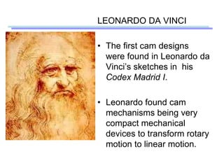
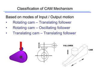
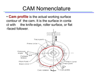
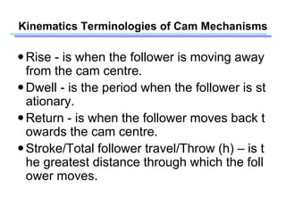
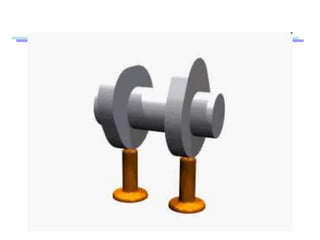
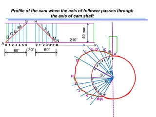
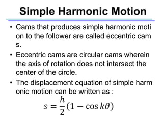
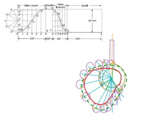
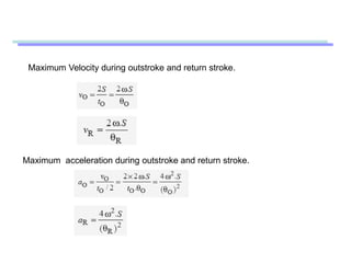
Kinematic of machine(CE 101T)
(Cam analysis)
By:
Poonam Savsani
Department of Mechanical Engineering
School of Technology
1
CAM - Definition
• A cam may be defined as a machine element
having a curved outline or a curved groove,
which, by its oscillation, rotation or reciprocating
motion, gives a predetermined specified motion
to another element called the follower .
• It is usually consists of a cam (the driver), the foll
ower (the driven element), and the frame (the su
pport for the cam and the follower).
PARTS OF CAM MECHANISM
KINEMATIC DIAGRAM FOR CAM MECHANISM
LEONARDO DA VINCI
• The first cam designs
were found in Leonardo da
Vinci’s sketches in his
Codex Madrid I.
• Leonardo found cam
mechanisms being very
compact mechanical
devices to transform rotary
motion to linear motion.
Cam hammer
Designed around
1497 by
Leonardo da Vinci
The hammer uses
a cam to convert
rotary motion to
oscillating motion.
Examples for cam
• In IC engines to operate the inlet and exhaust valves
Classification of CAM Mechanism
Based on modes of Input / Output motion
• Rotating cam – Translating follower
• Rotating cam – Oscillating follower
• Translating cam – Translating follower
Classification of followers
According to the shape of follower
• Knife edge follower
• Roller follower
• Flat faced follower
• Spherical faced follower
According to the path of motion of follower
a) Radial follower
b) Offset follower
a) Radial follower
• When the motion of the follower is along an axis p
assing through the centre of the cam, it is known a
s radial followers. Above figures are examples of t
his type.
b) Offset follower
When the motion of the follower is along an axis away from t
he axis of the cam centre, it is called off-set follower. Above f
igures are examples of this type.
• According to movement
– Reciprocating follower
– oscillating follower
Classification of cams
a) Radial or disc cam
b) Cylindrical cam
c) End cam
a) Radial or Disc cam
In radial cams, the follower reciprocates or oscillates
in a direction perpendicular to the cam axis.
b) Cylindrical cams
In cylindrical cams, the follower reciprocates
or oscillates in a direction parallel to the cams
axis.
c) End cams
It is also similar
to cylindrical cams,
but the follower
makes contact at
periphery of the
cam as shown in
fig
CAM Nomenclature
• Cam profile is the actual working surface
contour of the cam. It is the surface in conta
ct with the knife-edge, roller surface, or flat
-faced follower.
CAM Nomenclature
Base circle is the smallest circle
drawn to the cam profile from the radial
cam center. Obviously, the cam size is
dependent on the established size of
the base circle.
Trace point is the point on the follo
wer located at the knife-edge, roller ce
nter, or spherical-faced center.
TRACE POINT
CAM Nomenclature
• Pitch curve : The path
generated by the trace
point as the follower is
rotated about a stationer
y cam.
 Prime circle: The small
est circle from the cam
center through the pitch
curve
CAM Nomenclature
Pressure angle: The angle between the direction of the
follower movement and the normal to the pitch curve
PRESSURE
ANGLE
Pitch point: Pitch point corresp
onds to the point of maximum
pressure angle.
PITCH POINT
Pitch circle: A circle drawn from the cam center and p
asses through the pitch point is called Pitch circle
Stroke: The greatest distance o
r angle through which the follow
er moves or rotates
Constraints on the Follower
With external down ward force
Without external down ward force
In all cam systems it is important that the follower is always in contact a
nd following the motion of the cam.
 Gravity constraint
The weight of the follower system is sufficient to maintain contact.
 Spring constraint
The spring must be properly designed to maintain contact.
Constraints on the Follower
• Positive mechanical constraint
A groove maintains positive action.
Application of cam
• Camshaft of an Engine
• Camshaft of an Engine incorporating a Rocker
Arm
• Oil pump working
ANALYSIS OF CAM FOLLOWER MOTION
KINEMATICS OF CAM AND
FOLLOWER
Rise - is when the follower is moving away
from the cam centre.
Dwell - is the period when the follower is st
ationary.
Return - is when the follower moves back t
owards the cam centre.
Stroke/Total follower travel/Throw (h) – is t
he greatest distance through which the foll
ower moves.
Kinematics Terminologies of Cam Mechanisms
Angle of return / descent
Angle of dwell
Angle of dwell
Angle of rise / ascent / outstroke
Angle of action
• Displacement (s) – is the position of the
follower from a specific zero or rest position
in relation to time or the rotary angle of the
cam.
• Velocity (v) – is the speed with which the
cam moves the follower.
• Acceleration (a) – is the rate of change of
the follower’s velocity.
• Jerk (j) – is the rate of change of the follow
er’s acceleration.
• Angular velocity (ω) – is the speed of the c
am or the ratio of the angular displacemen
t by the cam to the time interval ∆t.
where θ is in radians
Follower Displacement Diagram
• A follower displacement diagram is a
graph showing displacement of the followe
r plotted as a function of time.
• Since the cam usually rotates at constant
angular velocity, the t-axis can be consider
as the θ-axis.
• The follower displacement diagram determ
ines the shape of the cam.
where:
h is the stroke
t is in seconds
θ is in radians
Motion of the Follower
1. Uniform motion ( constant velocity)
2. Simple harmonic motion
3. Uniform acceleration and retardation motion
4. Cycloidal motion
a) Uniform motion (constant velocity)
Displacement diagram
Since the follower moves with uniform velocity during its
rise and fall, the slope of the displacement curve must be co
nstant as shown in fig
RISE DWELL RETURN DWELL
ANGLE OF ROTATION
STROKE
ω
• Generally, this design
is not used for critical
systems because the
high acceleration at
the two ends of the
segment will result in
large forces that will
smooth out in the
cam.
• The shock effects inherent from the uniform velocity can be reduces
by modifying the motion.
• The modification is to have the follower undergoing uniform accelera
tion at the start of the constant velocity interval and uniform decelera
tion at the end of the constant velocity interval, so that the velocity c
urve is continuous.
Modified Uniform Velocity
• In constructing the cam profile, we employ
the principle of kinematic inversion, imagin
ing the cam to be stationary and allowing t
he follower to rotate opposite to the directi
on of cam rotation.
BASIC PRINCIPLE
A cam is to give the following motion to a knife-edged follower :
1. Outstroke during 60° of cam rotation ;
2. Dwell for the next 30° of cam rotation ;
3. Return stroke during next 60° of cam rotation, and
4. Dwell for the remaining 210° of cam rotation.
The stroke of the follower is 40 mm and the minimum radius of the cam is 50 mm.
The follower moves with uniform velocity during both the outstroke and return strokes.
Draw the profile of the cam when cam rotates in clockwise direction.
(a) the axis of the follower passes through the axis of the cam shaft, and
(b) the axis of the follower is offset by 20 mm from the axis of the cam shaft.
PLOT THE DISPLACEMENT DIAGRAM
40mm
60° 30° 60° 210°
A
G H
P
0 1 2 3 4 5 6 0’ 1’ 2’ 3’ 4’ 5’ 6’
B
C
D
EF J
K
L
M
N
Profile of the cam when the axis of follower passes through
the axis of cam shaft
60°
60°
30°
40mm
60° 30° 60°
A
G H
0 1 2 3 4 5 6 0’ 1’ 2’ 3’ 4’ 5’ 6’
B
C
D
EF
J
K
L
M
N
1 0
23
4
5
6
0’
1’
2’
3’
4’
5’ 6’
A
B
CDE
F
G
H
I
J
K
L M N
I
210°
the axis of the follower is offset by 20 mm from the axis
of the cam shaft.
60°
60°
30°
40mm
60° 30° 60°
A
G H
0 1 2 3 4 5 6 0’ 1’ 2’ 3’ 4’ 5’ 6’
B
C
D
EF
J
K
L
M
N
2345
6
0’
1’
2’
3’
4’
5’
6’
I
210°
A
B
CD
E
F
G
H
I
J
K
L
M
N
OFFSET CIRCLE r=20 mm
BASE CIRCLE r=50 mm
Simple Harmonic Motion
• Cams that produces simple harmonic moti
on to the follower are called eccentric cam
s.
• Eccentric cams are circular cams wherein
the axis of rotation does not intersect the
center of the circle.
• The displacement equation of simple harm
onic motion can be written as :
SIMPLE HARMONIC MOTION
Time required for the out stroke of the
follower in seconds,
tO = θO /ω
Max velocity and acceleration during
outstroke
Max velocity and acceleration during
returnstroke
87
6
5
4
3
2
1 0
s
ϴo ϴR
1 2 3 4 5 6 7 8
ϴd
A cam, with a minimum radius of 25 mm, rotating clockwise at a uniform speed
is to be designed to give a roller follower, at the end of a valve rod, motion described be
low :
1. To raise the valve through 50 mm during 120° rotation of the cam ;
2. To keep the valve fully raised through next 30°;
3. To lower the valve during next 60°; and
4. To keep the valve closed during rest of the revolution i.e. 150° ;
The diameter of the roller is 20 mm and the diameter of the cam shaft is 25 mm.
Draw the profile of the cam when
(a) the line of stroke of the valve rod passes through the axis of the cam shaft, and
(b) the line of the stroke is offset 15 mm from the axis of the cam shaft.
The displacement of the valve, while being raised and lowered, is to take plac
e with simple harmonic motion. Determine the maximum acceleration of the valve ro
d when the cam shaft rotates at 100 r.p.m. Draw the displacement, the velocity and the
acceleration diagrams for one complete revolution of the cam.
Profile of the cam when the line of stroke of the valve rod passes through
the axis of the cam shaft
6030
0
1
2
3
4
5
6
50
1 2 3 4 5 6 0’1’ 2’ 3’ 4’5 6’
120
150
A
B
C
D
E F
G H
J K
L
M
N
P
1
2
3
4
5
6
AB
C
D
E
F
G
H J
K
L
M
N
P
Profile of the cam when the line of stroke of the valve rod is offset 15 mm
from the axis of the cam shaft.
120°
30°
60°
0
12
3
4
5
6
0’
1’ 2’
3’ 4’5’ 6’
A
B
CD
E
F
G
H
J K
L
M
N P
angular velocity of the cam
Follower Moves with Uniform Acceleration and Retardation
Maximum Velocity during outstroke and return stroke.
Maximum acceleration during outstroke and return stroke.
ϴO° ϴD° ϴR° ϴD°
0 1 2 3 4 5 6 0’ 1’ 2’ 3’ 4’ 5’ 6’
0123456
0’1’2’3’4’5’6’
A
G H
N
• A cycloidal curve is the path traced by a p
oint on a circle as the circle rolls on a strai
ght line.
• To create a cycloidal motion in cam design
, involves superimposing cycloidal motion
on constant velocity motion.
• No acceleration discontinuities, therefore it
can be applied to high speeds.
Cycloidal Motion
CYCLOIDAL MOTION
Displacement equation for the cycloid motion
Maximum velocity during rise and return stroke
Maximum acceleration during rise and return stroke
Displacement dia for cycloid motion
ϴo
A
B
S = 2п r
r = S/ 2п
12
3
4 5
6
a'
b'
0’ 1’ 2’ 3’ 4’ 5’ 6’
a
b
c
d e
A cam drives a flat reciprocating follower in the following manner :
During first 120° rotation of the cam, follower moves outwards through a distance
of 20 mm with simple harmonic motion. The follower dwells during next 30° of ca
m rotation. During next 120° of cam rotation, the follower moves inwards with
simple harmonic motion. The follower dwells for the next 90° of cam rotation. The
minimum radius of the cam is 25 mm. Draw the profile of the cam.
120°
30°
120°
01
2
3
4
5
6
AB
C
D
E
F
G
H
J K
L
M
N
P
Min radius of cam=base circle radius
= 25mm
A cam drives a flat reciprocating follower in the following manner :
During first 120° rotation of the cam, follower moves outwards through a distance
of 20 mm with uniform acceleration and retardation. The follower dwells durin
g next 30° of cam rotation. During next 120° of cam rotation, the follower moves i
nwards with uniform acceleration and retardation. The follower dwells for the
next 90° of cam rotation. The minimum radius of the cam is 25 mm. Draw t
he profile of the cam.
120°
30°
120°
01
2
3
4
5
6
AB
C
D
E
F
G
H
J K
L
M
N
P
A cam drives a flat reciprocating follower in the following manner :
During first 120° rotation of the cam, follower moves outwards through a distance
of 20 mm with simple hormonic motion. The follower dwells during next 30° of
cam rotation. During next 120° of cam rotation, the follower moves inwards with
uniform acceleration and retardation. The follower dwells for the next 90° of ca
m rotation. The minimum radius of the cam is 25 mm. Draw the profile of t
he cam.
Draw a cam profile to drive an oscillating roller follower to the specifications
given below :
(a) Follower to move outwards through an angular displacement of
20° during the first 120°rotation of the cam ;
(b) Follower to return to its initial position during next 120° rotation of
the cam ;
(c) Follower to dwell during the next 120° of cam rotation.
The distance between pivot centre and roller centre = 120 mm ; distance betwe
en pivot centre and cam axis = 130 mm ; minimum radius of cam = 40 mm ; radi
us of roller = 10 mm ; inward and outward strokes take place with simple harmo
nic motion.
s
O
A
A1
120° 120°
120°
1
2
3
4
5 6
1’
2’
3’
4’
5’
6’
1
2
3
4
5
6
1’
2’ 3’ 4’
5’
6’
B
C
D
E
F
G
H
J
K
L
M
N

Cam & Profile

  • 1.
    Kinematic of machine(CE101T) (Cam analysis) By: Poonam Savsani Department of Mechanical Engineering School of Technology 1
  • 2.
    CAM - Definition •A cam may be defined as a machine element having a curved outline or a curved groove, which, by its oscillation, rotation or reciprocating motion, gives a predetermined specified motion to another element called the follower . • It is usually consists of a cam (the driver), the foll ower (the driven element), and the frame (the su pport for the cam and the follower).
  • 3.
    PARTS OF CAMMECHANISM
  • 4.
    KINEMATIC DIAGRAM FORCAM MECHANISM
  • 5.
    LEONARDO DA VINCI •The first cam designs were found in Leonardo da Vinci’s sketches in his Codex Madrid I. • Leonardo found cam mechanisms being very compact mechanical devices to transform rotary motion to linear motion.
  • 6.
    Cam hammer Designed around 1497by Leonardo da Vinci The hammer uses a cam to convert rotary motion to oscillating motion.
  • 7.
    Examples for cam •In IC engines to operate the inlet and exhaust valves
  • 8.
    Classification of CAMMechanism Based on modes of Input / Output motion • Rotating cam – Translating follower • Rotating cam – Oscillating follower • Translating cam – Translating follower
  • 9.
    Classification of followers Accordingto the shape of follower • Knife edge follower • Roller follower • Flat faced follower • Spherical faced follower
  • 10.
    According to thepath of motion of follower a) Radial follower b) Offset follower
  • 11.
    a) Radial follower •When the motion of the follower is along an axis p assing through the centre of the cam, it is known a s radial followers. Above figures are examples of t his type.
  • 12.
    b) Offset follower Whenthe motion of the follower is along an axis away from t he axis of the cam centre, it is called off-set follower. Above f igures are examples of this type.
  • 13.
    • According tomovement – Reciprocating follower – oscillating follower
  • 14.
    Classification of cams a)Radial or disc cam b) Cylindrical cam c) End cam
  • 15.
    a) Radial orDisc cam In radial cams, the follower reciprocates or oscillates in a direction perpendicular to the cam axis.
  • 16.
    b) Cylindrical cams Incylindrical cams, the follower reciprocates or oscillates in a direction parallel to the cams axis.
  • 17.
    c) End cams Itis also similar to cylindrical cams, but the follower makes contact at periphery of the cam as shown in fig
  • 18.
    CAM Nomenclature • Camprofile is the actual working surface contour of the cam. It is the surface in conta ct with the knife-edge, roller surface, or flat -faced follower.
  • 19.
    CAM Nomenclature Base circleis the smallest circle drawn to the cam profile from the radial cam center. Obviously, the cam size is dependent on the established size of the base circle. Trace point is the point on the follo wer located at the knife-edge, roller ce nter, or spherical-faced center. TRACE POINT
  • 20.
    CAM Nomenclature • Pitchcurve : The path generated by the trace point as the follower is rotated about a stationer y cam.  Prime circle: The small est circle from the cam center through the pitch curve
  • 21.
    CAM Nomenclature Pressure angle:The angle between the direction of the follower movement and the normal to the pitch curve PRESSURE ANGLE Pitch point: Pitch point corresp onds to the point of maximum pressure angle. PITCH POINT Pitch circle: A circle drawn from the cam center and p asses through the pitch point is called Pitch circle Stroke: The greatest distance o r angle through which the follow er moves or rotates
  • 22.
    Constraints on theFollower With external down ward force Without external down ward force
  • 23.
    In all camsystems it is important that the follower is always in contact a nd following the motion of the cam.  Gravity constraint The weight of the follower system is sufficient to maintain contact.  Spring constraint The spring must be properly designed to maintain contact. Constraints on the Follower • Positive mechanical constraint A groove maintains positive action.
  • 26.
    Application of cam •Camshaft of an Engine
  • 27.
    • Camshaft ofan Engine incorporating a Rocker Arm
  • 28.
    • Oil pumpworking
  • 29.
    ANALYSIS OF CAMFOLLOWER MOTION KINEMATICS OF CAM AND FOLLOWER
  • 30.
    Rise - iswhen the follower is moving away from the cam centre. Dwell - is the period when the follower is st ationary. Return - is when the follower moves back t owards the cam centre. Stroke/Total follower travel/Throw (h) – is t he greatest distance through which the foll ower moves. Kinematics Terminologies of Cam Mechanisms
  • 32.
    Angle of return/ descent Angle of dwell Angle of dwell Angle of rise / ascent / outstroke Angle of action
  • 33.
    • Displacement (s)– is the position of the follower from a specific zero or rest position in relation to time or the rotary angle of the cam. • Velocity (v) – is the speed with which the cam moves the follower. • Acceleration (a) – is the rate of change of the follower’s velocity.
  • 34.
    • Jerk (j)– is the rate of change of the follow er’s acceleration. • Angular velocity (ω) – is the speed of the c am or the ratio of the angular displacemen t by the cam to the time interval ∆t. where θ is in radians
  • 35.
    Follower Displacement Diagram •A follower displacement diagram is a graph showing displacement of the followe r plotted as a function of time. • Since the cam usually rotates at constant angular velocity, the t-axis can be consider as the θ-axis. • The follower displacement diagram determ ines the shape of the cam.
  • 36.
    where: h is thestroke t is in seconds θ is in radians
  • 37.
    Motion of theFollower 1. Uniform motion ( constant velocity) 2. Simple harmonic motion 3. Uniform acceleration and retardation motion 4. Cycloidal motion
  • 38.
    a) Uniform motion(constant velocity) Displacement diagram Since the follower moves with uniform velocity during its rise and fall, the slope of the displacement curve must be co nstant as shown in fig RISE DWELL RETURN DWELL ANGLE OF ROTATION STROKE
  • 39.
  • 40.
    • Generally, thisdesign is not used for critical systems because the high acceleration at the two ends of the segment will result in large forces that will smooth out in the cam.
  • 41.
    • The shockeffects inherent from the uniform velocity can be reduces by modifying the motion. • The modification is to have the follower undergoing uniform accelera tion at the start of the constant velocity interval and uniform decelera tion at the end of the constant velocity interval, so that the velocity c urve is continuous. Modified Uniform Velocity
  • 43.
    • In constructingthe cam profile, we employ the principle of kinematic inversion, imagin ing the cam to be stationary and allowing t he follower to rotate opposite to the directi on of cam rotation. BASIC PRINCIPLE
  • 44.
    A cam isto give the following motion to a knife-edged follower : 1. Outstroke during 60° of cam rotation ; 2. Dwell for the next 30° of cam rotation ; 3. Return stroke during next 60° of cam rotation, and 4. Dwell for the remaining 210° of cam rotation. The stroke of the follower is 40 mm and the minimum radius of the cam is 50 mm. The follower moves with uniform velocity during both the outstroke and return strokes. Draw the profile of the cam when cam rotates in clockwise direction. (a) the axis of the follower passes through the axis of the cam shaft, and (b) the axis of the follower is offset by 20 mm from the axis of the cam shaft. PLOT THE DISPLACEMENT DIAGRAM 40mm 60° 30° 60° 210° A G H P 0 1 2 3 4 5 6 0’ 1’ 2’ 3’ 4’ 5’ 6’ B C D EF J K L M N
  • 45.
    Profile of thecam when the axis of follower passes through the axis of cam shaft 60° 60° 30° 40mm 60° 30° 60° A G H 0 1 2 3 4 5 6 0’ 1’ 2’ 3’ 4’ 5’ 6’ B C D EF J K L M N 1 0 23 4 5 6 0’ 1’ 2’ 3’ 4’ 5’ 6’ A B CDE F G H I J K L M N I 210°
  • 46.
    the axis ofthe follower is offset by 20 mm from the axis of the cam shaft. 60° 60° 30° 40mm 60° 30° 60° A G H 0 1 2 3 4 5 6 0’ 1’ 2’ 3’ 4’ 5’ 6’ B C D EF J K L M N 2345 6 0’ 1’ 2’ 3’ 4’ 5’ 6’ I 210° A B CD E F G H I J K L M N OFFSET CIRCLE r=20 mm BASE CIRCLE r=50 mm
  • 47.
    Simple Harmonic Motion •Cams that produces simple harmonic moti on to the follower are called eccentric cam s. • Eccentric cams are circular cams wherein the axis of rotation does not intersect the center of the circle. • The displacement equation of simple harm onic motion can be written as :
  • 48.
  • 49.
    Time required forthe out stroke of the follower in seconds, tO = θO /ω Max velocity and acceleration during outstroke Max velocity and acceleration during returnstroke
  • 51.
  • 52.
    A cam, witha minimum radius of 25 mm, rotating clockwise at a uniform speed is to be designed to give a roller follower, at the end of a valve rod, motion described be low : 1. To raise the valve through 50 mm during 120° rotation of the cam ; 2. To keep the valve fully raised through next 30°; 3. To lower the valve during next 60°; and 4. To keep the valve closed during rest of the revolution i.e. 150° ; The diameter of the roller is 20 mm and the diameter of the cam shaft is 25 mm. Draw the profile of the cam when (a) the line of stroke of the valve rod passes through the axis of the cam shaft, and (b) the line of the stroke is offset 15 mm from the axis of the cam shaft. The displacement of the valve, while being raised and lowered, is to take plac e with simple harmonic motion. Determine the maximum acceleration of the valve ro d when the cam shaft rotates at 100 r.p.m. Draw the displacement, the velocity and the acceleration diagrams for one complete revolution of the cam.
  • 53.
    Profile of thecam when the line of stroke of the valve rod passes through the axis of the cam shaft 6030 0 1 2 3 4 5 6 50 1 2 3 4 5 6 0’1’ 2’ 3’ 4’5 6’ 120 150 A B C D E F G H J K L M N P
  • 54.
  • 55.
    Profile of thecam when the line of stroke of the valve rod is offset 15 mm from the axis of the cam shaft. 120° 30° 60° 0 12 3 4 5 6 0’ 1’ 2’ 3’ 4’5’ 6’ A B CD E F G H J K L M N P
  • 56.
  • 57.
    Follower Moves withUniform Acceleration and Retardation
  • 58.
    Maximum Velocity duringoutstroke and return stroke. Maximum acceleration during outstroke and return stroke.
  • 59.
    ϴO° ϴD° ϴR°ϴD° 0 1 2 3 4 5 6 0’ 1’ 2’ 3’ 4’ 5’ 6’ 0123456 0’1’2’3’4’5’6’ A G H N
  • 60.
    • A cycloidalcurve is the path traced by a p oint on a circle as the circle rolls on a strai ght line. • To create a cycloidal motion in cam design , involves superimposing cycloidal motion on constant velocity motion. • No acceleration discontinuities, therefore it can be applied to high speeds. Cycloidal Motion
  • 62.
  • 63.
    Displacement equation forthe cycloid motion Maximum velocity during rise and return stroke
  • 64.
    Maximum acceleration duringrise and return stroke
  • 65.
    Displacement dia forcycloid motion ϴo A B S = 2п r r = S/ 2п 12 3 4 5 6 a' b' 0’ 1’ 2’ 3’ 4’ 5’ 6’ a b c d e
  • 67.
    A cam drivesa flat reciprocating follower in the following manner : During first 120° rotation of the cam, follower moves outwards through a distance of 20 mm with simple harmonic motion. The follower dwells during next 30° of ca m rotation. During next 120° of cam rotation, the follower moves inwards with simple harmonic motion. The follower dwells for the next 90° of cam rotation. The minimum radius of the cam is 25 mm. Draw the profile of the cam.
  • 68.
  • 69.
    A cam drivesa flat reciprocating follower in the following manner : During first 120° rotation of the cam, follower moves outwards through a distance of 20 mm with uniform acceleration and retardation. The follower dwells durin g next 30° of cam rotation. During next 120° of cam rotation, the follower moves i nwards with uniform acceleration and retardation. The follower dwells for the next 90° of cam rotation. The minimum radius of the cam is 25 mm. Draw t he profile of the cam.
  • 70.
  • 71.
    A cam drivesa flat reciprocating follower in the following manner : During first 120° rotation of the cam, follower moves outwards through a distance of 20 mm with simple hormonic motion. The follower dwells during next 30° of cam rotation. During next 120° of cam rotation, the follower moves inwards with uniform acceleration and retardation. The follower dwells for the next 90° of ca m rotation. The minimum radius of the cam is 25 mm. Draw the profile of t he cam.
  • 72.
    Draw a camprofile to drive an oscillating roller follower to the specifications given below : (a) Follower to move outwards through an angular displacement of 20° during the first 120°rotation of the cam ; (b) Follower to return to its initial position during next 120° rotation of the cam ; (c) Follower to dwell during the next 120° of cam rotation. The distance between pivot centre and roller centre = 120 mm ; distance betwe en pivot centre and cam axis = 130 mm ; minimum radius of cam = 40 mm ; radi us of roller = 10 mm ; inward and outward strokes take place with simple harmo nic motion. s
  • 74.

Editor's Notes