This document summarizes the design of a reinforced concrete bridge with T-section beams. It includes the bridge dimensions, specifications for loads and materials, and calculations for the design of the bridge components. The calculations determine the required reinforcement for the piers, beams, and slabs based on bending moments and shear forces from dead and live loads. Reinforcement sizes and spacing are selected to satisfy strength and serviceability limits.
Ringkasan dokumen tersebut adalah:
1. Dokumen tersebut membahas konsep tegangan, regangan, dan lendutan pada balok. Termasuk definisi tegangan normal, geser, dan lentur serta hubungannya dengan regangan.
2. Juga dibahas cara menentukan titik berat dan momen inersia pada penampang regular dan gabungan yang digunakan untuk menghitung tegangan dan lendutan.
3. Memberikan contoh perhitungan titik berat pada penampang
Dokumen tersebut membahas perhitungan penulangan kolom beton bertulang. Terdapat persyaratan penulangan kolom seperti lindungan beton minimal, rasio luas tulangan terhadap luas penampang, jumlah dan jarak tulangan memanjang serta sengkang ikat. Diberikan contoh perhitungan penentuan penampang dan penulangan kolom untuk menahan beban tekan 1500 kN dan momen 80 kNm.
Dokumen ini berisi perhitungan struktur slab lantai jembatan di Yogyakarta. Termasuk perhitungan berat sendiri, beban tambahan, beban truk, beban angin, dan pengaruh temperatur untuk mendapatkan momen pada slab. Kemudian dilakukan pemilihan tulangan lentur positif dan negatif berdasarkan momen tersebut dengan mempertimbangkan mutu beton dan baja serta tebal slab.
Dokumen ini memberikan contoh penyelesaian masalah desain balok kantilever beton bertulang dengan beban hidup dan mati yang teraplikasi sepanjang balok. Langkah-langkah desain meliputi analisis momen lentur akibat beban, penentuan kebutuhan tulangan tarik, pemilihan diameter tulangan, dan pengecekan kapasitas penampang balok. Metode ini merupakan salah satu cara penyelesaian masalah desain balok kantilever.
Fantastic tutorial, shared with us by Dario Ilardi, of Grafica2d3d.com, I recommend to see.
The website is in Italian, but it is full of excellent tutorials, understandable in any language.
This great tutorial, explain, step by step, how to obtain, by using vray 2.0 for sketchup, a render, clear and clean as what we see in the picture below.
Dario say : " I'm experimenting with the use of brute force as a substitute of irradiance map and I must say that in terms of speed and quality impressed me positively "
Thanks so much Dario for this one, the result is really good !
The document provides calculations for determining the required reinforcement of a concrete beam (balok) with the following information:
- Concrete compressive strength is 20 MPa
- Steel yield strength is 400 MPa
- Beam dimensions are 25cm x 40cm
- Loads include wall weight, floor finish weight, and live loads from balconies
Bending moments are calculated at different points along the beam due to the varying loads. Required steel reinforcement is then determined based on the bending moment values and reinforcement ratios from code tables. Reinforcement amounts are provided for three sections of the beam labeled A-B, B-C, and C-D.
This document summarizes the planning and design calculations for a pre-stressed concrete beam with the following parameters:
1. The required bending moment (Mt) is 350 ton-meters. The concrete compressive strength (f'c) is 47 MPa.
2. The initial dimensions of the beam are calculated as 200 cm height (h) and 4339.6 cm^2 cross-sectional area (Ab).
3. The final design meets the required bending moment of 350 ton-meters with a uniform prestress force (q) of 2285.71 kg/m distributed over the beam length. Stresses in the concrete are calculated to remain below the allowable limits.
Struktur statis tak tentu metode clapeyron-portal tak bergoyangMOSES HADUN
Metode Clapeyron-Portal Tak Bergoyang memberikan syarat-syarat agar portal tidak bergoyang serta penjelasan mengenai arah momen dan lengkung pada batang mendatar dan tegak. Dokumen ini juga mendemonstrasikan penyelesaian soal struktur statis dengan metode ini, termasuk pembuatan diagram beban bebas dan superposisi momen untuk menentukan momen maksimum.
Prosedur Perencanaan Perkerasan Jalan Lentur dan Kaku wahyu nurul aini
Dokumen tersebut merangkum prosedur perencanaan perkerasan jalan raya yang mencakup penentuan umur rencana, perhitungan nilai ESA, menentukan struktur perkerasan, segmen tanah dasar, desain fondasi, drainase, dan pelapisan bahu jalan. Dokumen tersebut juga menjelaskan proses pengaspalan jalan dan memberikan alternatif perkerasan kaku berdasarkan perhitungan beban lalu lintas.
Dokumen tersebut membahas tentang struktur statis tertentu pada mekanika struktur, dimana struktur tersebut dapat diselesaikan menggunakan persamaan keseimbangan berupa jumlah gaya horizontal, vertikal dan momen yang sama dengan nol. Contoh struktur statis tertentu adalah balok diatas dua perletakan dengan jumlah reaksi yang tidak diketahui maksimal tiga. Dokumen juga menjelaskan tentang gaya-gaya dalam sepert
Laporan ini mendeskripsikan uji kuat tarik yang dilakukan terhadap dua jenis baja konstruksi, yaitu baja tulangan polos dan baja tulangan sirip. Uji ini bertujuan untuk menentukan tegangan leleh, tegangan putus, dan regangan maksimum dari masing-masing baja. Hasilnya menunjukkan bahwa baja tulangan polos memiliki tegangan leleh 319,99 MPa dan baja tulangan sirip memiliki tegangan lele
Buku ini membahas perencanaan struktur baja dengan metode Load and Resistance Factor Design (LRFD) sesuai dengan Standar Nasional Indonesia 03-1729-2002. Buku ini membahas tentang analisis dan desain berbagai komponen struktur baja seperti tekan, lentur, sambungan baut dan las, serta komposit dan sambungan untuk konstruksi bangunan gedung.
Dokumen tersebut merupakan standar nasional Indonesia tentang baja tulangan beton. Dokumen tersebut menjelaskan definisi, jenis, syarat mutu, ukuran, dan sifat mekanik yang harus dipenuhi baja tulangan beton.
Dokumen tersebut membahas tentang keseimbangan regangan pada balok beton bertulang. Terdapat tiga hal penting yaitu: 1) letak garis netral tergantung pada jumlah tulangan baja tarik, 2) keseimbangan regangan menempati posisi penting sebagai pembatas antara dua cara hancur yang berbeda, 3) standar menetapkan pembatasan jumlah penulangan agar tercapai daktilitas.
Dokumen tersebut merangkum perhitungan struktur portal gable yang mencakup perhitungan dimensi gording, kombinasi beban yang meliputi beban mati, beban hidup, beban angin dan hujan, serta kontrol tegangan dan lendutan gording untuk memastikan struktur memenuhi syarat kuat lentur dan kokoh.
1. Dokumen tersebut membahas perancangan balok beton bertulang untuk menopang beban hidup dan mati pada bentangan 7 meter.
2. Pembahasan meliputi penentuan momen lentur maksimum, luas penampang tulangan, dan ukuran balok yang memenuhi syarat tegangan.
3. Diberikan contoh soal perhitungan balok dan sketsa rencana balok untuk bentangan 7,5 meter dengan beban dan mutu material tertentu.
The document summarizes the design of batten plates connecting back-to-back channel sections in a built-up column using both bolt and weld connections. For the bolt connection, 420x340x8mm end batten plates and 420x300x8mm intermediate batten plates are designed to transmit shear and bending forces using four 20mm diameter bolts per connection. For the weld connection, 360x270x6mm end batten plates and 360x220x6mm intermediate batten plates are designed using full penetration welds on all sides to transmit the forces. Both connections are checked to verify the capacities of the bolts/welds are not exceeded.
1) Ribs are an important structural member in slabs that carry loads and transfer them to beams and columns.
2) The document provides details on the design of positive and negative reinforcement for two ribs (R1 and R2) in a slab.
3) The design includes calculating steel ratios and areas based on the ultimate moments, concrete properties, and code requirements. Reinforcement is selected to meet the calculated minimum area.
materi kuliah it pln perhitungan plat balokIlhamPutera2
The document describes the design of a two-way slab using the direct design method, with given parameters such as building data, loads, panel and column sizes. It details the calculations of slab thickness, moments, and reinforcement requirements. The slab thickness is determined to be 170mm based on stiffness requirements. Distribution of bending moments are calculated along the x- and y-directions. Reinforcement amounts are designed for slab sections at column strips and center strips based on the bending moments.
This document discusses compression testing and summarizes:
1. It describes the barrel shape of compressed specimens and types of failure under compression.
2. It outlines limitations of compression tests and precautions needed for the tests.
3. It provides information on specimen size, shape, and dimensions for different test purposes and defines terms like elastic limit stress, ultimate compressive strength, and modulus.
Gantry girder
Gantry girder or crane girder hand operated or electrically operated overhead cranes in industrial building such as factories, workshops, steel works, etc. to lift heavy materials, equipment etc. and carry them from one location to other , within the building
The GANTRY GIRDER spans between brackets attached to columns, which may either be of steel or reinforced concrete. Thus the span of gantry girder is equal to centre to centre spacing of columns. The rails are mounted on gantry girders.
Loads acting on gantry girder
Gantry girder, having no lateral support in its length (laterally unsupported) has to withstand the following loads:
1. Vertical loads from crane :
Self weight of crane girder
Hook load
Weight of crab (trolley)
2. Impact load from crane :
As the load is lifted using the crane hook and moved from one place to another, and released at the required place, an impact is felt on the gantry girder.
3. Longitudinal horizontal force (Drag force) :
This is caused due to the starting and stopping of the crane girder moving over the crane rails, as the crane girder moves longitudinally, i.e. in the direction of gantry girder.
This force is also known as braking force, or drag force.
This force is taken equal to 5% of the static wheel loads for EOT or hand operated cranes.
4. Lateral load (Surge load) :
Lateral forces are caused due to sudden starting or stopping of the crab when moving over the crane girder.
Lateral forces are also caused when the crane is dragging weights across the' floor of the shop.
Types of gantry girders
Depending upon the span and crane capacity, there can be many forms of gantry girders. Some commonly used forms are shows in fig .
Rolled steel beams with or without plates, channels or angles are normally used for spans up to 8m and for cranes up to 50kN capacity.
Plate girder are suitable up to span 6 to 10 m.
Plate girder with channels, angles, etc. can be used for spans more than 10m
Box girder are used foe spans more than 12m.
This document appears to be an exam for a Strength of Materials course, consisting of multiple choice and free response questions. It includes questions about stress and strain, shear stress and compressive stress calculations, types of beams, shear force and bending moment diagrams, assumptions in bending theory, modulus of elasticity calculations from tensile tests, shear and bending stresses, deflections of beams and shafts, and stresses in helical springs and thin cylindrical shells. The exam has two parts, with Part A containing short answer questions and Part B containing longer free response problems.
This document contains a series of engineering problems and questions related to structural analysis. It includes calculation of stresses, required reinforcement, and loads on structural members.
The first problem calculates compressive stress in a circular pole. The second determines development length and total bar length for a reinforced concrete member. The third calculates design moment for a one-way slab.
Additional problems analyze stresses and reinforcement for a footing, and loads on a bridge truss member from moving wheel loads and a uniform load. Diagrams and equations are provided.
This document summarizes the design of a circular overhead water tank with the following key details:
- The tank will be located in Panchampalli village and have a capacity of 750 cubic meters to serve a population of 1873 people.
- The tank dimensions include a 15 meter height and 12.6 meter diameter.
- The structural components including the dome, wall, ring beam, floor slab, columns, and footings will be designed using the Limit State method.
- STAAD and AutoCAD software will be used to analyze and detail the structural design. Reinforcement will be designed to resist forces from water pressure and other loads.
A possible solution to the struct-hub second design assessment. Inspired by the civic centre building 2018 involving wide slab panels of solid slab construction
10-Design of Tension Member with Bolted Connection (Steel Structural Design &...Hossam Shafiq II
1. The document describes the design of a tension member with either a bolted or welded end connection.
2. For the bolted connection, the design uses 4 bolts with 20 mm diameter to connect two 102x89x6.4 mm angles based on checking slip resistance, bolt shear, bearing and member strength requirements.
3. For the welded connection, the design uses two 88.9x63.5x7.9 mm angles connected by 60 mm longitudinal and transversal welds, checking weld and member strength. The longitudinal weld length is increased to 70 mm to satisfy block shear requirements.
This document discusses the design of steel structural connections using rivets. It provides examples of calculating forces in rivets for an eccentric load connection, determining the number and pattern of rivets needed for a truss connection, and designing welded and riveted connections between steel members and gusset plates. The examples calculate shear and bearing forces in rivets, check if connections are safe based on rivet capacities, and determine weld sizes. Design considerations include member forces, rivet patterns, weld lengths, and selecting sections that meet strength requirements.
This problem involves designing a gear drive system to meet specific power, speed, and ratio requirements.
1. The key specifications are: 15 kW power at 1200 rpm driving a compressor at 300 rpm, with a gear ratio of 4:1. The shafts are 400mm apart. The pinion is forged steel with 210 MPa allowable stress, and the gear is cast steel with 140 MPa stress.
2. A two-stage gear train layout is proposed to achieve a 9:1 ratio from an input of 960 rpm to transmit 2 kW power. The shafts are 200mm apart with coaxial input/output.
3. The solution involves calculating the module, pitch diameter, number
This document provides examples of calculations related to rigid pavement design, including:
1) Calculating the spacing between contraction joints for plain and reinforced concrete slabs of varying thickness and reinforcement.
2) Computing the radius of relative stiffness for concrete slabs over subgrade, given slab properties and subgrade modulus.
3) Determining wheel load stresses, dowel bar sizing and spacing, equivalent resisting section radius, and contraction joint tensile stress.
4) Summarizing the process for designing a rigid pavement using Westergaard wheel load and wrapping stress equations at the slab edge.
This document discusses reinforced concrete columns. It defines different types of columns including tied, spiral, composite, and steel pipe columns. It describes the behavior and analysis of axially loaded columns, including elastic behavior, creep effects, and nominal capacity. Design provisions from the ACI code are presented for reinforcement requirements of tied and spiral columns. The behavior of columns under combined bending and axial loads is discussed, including interaction diagrams. Examples are provided to demonstrate the design of columns for various load cases.
This document summarizes the design of a reinforced concrete flat slab for an office building. Key details include:
- The slab is 300mm thick with C30/37 concrete and required to have a 2 hour fire rating.
- The design load combinations are 1.25 times permanent load and 1.5 times imposed load.
- Moments and shear are calculated for interior and edge panels. Reinforcement amounts and bar sizes are designed to resist bending and shear using code specified equations.
- Minimum reinforcement requirements and placement details are also specified.
This document provides design details for the reinforcement of a 300mm thick flat slab with 4.5m spacing between columns. The slab is for an office with a specified imposed load of 1kN/m2 for finishes and 4kN/m2 imposed. Perimeter load is assumed to be 10kN/m. Concrete strength is C30/37. Analysis and design is carried out for grid line C, which is considered as a 6m wide bay. Reinforcement requirements are calculated for flexure, deflection, punching shear, and transfer of moments to columns. Reinforcement arrangements are proposed to meet the calculated requirements.
1. The document contains 7 engineering problems related to calculating the load capacity of columns using Euler's theory and Rankine's formula.
2. Problem 1 compares the strength ratio of a solid steel column to a hollow steel column of the same cross-sectional area.
3. Problem 2 calculates the safe compressive load for a solid round bar strut with different end conditions using Euler's formula.
Numericals on Columns and struts_-_solvedViriSharma
This document contains 7 problems related to calculating the load capacity of steel columns using Euler's theory and Rankine's formula. Problem 1 compares the strength ratio of a solid vs hollow steel column. Problem 2 calculates the safe load for a solid round bar column with different end conditions. Problem 3 finds the strength ratio of a solid vs hollow steel column with the same cross-sectional area. Problem 4 calculates the Euler crushing load and compares it to Rankine's formula. Problems 5-7 involve calculating column load capacities for various steel sections using Euler, Rankine, and IS code methods.
1. This document discusses trial sizing, design, and analysis of short columns under concentric axial loads.
2. The criteria for determining if a column is considered short is based on the slenderness ratio being less than a specified value depending on the column cross section shape.
3. A design example is provided for a 4m long square tied column and circular spiral column both carrying an axial load of 2000 kN. The design includes calculating reinforcement, checking reinforcement ratio, and detailing requirements.
KuberTENes Birthday Bash Guadalajara - K8sGPT first impressionsVictor Morales
K8sGPT is a tool that analyzes and diagnoses Kubernetes clusters. This presentation was used to share the requirements and dependencies to deploy K8sGPT in a local environment.
Understanding Inductive Bias in Machine LearningSUTEJAS
This presentation explores the concept of inductive bias in machine learning. It explains how algorithms come with built-in assumptions and preferences that guide the learning process. You'll learn about the different types of inductive bias and how they can impact the performance and generalizability of machine learning models.
The presentation also covers the positive and negative aspects of inductive bias, along with strategies for mitigating potential drawbacks. We'll explore examples of how bias manifests in algorithms like neural networks and decision trees.
By understanding inductive bias, you can gain valuable insights into how machine learning models work and make informed decisions when building and deploying them.
6th International Conference on Machine Learning & Applications (CMLA 2024)ClaraZara1
6th International Conference on Machine Learning & Applications (CMLA 2024) will provide an excellent international forum for sharing knowledge and results in theory, methodology and applications of on Machine Learning & Applications.
A SYSTEMATIC RISK ASSESSMENT APPROACH FOR SECURING THE SMART IRRIGATION SYSTEMSIJNSA Journal
The smart irrigation system represents an innovative approach to optimize water usage in agricultural and landscaping practices. The integration of cutting-edge technologies, including sensors, actuators, and data analysis, empowers this system to provide accurate monitoring and control of irrigation processes by leveraging real-time environmental conditions. The main objective of a smart irrigation system is to optimize water efficiency, minimize expenses, and foster the adoption of sustainable water management methods. This paper conducts a systematic risk assessment by exploring the key components/assets and their functionalities in the smart irrigation system. The crucial role of sensors in gathering data on soil moisture, weather patterns, and plant well-being is emphasized in this system. These sensors enable intelligent decision-making in irrigation scheduling and water distribution, leading to enhanced water efficiency and sustainable water management practices. Actuators enable automated control of irrigation devices, ensuring precise and targeted water delivery to plants. Additionally, the paper addresses the potential threat and vulnerabilities associated with smart irrigation systems. It discusses limitations of the system, such as power constraints and computational capabilities, and calculates the potential security risks. The paper suggests possible risk treatment methods for effective secure system operation. In conclusion, the paper emphasizes the significant benefits of implementing smart irrigation systems, including improved water conservation, increased crop yield, and reduced environmental impact. Additionally, based on the security analysis conducted, the paper recommends the implementation of countermeasures and security approaches to address vulnerabilities and ensure the integrity and reliability of the system. By incorporating these measures, smart irrigation technology can revolutionize water management practices in agriculture, promoting sustainability, resource efficiency, and safeguarding against potential security threats.
ACEP Magazine edition 4th launched on 05.06.2024Rahul
This document provides information about the third edition of the magazine "Sthapatya" published by the Association of Civil Engineers (Practicing) Aurangabad. It includes messages from current and past presidents of ACEP, memories and photos from past ACEP events, information on life time achievement awards given by ACEP, and a technical article on concrete maintenance, repairs and strengthening. The document highlights activities of ACEP and provides a technical educational article for members.
CHINA’S GEO-ECONOMIC OUTREACH IN CENTRAL ASIAN COUNTRIES AND FUTURE PROSPECTjpsjournal1
The rivalry between prominent international actors for dominance over Central Asia's hydrocarbon
reserves and the ancient silk trade route, along with China's diplomatic endeavours in the area, has been
referred to as the "New Great Game." This research centres on the power struggle, considering
geopolitical, geostrategic, and geoeconomic variables. Topics including trade, political hegemony, oil
politics, and conventional and nontraditional security are all explored and explained by the researcher.
Using Mackinder's Heartland, Spykman Rimland, and Hegemonic Stability theories, examines China's role
in Central Asia. This study adheres to the empirical epistemological method and has taken care of
objectivity. This study analyze primary and secondary research documents critically to elaborate role of
china’s geo economic outreach in central Asian countries and its future prospect. China is thriving in trade,
pipeline politics, and winning states, according to this study, thanks to important instruments like the
Shanghai Cooperation Organisation and the Belt and Road Economic Initiative. According to this study,
China is seeing significant success in commerce, pipeline politics, and gaining influence on other
governments. This success may be attributed to the effective utilisation of key tools such as the Shanghai
Cooperation Organisation and the Belt and Road Economic Initiative.
CHINA’S GEO-ECONOMIC OUTREACH IN CENTRAL ASIAN COUNTRIES AND FUTURE PROSPECT
131445983 jembatan-balok-t
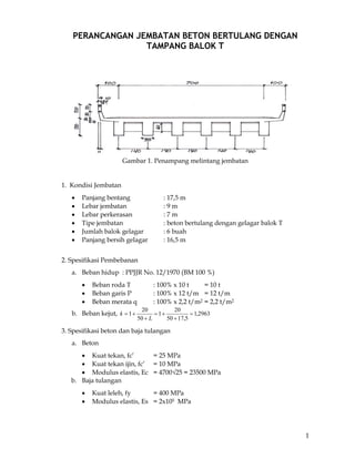
1. 1
PERANCANGAN JEMBATAN BETON BERTULANG DENGAN
TAMPANG BALOK T
Gambar 1. Penampang melintang jembatan
1. Kondisi Jembatan
• Panjang bentang : 17,5 m
• Lebar jembatan : 9 m
• Lebar perkerasan : 7 m
• Tipe jembatan : beton bertulang dengan gelagar balok T
• Jumlah balok gelagar : 6 buah
• Panjang bersih gelagar : 16,5 m
2. Spesifikasi Pembebanan
a. Beban hidup : PPJJR No. 12/1970 (BM 100 %)
• Beban roda T : 100% x 10 t = 10 t
• Beban garis P : 100% x 12 t/m = 12 t/m
• Beban merata q : 100% x 2,2 t/m2 = 2,2 t/m2
b. Beban kejut, 2963,1
5,1750
20
1
50
20
1 =
+
+=
+
+=
L
k
3. Spesifikasi beton dan baja tulangan
a. Beton
• Kuat tekan, fc’ = 25 MPa
• Kuat tekan ijin, fc’ = 10 MPa
• Modulus elastis, Ec = 4700√25 = 23500 MPa
b. Baja tulangan
• Kuat leleh, fy = 400 MPa
• Modulus elastis, Es = 2x10⁵ MPa
2. 2
PERANCANGAN
1. Tiang sandaran
momen lentur, Mu = 1,2×2×100×1,0 = 240 kg-m = 2400 N-m
gaya geser, V = 1,2 × 2 × 100 = 240 kg = 2400 N
Mn = φ bd2k
Mu = Mn
1095,1
1301608,0
102400
2
3
2
=
××
×
=
××
=
db
M
k u
φ
Mpa
3
'
'
108502,2
2585,0
1095,12
11
400
25
85,0
85,0
2
1185,0 −
×=⎟
⎟
⎠
⎞
⎜
⎜
⎝
⎛
×
×
−−=
⎟
⎟
⎠
⎞
⎜
⎜
⎝
⎛
−−=
cy
c
perlu
f
k
f
f
ρ
3
min 105,3
400
4,14,1 −
×===
yf
ρ
As = ρ x b x d = 3,5×10-3 ×160×130 = 72,8 mm2
Dipakai tulangan 2∅10 (As = 157,0796 mm2)
Kontrol kapasitas momen balok
Dianggap baja tulangan telah luluh pada saat beton mulai retak (εc = 0,003)
5,18
1602585,0
4000796,157
85,0 '
=
××
×
=
××
×
=
bf
fA
a
c
ys
mm
7647,21
85,0
5,18
1
===
β
a
c mm
7847,2983
7647,21
7647,21130
600600 =⎟
⎠
⎞
⎜
⎝
⎛ −
=⎟
⎠
⎞
⎜
⎝
⎛ −
=
c
cd
fs MPa > fy O K
68,7586944
2
5,18
1304000796,157
2
=⎟
⎠
⎞
⎜
⎝
⎛
−×=⎟
⎠
⎞
⎜
⎝
⎛
−×=
a
dfAM ysn N-mm
=7586,9447 N-m > Mu (2400 N-m) O K
Perencanaan tulangan geser
Vu = 2400 N
3333,1733313016020
6
1
6
1 '
=××=××= dbfV cc N
9999,51993333,173336,0
2
1
2
1
=××=cVφ N > Vu (secara teoritis tidak perlu sengkang)
b=160 mm
h=160 mm d=130 mm
3. 3
walaupun secara teoritis tidak perlu sengkang, tetapi untuk kestabilan struktur dan
peraturan mensyaratkan dipasang tulangan minimum
smaksimum = ½ d = ½ x 130 = 65 mm
luas tulangan geser minimum
3333,43
400
6516025
3
1
3
1 '
min =
××
=
××
=
y
c
v
f
sbf
A mm2
dipakai tulangan ∅8 (As = 100,5310 mm2), maka jarak sengkang
7965,150
16025
3
1
4005310,100
3
1 '
=
×
×
=
×
×
=
bf
fA
s
c
yv
mm
untuk penulangan geser dipakai sengkang ∅8-100
2. Perhitungan plat kantilever
Gambar 2. Pembebanan pada plat kantilever
a. momen lentur (bending moment)
Perhitungan momen lentur
No. Volume (m3) γ
(kg/m3)
W
(kg)
Lengan
(m)
Momen
(kg-m)
1 0,10 × 0,16 × 0,50 = 0,008 2400 19,2 1,8 34,5600
2 0,10×(0,70×0,110)/2 = 0,00385 2400 9,24 1,04 9,6096
3 0,10×0,05×0,50 = 0,0025 2400 6 1,025 6,1500
4 0,10 × (0,15 × 0,50)/2 = 0,00375 2400 9 0,95 8,5500
5 1,00 × 1,00 × 0,20 = 0,2 2400 480 0,5 240,0000
6 1,00 × (1,00 × 0,10)/2 = 0,05 2400 120 0,33 39,6000
7 1,00 × 0,90 × 0,07 = 0,063 2200 138,6 0,375 51,9750
P 2,0 × 100 kg/m 200 1,2 240,0000
4. 4
T 1,2963 × 10000 12963 0,5 6481,5000
Air hujan = 2 × 0,90 × 0,05 = 0,0625 1000 62,5 0,375 23,4375
Railing = 2 × 2m× 6 kg/m = 24 24 1,08 25,9200
Total momen, M 7161,3021
Total momen, M (N-m) 71613,0210
b. Gaya geser (shear force)
Berat tiang sandaran = 1 + 2 + 3 +4 + railing = 67,4400 Kg
Slab kantilever dan perkerasan = 5 + 6 +7 = 738,6000 Kg
Beban roda = 12963,0000 Kg
Beban genangan air hujan = 62,5000 Kg
Toal gaya lintang = 13831,5400 Kg
= 138315,4000 N
c. perhitungan baja tulangan
Mu = 1,2×71613,021 =85935,6252 N-m
Vu = 1,2×138315,400 = 165978,48 N
h = 300 mm d = 300-40 = 260 mm
5890,1
26010008,0
1085935,6252
2
3
2
=
××
×
=
××
=
db
M
k u
φ
MPa
027094,0
200000
400
003,0
003,0
400
85,025
85,0
003,0
003,0
85,0 1
'
=
+
×
×
=
+
×
×
=
s
yy
c
b
E
ff
f β
ρ
ρmaks = 0,75 ρb = 0,75 x 0,027094 = 0,0203205
3
'
'
101333,4
2585,0
5890,12
11
400
25
85,0
85,0
2
1185,0 −
×=⎟
⎟
⎠
⎞
⎜
⎜
⎝
⎛
×
×
−−=
⎟
⎟
⎠
⎞
⎜
⎜
⎝
⎛
−−=
cy
c
perlu
f
k
f
f
ρ
3
min 105,3
400
4,14,1 −
×===
yf
ρ
As = ρ x b x d = 4,1333x10-3 x 1000 x 260 = 1074,658 mm2
Dipakai tulangan ∅16 (As = 210,0619 mm2), dengan jarak antar tulangan
4686,195
658,1074
10000619,210
=
×
=perlus mm
dipakai tulangan ∅16-125 mm
kontrol terhadap geser beton
7296,0
2601000
165978,48
8
7
8
7
=
××
=
××
=
hb
V
cτ MPa < 0,45 fc = 11,25 MPa O K
5. 5
3. Perhitungan plat bagian dalam (inner slab)
a. Momen lentur akibat beban hidup
Gambar 3. posisi roda
Penyebaran beban hidup (roda) pada slab
P
20cm21 21
6cm
15cm
15cm
50cm21 21
P
Gambar 4. Penyebaran beban hidup pada slab
lx = 1,4 m
ly = ∞
tx = 0,92 m
ty =0,62 m
6. 6
Beban roda, T = 10000 kg
Bidang kontak = 0,92 m × 0,62 m
Penyebaran beban roda, 1571,22726
62,092,0
2963,110000
=
×
×
=T kg/m2
Dipakai tabel-Bittner (dari Dr. Ing Ernst Bittner)
Dengan lx = 1,4 , ly = ∞ (lantai tidak menumpu pada diafragma)
657,0
4,1
92,0
==
x
x
l
t
fxm = 0,1233
443,0
4,1
62,0
==
x
y
l
t
fym = 0,0661
Mxm = 0,1233 × 22726,1571 × 0,92 × 0,62 = 1598,3379 kgm = 15983,379 Nm
Mym = 0,0661 × 22726,1571 × 0,92 × 0,62 = 856,8543 kgm = 8568,543 Nm
b. momen lentur akibat beban mati
Berat slab = 0,30 × 2400 = 720 kg/m2
Berat perkerasan = 0,06 × 2200 = 132 kg/m2
Berat air hujan = 0,05 × 1000 = 50 kg/m2
Total qDL = 902 kg/m2
7920,1764,1902
10
1
10
1 22
=××=××= xDLxm lqM kgm = 1767,920 Nm
9307,587920,176
3
1
3
1
=×=×= xmym MM kgm = 589,307 Nm
c. momen total
Mx = 15983,379 + 1767,920 = 17661,299 Nm
My =8568,543 + 589,307 = 9157,85 Nm
d. perhitungan baja tulangan
arah melintang lx
M = 17661,299 Nm
h = 300 mm d = 300-40 = 260 mm
3267,0
26010008,0
1017661,299
2
3
2
=
××
×
=
××
=
db
M
k
φ
MPa
027094,0
200000
400
003,0
003,0
400
85,025
85,0
003,0
003,0
85,0 1
'
=
+
×
×
=
+
×
×
=
s
yy
c
b
E
ff
f β
ρ
ρmaks = 0,75 ρb = 0,75 x 0,027094 = 0,0203205
7. 7
4
'
'
102313,8
2585,0
3267,02
11
400
25
85,0
85,0
2
1185,0 −
×=⎟
⎟
⎠
⎞
⎜
⎜
⎝
⎛
×
×
−−=
⎟
⎟
⎠
⎞
⎜
⎜
⎝
⎛
−−=
cy
c
perlu
f
k
f
f
ρ
3
min 105,3
400
4,14,1 −
×===
yf
ρ
As = ρ x b x d = 3,5 x10-3 x 1000 x 260 = 910 mm2
Dipakai tulangan ∅16 (As = 210,0619 mm2), dengan jarak antar tulangan
8373,230
910
10000619,210
=
×
=perlus mm
dipakai tulangan ∅16-125 mm
arah memanjang ly
M = 9157,85 Nm
h = 300 mm d = 300-40 = 260 mm
1693,0
26010008,0
109157,85
2
3
2
=
××
×
=
××
=
db
M
k
φ
MPa
027094,0
200000
400
003,0
003,0
400
85,025
85,0
003,0
003,0
85,0 1
'
=
+
×
×
=
+
×
×
=
s
yy
c
b
E
ff
f β
ρ
ρmaks = 0,75 ρb = 0,75 x 0,027094 = 0,0203205
4
'
'
102495,4
2585,0
1693,02
11
400
25
85,0
85,0
2
1185,0 −
×=⎟
⎟
⎠
⎞
⎜
⎜
⎝
⎛
×
×
−−=
⎟
⎟
⎠
⎞
⎜
⎜
⎝
⎛
−−=
cy
c
perlu
f
k
f
f
ρ
3
min 105,3
400
4,14,1 −
×===
yf
ρ
As = ρ x b x d = 3,5 x10-3 x 1000 x 260 = 910 mm2
Dipakai tulangan ∅16 (As = 210,0619 mm2), dengan jarak antar tulangan
8373,230
910
10000619,210
=
×
=perlus mm
dipakai tulangan ∅16-125 mm
4. Perhitungan Gelagar
a. beban mati (dead load)
Hand rail = {(0,10 × 0,16 × 1,00 × 2400)/2} × 1,1871 = 22,7923 kg/m
Railing = 2 × 1,00 × 6 × 1,1871 = 14,2452 kg/m
Perkerasan = 0,06 × 2200 × 4,5716 = 603,4512 kg/m
Air hujan = 0,05 × 1000 × 4,5716 = 228,5800 kg/m
Pelat lantai = 0,30 × 2400 × 4,5716 = 3291,5520 kg/m
8. 8
Gelagar = 1,00 × 0,50 × 2400 × 1,00 = 1200,0000 kg/m
Total = 5360,6207 kg/m
Balok melintang (diafragma), Tb = 0,30 × 0,60 × 2400 × 0,9 = 388,8 kg
Gambar 5. Garis pengaruh momen
Gambar 6. Potongan memanjang balok pada perhitungan momen lentur
b. momen lentur akibat beban mati
⎭
⎬
⎫
⎩
⎨
⎧
⎟
⎠
⎞
⎜
⎝
⎛
−×=→
L
x
L
x
LqMM DLxqDL 1
2
1 2
Momen pada potongan 1, x = 2,0 m (M1 DL)
⎭
⎬
⎫
⎩
⎨
⎧
⎟
⎠
⎞
⎜
⎝
⎛
−××=
5,16
2
1
5,16
2
5,166207,5360
2
1 2
qDLM = 77729,0002 kgm
MTb= ½ × 388,8 × 2 = 388,8000 kgm
M1 DL = 78117,8002 kgm
781178,0020 Nm
9. 9
Momen pada potongan 2, x = 4,0 m (M2 DL)
⎭
⎬
⎫
⎩
⎨
⎧
⎟
⎠
⎞
⎜
⎝
⎛
−××=
5,16
4
1
5,16
4
5,166207,5360
2
1 2
qDLM = 134015,5175 kgm
MTb= ½ × 388,8 × 4 = 777,6000 kgm
M2 DL = 134793,1175 kgm
1347931,1750 Nm
Momen pada potongan 3, x = 6,0 m (M3 DL)
⎭
⎬
⎫
⎩
⎨
⎧
⎟
⎠
⎞
⎜
⎝
⎛
−××=
5,16
6
1
5,16
6
5,166207,5360
2
1 2
qDLM = 168859,5521 kgm
MTb= ½ × 388,8 × 6 = 1166,4000 kgm
M3 DL 170025,9521 kgm
1700259,5210 Nm
Momen pada potongan 4, x = 8,25 m (M4 DL)
⎭
⎬
⎫
⎩
⎨
⎧
⎟
⎠
⎞
⎜
⎝
⎛
−××=
5,16
25,8
1
5,16
25,8
5,166207,5360
2
1 2
qDLM = 182428,6232 kgm
MTb= ½ × 388,8 × 8,25 = 1603,8000 kgm
M4 DL 184032,4232 kgm
1840324,2320 Nm
c. Beban hidup (live load)
koefisien kejut = 1,2963
beban garis, 6294,258595716,4
75,2
12000
2963,1 =××=P kg
beban terbagi merata, 28,36575716,4
75,2
2200
=×=q kg/m
d. Momen lentur akibat beban hidup
( )
⎭
⎬
⎫
⎩
⎨
⎧
⎟
⎠
⎞
⎜
⎝
⎛
−×=
L
x
L
x
LPPM x 1
( )
⎭
⎬
⎫
⎩
⎨
⎧
⎟
⎠
⎞
⎜
⎝
⎛
−×=
L
x
L
x
LqqM x 1
2
1 2
Momen pada potongan 1, x = 2,0 m (M1 LL)
( )
⎭
⎬
⎫
⎩
⎨
⎧
⎟
⎠
⎞
⎜
⎝
⎛
−×=
5,16
2
1
5,16
2
5,166294,25859PM x = 45450,2577 kgm
( )
⎭
⎬
⎫
⎩
⎨
⎧
⎟
⎠
⎞
⎜
⎝
⎛
−××=
5,16
2
1
5,16
2
5,1628,3657
2
1 2
qM x = 53030,5600 kgm
M1 LL = 98480,8177 kgm
984808,1770 Nm
10. 10
Momen pada potongan 2, x = 4,0 m (M2 LL)
( )
⎭
⎬
⎫
⎩
⎨
⎧
⎟
⎠
⎞
⎜
⎝
⎛
−×=
5,16
4
1
5,16
4
5,166294,25859PM x = 78362,5133 kgm
( )
⎭
⎬
⎫
⎩
⎨
⎧
⎟
⎠
⎞
⎜
⎝
⎛
−××=
5,16
4
1
5,16
4
5,1628,3657
2
1 2
qM x = 91432,0000 kgm
M2 LL = 169794,5133 kgm
1697945,1330 Nm
Momen pada potongan 3, x = 6,0 m (M3 LL)
( )
⎭
⎬
⎫
⎩
⎨
⎧
⎟
⎠
⎞
⎜
⎝
⎛
−×=
5,16
6
1
5,16
6
5,166294,25859PM x = 98736,7668 kgm
( )
⎭
⎬
⎫
⎩
⎨
⎧
⎟
⎠
⎞
⎜
⎝
⎛
−××=
5,16
6
1
5,16
6
5,1628,3657
2
1 2
qM x = 115204,3200 kgm
M3 LL 213941,0868 kgm
2139410,8680 Nm
Momen pada potongan 4, x = 8,25 m (M4 LL)
( )
⎭
⎬
⎫
⎩
⎨
⎧
⎟
⎠
⎞
⎜
⎝
⎛
−×=
5,16
25,8
1
5,16
25,8
5,166294,25859PM x = 106670,9713 kgm
( )
⎭
⎬
⎫
⎩
⎨
⎧
⎟
⎠
⎞
⎜
⎝
⎛
−××=
5,16
25,8
1
5,16
25,8
5,1628,3657
2
1 2
qM x = 124461,8100 kgm
M4 LL 231132,7813 kgm
2311327,8130 Nm
Tabel. Momen lentur total
Pembebanan M.1 M.2 M.3 M.4
Beban mati, DL
Beban hidup, LL
781178,0020
984808,1770
1347931,1750
1697945,1330
1700259,5210
2139410,8680
1840324,2320
2311327,8130
Total, Mu
(1,2MD+1,6ML) 2513106,6856 4334229,6228 5463368,8140 5906513,5792
e. Gaya geser (shearing force)
Beban mati terbagi merata = 0,5 × 5360,6207 × 16,5 44225,1208 kg
Balok melintang = 1,4 × 388,8 544,3200 kg
Beban hidup garis P = 0,5 × 6294,25859 12928,8147 kg
Beban hidup terbagi merata q = 0,5 × 28,3657 × 16,5 30172,5600 kg
Total V 87870,8155 kg
878708,1550 N
11. 11
f. Perhitungan baja tulangan
Pada tumpuan
V = 878708,1550 N h = 1300 mm
b = 500 mm d = 1300 - 60 = 1240 mm
Perencanaan tulangan geser
Vu = 878708,1550 N
6667,5072911217,550025
6
1
6
1 '
=××=××= dbfV cc N
5,1521876667,5072916,0
2
1
2
1
=××=cVφ N < Vu (perlu sengkang)
Gambar 7. Diagram gaya geser (SFD)
Hasil perhitungan dapat dilihat pada tabel berikut
No. Penampang titik 1 titik 2 titik 3 titik 4
kritis 0 - 2 m 2 - 4 m 4 - 6 m 6 - 8,25 m
1 Vu (N) 878708.1550 698350.141 517992.127 337089.793
2 Vc (N) 507291.6667 507291.6667 507291.6667 507291.6667
3 ½ φ Vc (N) 152187.5 152187.5 152187.5 152187.5
Perlu sengkang Perlu sengkang Perlu sengkang Perlu sengkang
4 Vs (N) 957221.925 656625.235 356028.545 54524.655
5 s (mm) 79.91645314 116.5014334 214.8641793 1402.994317
6 s mak (mm) 608.75 608.75 608.75 608.75
7 Dipakai D10 - 75 D10 - 110 D10 - 200 D10 - 500
Potongan I-I (8,25 m dari tumpuan)
lebar efektif, diambil nilai terkecil dari :
375,45,174
1
4
1
=×== LbE m
( ) 53003001650016 =×+=+= fwE hbb mm
1400== gelagarjarakbE mm
CL
878708,1550
698350.141 517992.127
517447.807
337089.793
111642.2755
bw = 500 mm
bE = 1400 mm
hf = 300 mm
h = 1300 mm
12. 12
Mu = 5906513,5792 N-m
s
yb
b
E
fd
c
+
=
003,0
003,0
b
s
y
b d
E
f
a
+
=
003,0
003,0
85,0
ab = 0,6 db = 0,6 (1300-40) = 756 mm > 300 mm
dalam keadaan setimbang (ΣH = 0)
( ){ }tbbbaffA wfwbcyb ×−+×××=× '
85,0
( ){ } ( ){ } 34425
400
30050014005007562585,085,0 '
=
×−+×××
=
×−+×××
=
y
wfwbc
b
f
tbbbaf
A mm2
kemampuan sayap mendukung momen
9906750000
2
300
12602585,03001400
2
85,0 '
=
⎭
⎬
⎫
⎩
⎨
⎧
−××××=
⎭
⎬
⎫
⎩
⎨
⎧
−××××=
t
dftbM cf Nmm
M = 9906750 Nm > 5906513,5792 Nm → blok beton a ada di dalam sayap
Letak garis netral, c
⎭
⎬
⎫
⎩
⎨
⎧
−××××=
2
85,0 ' a
dfabM cf
⎭
⎬
⎫
⎩
⎨
⎧
−××××=
2
12602585,01400,25906513579
a
a
a2 – 2520a + 397076,5431 = 0
a = 168,8889 mm, c = 168,8889/0,85 = 198,6928 mm
luas tulangan yang diperlukan
1114,4486
400
8889,1685002585,085,0 '
=
×××
=
×××
=
y
wc
f
abf
A mm2 < 0,75×Ab = 0,75×34425
Dipakai tulangan ∅30 (As = 706,8583 mm2), jumlah tulangan yang dibutuhkan
3,6
8583,706
1114,4486
==n dipakai 8∅30 (As = 5654,8664 mm2)
Potongan II-II (6 m dari tumpuan)
Mu = 5463368,8140 N-m
s
yb
b
E
fd
c
+
=
003,0
003,0
b
s
y
b d
E
f
a
+
=
003,0
003,0
85,0
ab = 0,6 db = 0,6 (1300-40) = 756 mm > 300 mm
13. 13
dalam keadaan setimbang (ΣH = 0)
( ){ }tbbbaffA wfwbcyb ×−+×××=× '
85,0
( ){ } ( ){ } 34425
400
30050014005007562585,085,0 '
=
×−+×××
=
×−+×××
=
y
wfwbc
b
f
tbbbaf
A mm2
kemampuan sayap mendukung momen
9906750000
2
300
12602585,03001400
2
85,0 '
=
⎭
⎬
⎫
⎩
⎨
⎧
−××××=
⎭
⎬
⎫
⎩
⎨
⎧
−××××=
t
dftbM cf Nmm
M = 9906750 Nm > 5463368,8140 Nm → blok beton a ada di dalam sayap
Letak garis netral, c
⎭
⎬
⎫
⎩
⎨
⎧
−××××=
2
85,0 ' a
dfabM cf
⎭
⎬
⎫
⎩
⎨
⎧
−××××=
2
12602585,01400,05463368814
a
a
a2 – 2520a + 367285,2984 = 0
a = 155,3214 mm, c = 155,3214/0,85 = 182,7311 mm
luas tulangan yang diperlukan
7247,4125
400
155,32145002585,085,0 '
=
×××
=
×××
=
y
wc
f
abf
A mm2 < 0,75×Ab = 0,75×34425
Dipakai tulangan ∅30 (As = 706,8583 mm2), jumlah tulangan yang dibutuhkan
8,5
8583,706
7247,4125
==n dipakai 6∅30 (As = 4241,1501 mm2)
Potongan III-III (4 m dari tumpuan)
Mu = 4334229,6228 N-m
s
yb
b
E
fd
c
+
=
003,0
003,0
b
s
y
b d
E
f
a
+
=
003,0
003,0
85,0
ab = 0,6 db = 0,6 (1300-40) = 756 mm > 300 mm
dalam keadaan setimbang (ΣH = 0)
( ){ }tbbbaffA wfwbcyb ×−+×××=× '
85,0
( ){ } ( ){ } 34425
400
30050014005007562585,085,0 '
=
×−+×××
=
×−+×××
=
y
wfwbc
b
f
tbbbaf
A mm2
14. 14
kemampuan sayap mendukung momen
9906750000
2
300
12602585,03001400
2
85,0 '
=
⎭
⎬
⎫
⎩
⎨
⎧
−××××=
⎭
⎬
⎫
⎩
⎨
⎧
−××××=
t
dftbM cf Nmm
M = 9906750 Nm > 4334229,6228 Nm → blok beton a ada di dalam sayap
Letak garis netral, c
⎭
⎬
⎫
⎩
⎨
⎧
−××××=
2
85,0 ' a
dfabM cf
⎭
⎬
⎫
⎩
⎨
⎧
−××××=
2
12602585,01400,84334229622
a
a
a2 – 2520a + 291376,7813 = 0
a = 121,4820 mm, c = 121,4820/0,85 = 142,92 mm
luas tulangan yang diperlukan
8656,3226
400
121,48205002585,085,0 '
=
×××
=
×××
=
y
wc
f
abf
A mm2 < 0,75×Ab = 0,75×34425
Dipakai tulangan ∅30 (As = 706,8583 mm2), jumlah tulangan yang dibutuhkan
6,4
8583,706
8656,3226
==n dipakai 6∅30 (As = 4241,1501 mm2)
Potongan IV- IV (2 m dari tumpuan)
Mu = 2513106,6856 N-m
s
yb
b
E
fd
c
+
=
003,0
003,0
b
s
y
b d
E
f
a
+
=
003,0
003,0
85,0
ab = 0,6 db = 0,6 (1300-40) = 756 mm > 300 mm
dalam keadaan setimbang (ΣH = 0)
( ){ }tbbbaffA wfwbcyb ×−+×××=× '
85,0
( ){ } ( ){ } 34425
400
30050014005007562585,085,0 '
=
×−+×××
=
×−+×××
=
y
wfwbc
b
f
tbbbaf
A mm2
kemampuan sayap mendukung momen
9906750000
2
300
12602585,03001400
2
85,0 '
=
⎭
⎬
⎫
⎩
⎨
⎧
−××××=
⎭
⎬
⎫
⎩
⎨
⎧
−××××=
t
dftbM cf Nmm
M = 9906750 Nm > 2513106,6856 Nm → blok beton a ada di dalam sayap
15. 15
Letak garis netral, c
⎭
⎬
⎫
⎩
⎨
⎧
−××××=
2
85,0 ' a
dfabM cf
⎭
⎬
⎫
⎩
⎨
⎧
−××××=
2
12602585,01400,62513106685
a
a
a2 – 2520a + 168948,3486 = 0
a = 68,9284 mm, c = 68,9284/0,85 = 81,0922 mm
luas tulangan yang diperlukan
9106,1830
400
68,92845002585,085,0 '
=
×××
=
×××
=
y
wc
f
abf
A mm2 < 0,75×Ab = 0,75×34425
Dipakai tulangan ∅30 (As = 706,8583 mm2), jumlah tulangan yang dibutuhkan
6,2
8583,706
9106,1830
==n dipakai 3∅30 (As = 2120,5750 mm2)
Tabel Penulangan balok
Pembebanan M.1 M.2 M.3 M.4
Beban mati, DL
Beban hidup, LL
781178,0020
984808,1770
1347931,1750
1697945,1330
1700259,5210
2139410,8680
1840324,2320
2311327,8130
Total, Mu
(1,2MD+1,6ML) 2513106,6856 4334229,6228 5463368,8140 5906513,5792
tulangan 3∅30 6∅30 6∅30 8∅30
16. 16
DAFTAR PUSTAKA
Agus Iqbal Manu, Ir.,Dipl. Heng., 1995, Dasar-Dasar Perencanaan Jembatan Beton
Bertulang, Cetakan I,P.T. Mediatana Saptakarya, Jakarta
Bambang Supriyadi, DR.,Ir., CES.,DEA., 2000, Jembatan, Edisi pertama, Beta Offset,
Jogjakarta
Departemen Pekerjaan Umum, Standar Bangunan Atas Jembatan Gelagar Beton
Bertulang Tipe T, 1993, Departemen Pekerjaan Umum Ditjen Bina Marga
Dit. Bina Program Jalan Subdit. Perencanaan Teknik Jembatan