
More Related Content
What's hot
What's hot (20)
Similar to Possible solution struct_hub_design assessment
Similar to Possible solution struct_hub_design assessment (20)
Recently uploaded
Recently uploaded (20)
Possible solution struct_hub_design assessment
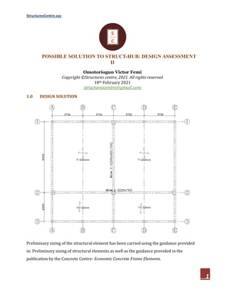
- 1. StructuresCentre.xyz 1 POSSIBLE SOLUTION TO STRUCT-HUB: DESIGN ASSESSMENT II Omotoriogun Victor Femi Copyright ©Structures centre, 2021. All rights reserved 18th February 2021 structurescentre@gmail.com 1.0 DESIGN SOLUTION Preliminary sizing of the structural element has been carried using the guidance provided in: Preliminary sizing of structural elements as well as the guidance provided in the publication by the Concrete Centre- Economic Concrete Frame Elements.
- 2. StructuresCentre.xyz 2 3.1 Actions 3.1 1 Roof Permanent Actions = 1.5𝑘𝑁/𝑚 Variable Actions = 0.6𝑘𝑁/𝑚 3.1.2 Floors Permanent Actions: i. Self weight of slab = 0.20 × 25 = 5𝑘𝑁/𝑚 (𝐶𝑙𝑎𝑠𝑠𝑟𝑜𝑜𝑚) = 0.15 × 25 = 3.75𝑘𝑁/𝑚 (𝑊𝑎𝑙𝑘𝑤𝑎𝑦) ii. Finishes & Services = 1.5𝑘𝑁/𝑚 iii. Partition Allowances = 1.0𝑘𝑁/𝑚 Total Permanent Actions = 𝑔 = 7.5𝑘𝑁/𝑚 & 6.25𝑘𝑁/𝑚 Variable Actions: i. Floor Imposed Loading (Classroom & Walkways) = 𝑞 = 3.0𝑘𝑁/𝑚 Design Value of Actions: By inspection the permanent actions are less than 4.5 times the variable actions, therefore equation 6.13b of BS EN 1990 will give the most unfavourable results. Roof Design Actions= 1.35𝜉𝑔 + 1.5𝑞 =(1.35 × 0.925 × 1.5) + (1.5 × 0.6) = 2.77𝑘𝑁𝑚 Design Permanent Load 1.35𝜉𝑔 = 1.35 × 0.925 × 1.5 = 1.87𝑘𝑁/𝑚 Classroom Panels Design Actions= 1.35𝜉𝑔 + 1.5𝑞 =(1.35 × 0.925 × 7.5) + (1.5 × 3) = 13.87𝑘𝑁𝑚 Design Permanent Load 1.35𝜉𝑔 = 1.35 × 0.925 × 7.5 = 9.37𝑘𝑁/𝑚 Walkway Panels Design Actions= 1.35𝜉𝑔 + 1.5𝑞 =(1.35 × 0.925 × 6.25) + (1.5 × 3) = 12.30𝑘𝑁𝑚
- 3. StructuresCentre.xyz 3 Design Permanent Load 1.35𝜉𝑔 = 1.35 × 0.925 × 6.25 = 7.80𝑘𝑁/𝑚 3.2 Slab Panels 3.2.1 Classroom Panels 𝐿 𝐿 = 9000 7500 = 1.2 (𝑇𝑤𝑜 𝑤𝑎𝑦 𝑆𝑙𝑎𝑏 − 𝑇𝑤𝑜 𝐴𝑑𝑗𝑎𝑐𝑒𝑛𝑡 𝑆𝑖𝑑𝑒𝑠 𝐷𝑖𝑠𝑐𝑜𝑛𝑡𝑖𝑛𝑜𝑢𝑠) Using coefficients from table for two ways slabs with two adjacent sides discontinuous. Short span coefficients = −0.064 & 0.047 Long span coefficients = −0.045 & 0.034 3.2.1.1 Flexural Design Negative Moment at Support (Short Span) 𝑀 = −0.064𝑛 , 𝑙 = −0.064 × 13.87 × 7.5 = −49.93𝑘𝑁. 𝑚/𝑚 Assuming cover to reinforcement of 20mm, 12mm bars d = h − c + links + ∅ = 200 − 20 + = 174mm; b = 1000mm k = M bd f = 49.93 × 10 1000 × 174 × 20 = 0.0825 z = d 0.5 + √0.25 − 0.882k ≤ 0.95d =d 0.5 + 0.25 − 0.882(0.0825) ≤ 0.95d =0.92d = 0.92 × 174 = 160.08mm A = M 0.87f z = 49.93 × 10 0.87 × 410 × 160.08 = 874.42mm /m Try Y12mm bars @ 125mm Centres (As, prov = 904mm2 ) Positive Moment at Midspan (Short Span) 𝑀 = 0.047𝑛 , 𝑙 = 0.047 × 13.87 × 7.5 = 36.67𝑘𝑁. 𝑚/𝑚 Assuming cover to reinforcement of 20mm, 12mm bars
- 4. StructuresCentre.xyz 4 d = h − c + links + ∅ = 200 − 20 + = 174mm; b = 1000mm k = M bd f = 36.67 × 10 1000 × 174 × 20 = 0.0606 z = d 0.5 + √0.25 − 0.882k ≤ 0.95d =d 0.5 + 0.25 − 0.882(0.0606) ≤ 0.95d =0.94d = 0.94 × 174 = 163.56mm A = M 0.87f z = 36.67 × 10 0.87 × 410 × 163.56 = 628.54mm /m Try Y12mm bars @ 125mm Centres (As, prov = 904mm2 ) Negative Moment at Support (Long Span) 𝑀 = −0.045𝑛 , 𝑙 = −0.045 × 13.87 × 7.5 = −35.11𝑘𝑁. 𝑚/𝑚 Assuming cover to reinforcement of 20mm, 12mm bars d = h − c + links + ∅ + ∅ = 200 − 20 + + 12 = 162mm; b = 1000mm k = M bd f = 35.11 × 10 1000 × 162 × 20 = 0.067 z = d 0.5 + √0.25 − 0.882k ≤ 0.95d =d 0.5 + 0.25 − 0.882(0.067) ≤ 0.95d =0.94d = 0.94 × 162 = 152.28mm A = M 0.87f z = 35.11 × 10 0.87 × 410 × 152.28 = 646.38mm /m Try Y12mm bars @ 150mm Centres (As, prov = 753mm2 ) Positive Moment at Midspan (Long Span) 𝑀 = 0.034𝑛 , 𝑙 = 0.034 × 13.87 × 7.5 = 26.53𝑘𝑁. 𝑚/𝑚 Assuming cover to reinforcement of 20mm, 12mm bars d = h − c + links + ∅ + ∅ = 200 − 20 + + 12 = 162mm; b = 1000mm
- 5. StructuresCentre.xyz 5 k = M bd f = 26.53 × 10 1000 × 162 × 20 = 0.051 z = d 0.5 + √0.25 − 0.882k ≤ 0.95d =d 0.5 + 0.25 − 0.882(0.051) ≤ 0.95d =0.95d = 0.95 × 162 = 153.9mm A = M 0.87f z = 26.53 × 10 0.87 × 410 × 153.9 = 483.28mm /m Try Y12mm bars @ 150mm Centres (As, prov = 753mm2 /m) 3.2.1.2 Deflection Verification Deflection verification can be carried using either of the two alternative method provided in section 7.4 of Eurocode 2 (Part 1). The conservative span-effective method and the rigorous calculation approach which involve using theoretical expression to estimate the actual deflection of the slab. The span-effective method is used here, the rigorous method is not suitable for hand calculations, spreadsheets or finite element software’s are required for fast calculations. Basic Requirement: ≥ = 𝑁 × 𝐾 × 𝐹1 × 𝐹2 × 𝐹3 𝜌 = 𝐴 , 𝐴 = 𝐴 , 𝑏𝑑 = 628.54 (1000 × 174) = 0.36% ρ = 10 f = 10 × √20 = 0.45% since ρ < ρ N = 11 + 1.5 f ρ ρ + 3.2 f ρ ρ − 1 = 11 + 1.5√20 × 0.45 0.36 + 3.2√20 0.45 0.36 − 1 = 21.20 F1 = 1.0 K = 1.3 (end spans)
- 6. StructuresCentre.xyz 6 F2 = 7.0 l = 7.0 7.5 = 0.93 F3 = 310 σ ≤ 1.5 σ = f γ g + φq n A , A , ∙ 1 δ = 410 1.15 × 7.5 + 0.6(3) 13.87 × 628.54 904 = 166.21Mpa F3 = 310 166.21 = 1.87 > 1.5 L d = 21.20 × 1.3 × 1.0 × 0.93 × 1.50 = 38.45 L d = span effective depth = 7500 174 = 43.10 Since actual span-effective depth ratio is greater than the limiting span-effective depth ratio. It shows that we might have a deflection problem. Hence, the options available includes, increasing the slab thickness, the concrete class or even the steel bars grade. However, readers are reminded that, the span/effective depth approach is only a fast and conservative method of verifying deflection. In this case the rigorous calculation method was used and the slab found to perform satisfactory with respect to deflection. 3.2.1.3 Detailing Checks. The minimum area of steel required in panel: A , = 0.26 f f 𝑏 d ≥ 0.0013bd f = 0.30f = 0.3 × 20 = 2.21Mpa A , = 0.26 × 2.21 410 × 1000 × 174 ≥ 0.0013 × 1000 × 174 = 243.85mm . By observation it is not critical anywhere in slab. Hence adopt all steel bars. 3.2.2 Walkway Panels The walkways panel are one-way slabs which can be idealized as propped cantilevers.
- 7. StructuresCentre.xyz 7 Moment in Spans 𝑀 = 𝑛 , 𝑙 10 = 12.30 × 2.25 10 = 6.23𝑘𝑁. 𝑚/𝑚 Since moment is relatively low. Provide Y12 @ 200mm Centres (As, prov = 565mm2 /m) 3.3 Concrete Beams 3.3.1 Beam C-C (300x750) 3.3.1.1 Actions on Beam Permanent Actions: Span 1 a. Equivalent uniformly distributed load transferred from slab to beam = 2 × 𝑛 𝑙 6 3 − 𝑙 𝑙 = 2 × 7.5 × 7.5 6 3 − 7.5 9.0 = 43.31kN/m b. self-weight of beam = (0.75 − 0.2) × 0.3 × 25 = 4.125kN/m c. Walls = (3.75 − 0.75) × 3.5 = 10.5kN/m Permanent Actions G = 43.31 + 4.125 + 10.5 = 57.94kN/m Span 2 a. Equivalent uniformly distributed load transferred from slab to beam = 0kN/m b. self-weight of beam = (0.45 − 0.15) × 0.3 × 25 = 2.25kN/m Permanent Actions G = 2.25kN/m Variable Actions: Span 1 a. Equivalent uniformly distributed load transferred from slab to beam = 2 × 𝑛 𝑙 6 3 − 𝑙 𝑙 = 2 × 3.0 × 7.5 6 3 − 7.5 9.0 = 17.32kN/m Variable Actions Q = 17.32kN/m Design Value of Actions on Beam
- 8. StructuresCentre.xyz 8 By inspection the permanent actions are less than 4.5 times the variable actions, therefore equation 6.13b of BS EN 1990 will give the most unfavourable results. Span 1: Design Load = 1.35𝜉𝐺 + 1.5𝑄 = (1.35 × 0.925 × 57.94) + (1.5 × 17.32) = 𝟗𝟖. 𝟑𝒌𝑵/𝒎 Design Permanent Load 1.35𝜉𝐺 = 1.35 × 0.925 × 57.94 = 𝟕𝟐. 𝟒𝒌𝑵/𝒎 Span 2: Design Load = 1.35𝜉𝐺 + 1.5𝑄 = (1.35 × 0.925 × 2.25) + (1.5 × 0) = 𝟑. 𝟖𝟎𝒌𝑵/𝒎 Design Permanent Load 1.35𝜉𝐺 = 1.35 × 0.925 × 2.25 = 𝟑. 𝟖𝟎𝒌𝑵/𝒎 3.3.1.2 Analysis of Beam Approximate methods of analysis could be used, this requires, the use of simple coefficients reflecting the approximate value of the internal forces within the structural element. However, an analysis of the subframe will be carried out here, with the basic aim of obtaining the loads & moment transferred to the column as well as the internal forces on the beam. Only the shear and bending moment diagrams are presented here. The reader is expected to already have a basic knowledge on analysis of subframes. However, guidance can be obtained from: How to Analyse Element in Frames. The load cases considered are: All spans loaded with the maximum design loads Alternate spans loaded with the maximum design load while the other spans are loaded with the design permanent actions
- 9. StructuresCentre.xyz 9 Figure 1: Subframe C-C Figure 2: Bending Moment Envelope Figure 3: Shear Force Envelope
- 10. StructuresCentre.xyz 10 3.3.1.3 Flexural Design End Support (3-2) M = 200.6kN. m Assuming cover to reinforcement of 25mm, 25mm tensile bars, 16mm compression bars & 8mm links d = c + links + ∅ 2 = 25 + 10 + 16 2 = 43𝑚𝑚 d = h − c + links + ∅ = 450 − 25 + 10 + = 402.5mm; b = 300mm k = M bd f = 200.6 × 10 300 × 402.5 × 20 = 0.021 > 0.168 (Section is doubly reinforced) 𝐴 = (𝑘 − 𝑘 )𝑓 𝑏𝑑 0.87𝑓 (𝑑 − 𝑑 ) = (0.21 − 0.168) × 20 × 300 × 404.5 0.87 × 410 × (402.5 − 43) = 321.54𝑚𝑚 Try 3Y16mm bars Bottom (As, prov = 602mm2 ). z = d 0.5 + √0.25 − 0.882k ≤ 0.95d =d 0.5 + 0.25 − 0.882(0.21) ≤ 0.95d =0.75d = 0.75 × 402.5 = 301.88mm A = 𝑘𝑓 𝑏𝑑 0.87f z + 𝐴 = 0.168 × 20 × 300 × 402.5 0.87 × 410 × 301.88 + 321.54 = 1838.08mm Try 4Y25mm bars Top (As, prov = 1962mm2 ). Interior Support (2-1) M = 531.4kN. m Assuming cover to reinforcement of 25mm, 25mm tensile bars, 16mm compression bars & 8mm links d = c + links + ∅ 2 = 25 + 10 + 16 2 = 43𝑚𝑚 d = h − c + links + ∅ = 750 − 25 + 10 + = 702.5mm; b = 300mm k = M bd f = 531.4 × 10 300 × 702.5 × 20 = 0.018 > 0.168 (Section is doubly reinforced)
- 11. StructuresCentre.xyz 11 𝐴 = (𝑘 − 𝑘 )𝑓 𝑏𝑑 0.87𝑓 (𝑑 − 𝑑 ) = (0.18 − 0.168) × 20 × 300 × 702.5 0.87 × 410 × (702.5 − 43) = 151.05𝑚𝑚 Try 3Y16mm bars Bottom (As, prov = 602mm2 ) . z = d 0.5 + √0.25 − 0.882k ≤ 0.95d =d 0.5 + 0.25 − 0.882(0.18) ≤ 0.95d =0.80d = 0.80 × 702.5 = 562mm A = 𝑘𝑓 𝑏𝑑 0.87f z + 𝐴 = 0.168 × 20 × 300 × 702.5 0.87 × 410 × 562 + 151.05 = 2632.55mm Try 4Y25mm + 4Y20mm bars Top (As, prov = 3218mm2 ). To be spread across the effective width. b = b + b , + b , ≤ b b , = 0.1l = 0.1 × 0.15(l + l ) = 0.1 × 0.15(2250 + 7500) = 146.25mm b = 300 + 146.25 + 146.25 = 592.5mm Therefore, this reinforcement will be spread across a width of 592.5mm. Span (2-1) M = 524.2kN. m Assuming cover to reinforcement of 25mm, two layers of 25mm tensile bars, 16mm compression bars & 8mm links d = c + links + ∅ 2 = 25 + 10 + 16 2 = 43𝑚𝑚 d = h − c + links + ∅ = 750 − 25 + 10 + = 677.5mm; b = b = b + b , + b , ≤ b b , = b , = 0.2b + 0.1𝑙 ≤ 0.2𝑙 𝑏 = 7500 − 150 − 150 2 = 3600𝑚𝑚 𝑙 = 0.85𝑙 = 0.85 × 9000 = 7650𝑚𝑚 b , = b , = (0.2 × 3600) + (0.1 × 7650) ≤ (0.2 × 7650) = 1485𝑚𝑚 b = 300 + 1485 + 1485 = 3270mm ≤ 3600mm k = M bd f = 524.2 × 10 3270 × 677.5 × 20 = 0.017
- 12. StructuresCentre.xyz 12 z = d 0.5 + √0.25 − 0.882k ≤ 0.95d =d 0.5 + 0.25 − 0.882(0.017) ≤ 0.95d =0.95d = 0.95 × 677.5 = 643.63mm We have to verify the position of the neutral axis: x = 2.5(d − z) = 2.5(677.5 − 643.63) = 84.68mm Therefore x < h = 84.68 < 200 (neutral axis is within the flange) Hence, we can design as a rectangular section. A = M 0.87f z = 524.2 × 10 0.87 × 410 × 643.63 = 2283.27mm Try 5Y25mm bars Bottom in two layers (As, prov = 2452.5mm2 ). End Support (1-2) M = 412.6kN. m Assuming cover to reinforcement of 25mm, 25mm tensile bars, 16mm compression bars & 8mm links d = c + links + ∅ 2 = 25 + 10 + 16 2 = 43𝑚𝑚 d = h − c + links + ∅ = 750 − 25 + 10 + = 702.5mm; b = 300mm k = M bd f = 412.6 × 10 300 × 702.5 × 20 = 0.14 < 0.168 (Section is singly reinforced) z = d 0.5 + √0.25 − 0.882k ≤ 0.95d =d 0.5 + 0.25 − 0.882(0.14) ≤ 0.95d =0.86d = 0.86 × 702.5 = 604.15mm A = M 0.87f z = 412.6 × 10 0.87 × 410 × 604.15 = 1914.6mm Try 3Y25mm +3Y20mm bars Top (As, prov = 2413mm2 ). To be spread across the effective width. 3.3.1.4 Shear Design By inspection, the critical section for shear occurs at the interior support 2, hence can be used to conservatively size the shear reinforcement for the whole beam.
- 13. StructuresCentre.xyz 13 𝑉 = (455.6 − 0.6775 × 98.3) = 389.0𝑘𝑁 𝑉 , = 0.18 𝛾 𝑘(100𝜌 𝑓 ) 𝑏 𝑑 ≥ 0.035𝑘 𝑓 𝑏 𝑑 𝑘 = 1 + 200 677.5 = 1 + 200 677.5 = 1.54 < 2 𝐴 = 2453𝑚𝑚 𝑏 = 300𝑚𝑚 𝜌 = 𝐴 𝑏 𝑑 = 2453 300 × 677.5 = 0.012 𝑉 , = 0.18 1.5 × 1.54 × (100 × 0.012 × 20) ∙ 300 × 677.5 ≥ 0.035 × 1.54 × √20 × 300 × 677.5 = 108.34kN Since 𝑉 > 𝑉 , (389.0𝑘𝑁 > 108.34𝑘𝑁) therefore shear reinforcement is required. 𝜃 = 0.5𝑠𝑖𝑛 5.56𝑉 𝑏 𝑑(1 − 𝑓 250 )𝑓 = 0.5𝑠𝑖𝑛 5.56 × 389.0 × 10 300 × 677.5 1 − 20 250 20 = 17.66° cot 𝜃 = cot 17.66 = 3.14 > 2.5 Hence take cot 𝜃 = 2.5 ≥ where z = 0.9d = 0.9 × 677.5 = 609.75mm A S ≥ 389.0 × 10 609.75 × 2.5 × 410 = 0.62 max spacing = 0.75d = 0.75 × 677.5 = 508.13mm 𝐴 , 𝑆 = 0.08 𝑓 𝑏 𝑓 = 0.08 × √20 × 300 410 = 0.26 Use Y10 @ 200mm centres (0.78). 3.3.1.5 Deflection Verification Deflection seems not to be critical in this beam, however for the purpose of illustration, the 9.0m span will be verified using the span-effective depth ratios.
- 14. StructuresCentre.xyz 14 = 𝑁 × 𝐾 × 𝐹1 × 𝐹2 × 𝐹3 𝜌 = 𝐴 , 𝐴 = 𝐴 , 𝑏 𝑑 + (𝑏 − 𝑏 )ℎ = 2283.27 (300 × 677.5) + (3270 − 300)200 = 0.29% ρ = 10 f = 10 × √20 = 0.45% since ρ < ρ N = 11 + 1.5 f ρ ρ + 3.2 f ρ ρ − 1 = 11 + 1.5√20 × 0.45 0.29 + 3.2√30 0.45 0.29 − 1 = 29.81 F1 = 0.82 K = 1.3 (end spans) F2 = 7.5 𝑙 = 7.5 9.0 = 0.83 F3 = 310 σ ≤ 1.5 σ = f γ g + φq n A , A , ∙ 1 δ = 410 1.15 × 57.94 + 0.6(17.32) 98.3 × 2283.27 2453 = 230.7Mpa F3 = 310 230.7 = 1.34 L d = 29.81 × 1.3 × 0.82 × 0.83 × 1.34 = 35.34 L d = span effective depth = 9000 677.5 = 13.28 Since the limiting span-effective depth ratio is greater than the actual span-effective depth ratio. It therefore follows that deflection has been satisfied in the end spans. 3.3.1.6 Detailing Checks Minimum Area of Steel A , = 0.26 f f 𝑏 d ≥ 0.0013bd f = 0.30f = 0.3 × 20 = 2.21Mpa
- 15. StructuresCentre.xyz 15 Hogging at Supports A , = 0.26 × 2.21 410 × 300 × 702.5 ≥ 0.0013 × 300 × 702.5 = 295.4mm . By observation it is not critical anywhere at the supports. Sagging in Spans A , = 0.26 × 2.21 410 × 300 × 677.5 ≥ 0.0013 × 300 × 677.5 = 284.99mm . By observation it is not critical anywhere in the spans. Hence adopt all attempted bars. 3.3.2 Beam 2-2 (225x750) 3.3.2.1 Actions on Beam Permanent Actions: Span 1 & 2 a. Equivalent uniformly distributed load transferred from slab to beam = 𝑛 , 𝑙 , 3 + 𝑛 , 𝑙 , 2 = (7.5 × 7.5) 3 + (6.25 × 2.25) 2 = 25.8kN/m b. self-weight of beam = (0.75 − 0.2) × 0.225 × 25 = 3.1kN/m c. Walls = (3.75 − 0.75) × 3.5 = 10.5kN/m Permanent Actions G = 25.8 + 3.1 + 10.5 = 39.4kN/m Variable Actions: Span 1 & 2 a. Equivalent uniformly distributed load transferred from slab to beam = 𝑛 , 𝑙 , 3 + 𝑛 , 𝑙 , 2 = (3.0 × 7.5) 3 + (3.0 × 2.25) 2 = 10.88kN/m Variable Actions Q = 10.88kN/m Design Value of Actions on Beam By inspection the permanent actions are less than 4.5 times the variable actions, therefore equation 6.13b of BS EN 1990 will give the most unfavourable results.
- 16. StructuresCentre.xyz 16 Span 1 & 2: Design Load = 1.35𝜉𝐺 + 1.5𝑄 = (1.35 × 0.925 × 39.4) + (1.5 × 10.88) = 𝟔𝟓. 𝟓𝟐𝒌𝑵/𝒎 Design Permanent Load 1.35𝜉𝐺 = 1.35 × 0.925 × 39.4 = 𝟒𝟗. 𝟐𝟎𝒌𝑵/𝒎 3.3.2.2 Analysis of Beam Coefficients for beam analysis can be used to determine the internal forces in this beam, since the spans are equal and uniformly loaded. However, in-order to determine the column moments, analysis of the entire subframe 2-2 will be carried out The load cases considered are: All spans loaded with the maximum design loads Alternate spans loaded with the maximum design load while the other spans are loaded with the design permanent actions Figure 4: Subframe 2-2
- 17. StructuresCentre.xyz 17 Figure 5: Bending Moment Envelope Figure 6: Shear Force Envelope 3.3.2.3 Flexural Design End Support (A & D) M = 172.5kN. m Assuming cover to reinforcement of 25mm, 20mm tensile bars, 16mm compression bars & 8mm links d = c + links + ∅ 2 = 25 + 10 + 16 2 = 43𝑚𝑚 d = h − c + links + ∅ = 750 − 25 + 10 + = 705mm; b = 225mm
- 18. StructuresCentre.xyz 18 k = M bd f = 172.5 × 10 225 × 705 × 20 = 0.078 < 0.168 (Section is singly reinforced) z = d 0.5 + √0.25 − 0.882k ≤ 0.95d =d 0.5 + 0.25 − 0.882(0.078) ≤ 0.95d =0.93d = 0.93 × 705 = 655.7mm A = M 0.87f z = 172.5 × 10 0.87 × 410 × 655.7 = 737.53mm Try 4Y16mm bars Top (As, prov = 1608mm2 ). Span (2-1) M = 206.0kN. m Assuming cover to reinforcement of 25mm, 20mm tensile bars, 16mm compression bars & 8mm links d = c + links + ∅ 2 = 25 + 10 + 16 2 = 43𝑚𝑚 d = h − c + links + ∅ = 750 − 25 + 10 + = 705mm; b = b = b + b , + b , ≤ b b , = 0.2𝑏 + 0.1𝑙 , ≤ 0.2𝑙 , 𝑏 = 9000 − 112.5 − 112.5 2 = 4387.5𝑚𝑚 𝑙 , = 0.85𝑙 = 0.85 × 7500 = 6375𝑚𝑚 b , = (0.2 × 4387.5) + (0.1 × 6375) ≤ (0.2 × 6375) = 1275𝑚𝑚 b , = 0.2𝑏 + 0.1𝑙 , ≤ 0.2𝑙 , 𝑏 = 2250 − 112.5 − 112.5 2 = 1012.5𝑚𝑚 𝑙 , = 0.85𝑙 = 0.85 × 7500 = 6375𝑚𝑚 b , = (0.2 × 1012.5) + (0.1 × 6375) ≤ (0.2 × 6375) = 840𝑚𝑚 b = 225 + 1275 + 840 = 2340mm ≤ 4387.5mm
- 19. StructuresCentre.xyz 19 k = M bd f = 206 × 10 2340 × 705 × 20 = 0.009 z = d 0.5 + √0.25 − 0.882k ≤ 0.95d =d 0.5 + 0.25 − 0.882(0.009) ≤ 0.95d =0.95d = 0.95 × 705 = 669.75mm We have to verify the position of the neutral axis: x = 2.5(d − z) = 2.5(705 − 669.75) = 88.13mm Therefore x < h = 88.13 < 200 (neutral axis is within the flange) Hence, we can design as a rectangular section. A = M 0.87f z = 206 × 10 0.87 × 410 × 669.75 = 862.3mm Try 3Y20mm bars Bottom in two layers (As, prov = 942mm2 ). Interior Support (C) M = 373.1kN. m Assuming cover to reinforcement of 25mm, two layers of 20mm tensile bars, 16mm compression bars & 8mm links d = c + links + ∅ 2 = 25 + 10 + 16 2 = 43𝑚𝑚 d = h − c + links + ∅ = 750 − 25 + 10 + = 705mm; b = 225mm k = M bd f = 373.1 × 10 225 × 685 × 20 = 0.167 < 0.168 (Section is singly reinforced) z = d 0.5 + √0.25 − 0.882k ≤ 0.95d =d 0.5 + 0.25 − 0.882(0.167) ≤ 0.95d =0.82d = 0.82 × 705 = 578.1mm A = M 0.87f z = 373.1 × 10 0.87 × 410 × 578.1 = 1809.3mm Try 6Y20mm bars Top (As, prov = 1884mm2 ) Spread across effective width of the beam.
- 20. StructuresCentre.xyz 20 3.3.2.4 Shear Design By inspection, the critical section for shear occurs at the interior support C, hence can be used to conservatively size the shear reinforcement for the whole beam. 𝑉 = (273.5 − 0.705 × 65.52) = 227.3𝑘𝑁 𝑉 , = 0.18 𝛾 𝑘(100𝜌 𝑓 ) 𝑏 𝑑 ≥ 0.035𝑘 𝑓 𝑏 𝑑 𝑘 = 1 + 200 705 = 1 + 200 705 = 1.53 < 2 𝐴 = 942𝑚𝑚 𝑏 = 225𝑚𝑚 𝜌 = 𝐴 𝑏 𝑑 = 942 225 × 705 = 0.0059 𝑉 , = 0.18 1.5 × 1.53 × (100 × 0.0059 × 20) ∙ 225 × 705 ≥ 0.035 × 1.53 × √20 × 225 × 705 = 66.3kN Since 𝑉 > 𝑉 , (389.0𝑘𝑁 > 66.3𝑘𝑁) therefore shear reinforcement is required. 𝜃 = 0.5𝑠𝑖𝑛 5.56𝑉 𝑏 𝑑(1 − 𝑓 250 )𝑓 = 0.5𝑠𝑖𝑛 5.56 × 227.3 × 10 225 × 705 1 − 20 250 20 = 12.8° cot 𝜃 = cot 12.8 = 4.40 > 2.5 Hence take cot 𝜃 = 2.5 ≥ where z = 0.9d = 0.9 × 705 = 634.5mm A S ≥ 227.3 × 10 634.5 × 2.5 × 410 = 0.34 max spacing = 0.75d = 0.75 × 705 = 528.75mm 𝐴 , 𝑆 = 0.08 𝑓 𝑏 𝑓 = 0.08 × √20 × 225 410 = 0.26 Use Y10 @ 200mm centres (0.78).
- 21. StructuresCentre.xyz 21 3.3.2.5 Deflection Verification = 𝑁 × 𝐾 × 𝐹1 × 𝐹2 × 𝐹3 𝜌 = 𝐴 , 𝐴 = 𝐴 , 𝑏 𝑑 + (𝑏 − 𝑏 )ℎ = 862.3 (225 × 705) + (2270 − 225)200 = 0.15% ρ = 10 f = 10 × √20 = 0.45% since ρ < ρ N = 11 + 1.5 f ρ ρ + 3.2 f ρ ρ − 1 = 11 + 1.5√20 × 0.45 0.15 + 3.2√20 0.45 0.15 − 1 = 63.1 F1 = 0.82 K = 1.3 (end spans) F2 = 1.0 F3 = 310 σ ≤ 1.5 σ = f γ g + φq n A , A , ∙ 1 δ = 410 1.15 × 39.4 + 0.6(10.88) 65.52 × 862.3 942 = 228.8Mpa F3 = 310 228.8 = 1.35 L d = 63.1 × 1.3 × 0.82 × 1.0 × 1.35 = 90.81 L d = span effective depth = 7500 705 = 10.64 Since the limiting span-effective depth ratio is greater than the actual span-effective depth ratio. It therefore follows that deflection has been satisfied. 3.3.2.6 Detailing Checks Minimum Area of Steel A , = 0.2687 f f 𝑏 d ≥ 0.0013bd f = 0.30f = 0.3 × 20 = 2.21Mpa
- 22. StructuresCentre.xyz 22 Hogging at Supports & Sagging in Spans A , = 0.26 × 2.21 410 × 225 × 705 ≥ 0.0013 × 300 × 702.5 = 222.3mm . By observation it is not critical anywhere at the supports. Hence adopt all attempted bars. 3.4 Concrete Columns 3.4.1 Column C2 3.4.1.1 Actions on Column Roof Permanent Action: a. Roof Load = 𝑔 , × 𝐴𝑟𝑒𝑎 = 1.5 × . ×( . . ) = 63.28𝑘𝑁 b. Beam self weight = 3.2 × . . . . = 42𝑘𝑁 c. Column Weight = (0.4 × 0.4 × 3.3) × 25 = 13.2𝑘𝑁 𝑮𝒌,𝒓𝒐𝒐𝒇 = 𝟔𝟑. 𝟔𝒌𝑵 Variable Actions: a. Roof Load = 𝑔 , × 𝐴𝑟𝑒𝑎 = 0.6 × . ×( . . ) = 25.3𝑘𝑁 𝑸𝒌,𝒓𝒐𝒐𝒇 = 𝟐𝟓. 𝟑𝒌𝑵 Floors Permanent Action: a. Roof Load = 𝑔 , × 𝐴𝑟𝑒𝑎 = 7.5 × . × + 6.25 × . × . = 305.86𝑘𝑁 b. Beam self weight = 3.2 × . . . . = 42𝑘𝑁 c. Walls = 10.5 × . . . . = 137.81𝑘𝑁 d. Column Weight = (0.4 × 0.4 × 3.0) × 25 = 12𝑘𝑁 𝑮𝒌,𝒇𝒍𝒐𝒐𝒓𝒔 = 𝟒𝟗𝟕. 𝟕𝒌𝑵 Variable Actions: a. Roof Load = 𝑔 , × 𝐴𝑟𝑒𝑎 = 3.0 × . ×( . . ) = 126.6𝑘𝑁
- 23. StructuresCentre.xyz 23 𝑸𝒌,𝒓𝒐𝒐𝒇 = 𝟏𝟐𝟔. 𝟔𝒌𝑵 Imposed Reduction Factors α = 1 − = 1 − ( . × ) = 0.83 ≥ 0.75 ; 𝛼 = 0.83 (same for all floors) α = 1 − 0 10 = 1 − 0 10 = 1.0 for 3rd − Roof α = 1 − 1 10 = 1 − 1 10 = 0.9 for 2nd − 3rd floor α = 1 − 2 10 = 1 − 2 10 = 0.8 for 1st − 2nd floor α = 1 − 3 10 = 1 − 3 10 = 0.7 for Ground − 1st floor Table 1: Load Take Down for Column C2 Floors 𝛼 𝛼 𝐺 (kN) 𝐺 (kN) . 𝑄 (kN) 𝑄 (kN) . 𝑄 (kN) . 3rd -Roof 0.83 1.0 63.6 63.6 25.3 25.3 21.0 2nd – 3rd Floor 0.83 0.9 497.7 561.3 126.6 151.9 126.1 1st – 2nd Floor 0.83 0.8 497.7 1059 126.6 278.5 222.8 G – 1st Floor 0.83 0.7 497.7 1556.7 126.6 405.1 283.57 The bending moment on the column is obtained from the analysis of the subframes 2-2 and C-C. The roof subframe have not been analysed, the roof moments are also determined through a similar process applied at the floors. Table 2: Bending Moments on Column C2 Floor 𝑀 , 𝑀 , 𝑀 , 𝑀 , 3rd -Roof -21.5 165.4 -5.7 18.3 2nd -3rd Floor -165.4 165.4 -18.3 18.3 1st -2nd Floor -165.4 165.4 -18.3 18.3 G-1st Floor -165.4 82.7 -18.3 9.2
- 24. StructuresCentre.xyz 24 3.4.1.1 Column Design The column has been sized to be “stocky” hence slenderness need not to be verified. 3rd Floor - Roof Design Axial Action By inspection the permanent actions are less than 4.5 times the variable actions, therefore equation 6.13b of BS EN 1990 will give the most unfavourable results. 𝑁 = 1.35𝜉𝐺 + 1.5𝑄 = 1.35(0.925 × 63.6) + (1.5 × 21) = 𝟏𝟏𝟎. 𝟗𝒌𝑵 Design Moments Y-Y Direction 𝑀 , = 𝑚𝑎𝑥|𝑀 ; 𝑀 | 𝑀 , = 𝑚𝑎𝑥 𝑀 ; 𝑀 + 𝑒 𝑁 = 165.4 + 0.75 × 3750 400 × 110.9 ∙ 10 = 166.2𝑘𝑁. 𝑚 𝑀 , = 𝑁 𝑒 ; 𝑒 = = ≥ 20 = 20𝑚𝑚 𝑀 , = (110.9 × 20) ∙ 10 = 2.2𝑘𝑁. 𝑚 M , = max|166.2 ; 2.2| = 𝟏𝟔𝟔. 𝟐𝐤𝐍. 𝐦 Z-Z Direction 𝑀 , = 𝑚𝑎𝑥|𝑀 ; 𝑀 | 𝑀 , = 𝑚𝑎𝑥 𝑀 ; 𝑀 + 𝑒 𝑁 = 18.3 + 0.75 × 3750 400 × 110.9 ∙ 10 = 19.1𝑘𝑁. 𝑚 𝑀 , = 𝑁 𝑒 ; 𝑒 = = ≥ 20 = 20𝑚𝑚 𝑀 , = (110.9 × 20) ∙ 10 = 2.2𝑘𝑁. 𝑚 M , = max|19.1 ; 2.2| = 𝟏𝟗. 𝟏𝐤𝐍. 𝐦 Having obtained our design moments, the column is designed in the most critical direction (y-y axis) and we then conclude by checking out biaxial bending.
- 25. StructuresCentre.xyz 25 Design Using Chart 𝑑 = ℎ − 𝑐 + ∅ 2 + 𝑙𝑖𝑛𝑘𝑠 = 400 − 25 + 20 2 + 8 = 357𝑚𝑚 𝑑 ℎ = 357 400 = 0.89 ; 𝑈𝑠𝑒 𝑐ℎ𝑎𝑟𝑡 𝑓𝑜𝑟 0.85 𝑁 𝑏ℎ𝑓 = 110.9 × 10 (400 × 400) × 20 = 0.03; 𝑀 𝑏ℎ𝑓 = 166.2 × 10 (400 × 400 ) × 20 = 0.13 𝐴 𝑓 𝑏ℎ𝑓 = 0.35 𝐴 = 0.35 𝑏ℎ𝑓 𝑓 0.35 × (400 × 400) × 20 410 = 𝟐𝟕𝟐𝟑. 𝟕𝒎𝒎𝟐 Try 10Y20mm Bars (As.prov = 3140mm2 ) 𝐴 , = 0.1 𝑁 0.87𝑓 ≥ 0.002𝐴 = 0.1 × 110.9 × 10 0.87 × 410 ≥ 0.002(400 × 400) = 320𝑚𝑚 𝐴 , = 0.04𝐴 = 0.04 × (400 × 400) = 6400𝑚𝑚 𝐴 , < 𝐴 < 𝐴 , = (320𝑚𝑚 < 2723.7𝑚𝑚 < 6400𝑚𝑚 ) O.K Use 10Y20 bars 𝑨𝒔,𝒑𝒓𝒐 (𝟑𝟏𝟒𝟎𝒎𝒎𝟐 ) – Containment Links Link diameter = 𝑚𝑎𝑥 6 ; ∅ = 𝑚𝑎𝑥 6 ; ; 𝑈𝑠𝑒 8𝑚𝑚 Link spacing = 𝑚𝑖𝑛{20∅ ; 𝑏 ; 400𝑚𝑚} = min 0.6 × {20 × 20 ; 400 ; 400𝑚𝑚} = 240mm Use 2T8 links at 200mm centre. By inspection, biaxial bending is not critical for this column stack, hence the check can be ignored. 2nd - 3rd Floor Design Axial Action By inspection the permanent actions are less than 4.5 times the variable actions, therefore equation 6.13b of BS EN 1990 will give the most unfavourable results.
- 26. StructuresCentre.xyz 26 𝑁 = 1.35𝜉𝐺 + 1.5𝑄 = 1.35(0.925 × 561.3) + (1.5 × 126.1) = 𝟖𝟗𝟏𝒌𝑵 Design Moments Y-Y Direction 𝑀 , = 𝑚𝑎𝑥|𝑀 ; 𝑀 | 𝑀 , = 𝑚𝑎𝑥 𝑀 ; 𝑀 + 𝑒 𝑁 = 165.4 + 0.75 × 3750 400 × 891 ∙ 10 = 171.7𝑘𝑁. 𝑚 𝑀 , = 𝑁 𝑒 ; 𝑒 = = ≥ 20 = 20𝑚𝑚 𝑀 , = (891 × 20) ∙ 10 = 17.82𝑘𝑁. 𝑚 M , = max|171.7 ; 17.82| = 𝟏𝟕𝟏. 𝟕𝐤𝐍. 𝐦 Z-Z Direction 𝑀 , = 𝑚𝑎𝑥|𝑀 ; 𝑀 | 𝑀 , = 𝑚𝑎𝑥 𝑀 ; 𝑀 + 𝑒 𝑁 = 18.3 + 0.75 × 3750 400 × 891 ∙ 10 = 24.6𝑘𝑁. 𝑚 𝑀 , = 𝑁 𝑒 ; 𝑒 = = ≥ 20 = 20𝑚𝑚 𝑀 , = (891 × 20) ∙ 10 = 17.82𝑘𝑁. 𝑚 M , = max|24.6 ; 17.82| = 𝟏𝟗. 𝟏𝐤𝐍. 𝐦 The column is designed in the most critical direction (y-y axis) and we then conclude by checking out biaxial bending. Design Using Chart 𝑑 = ℎ − 𝑐 + ∅ 2 + 𝑙𝑖𝑛𝑘𝑠 = 400 − 25 + 25 2 + 8 = 354.5𝑚𝑚 𝑑 ℎ = 354.5 400 = 0.89 ; 𝑈𝑠𝑒 𝑐ℎ𝑎𝑟𝑡 𝑓𝑜𝑟 0.85 𝑁 𝑏ℎ𝑓 = 891 × 10 (400 × 400) × 20 = 0.3; 𝑀 𝑏ℎ𝑓 = 171.7 × 10 (400 × 400 ) × 20 = 0.13 𝐴 𝑓 𝑏ℎ𝑓 = 0.20 𝐴 = 0.20 𝑏ℎ𝑓 𝑓
- 27. StructuresCentre.xyz 27 0.20 × (400 × 400) × 20 410 = 𝟏𝟓𝟔𝟏𝒎𝒎𝟐 Try 10Y20mm Bars (As.prov = 3140mm2 ) 𝐴 , = 0.1 𝑁 0.87𝑓 ≥ 0.002𝐴 = 0.1 × 891 × 10 0.87 × 410 ≥ 0.002(400 × 400) = 320𝑚𝑚 𝐴 , = 0.04𝐴 = 0.04 × (400 × 400) = 6400𝑚𝑚 𝐴 , < 𝐴 < 𝐴 , = (320𝑚𝑚 < 1561𝑚𝑚 < 6400𝑚𝑚 ) O.K Use 10Y20 bars 𝑨𝒔,𝒑𝒓𝒐 = (𝟑𝟏𝟒𝟎𝒎𝒎𝟐 ) – Containment Links Link diameter = 𝑚𝑎𝑥 6 ; ∅ = 𝑚𝑎𝑥 6 ; ; 𝑈𝑠𝑒 8𝑚𝑚 Link spacing = 𝑚𝑖𝑛{20∅ ; 𝑏 ; 400𝑚𝑚} = min 0.6 × {20 × 20 ; 400 ; 400𝑚𝑚} = 240mm Use 2T8 links at 200mm centre. By inspection, biaxial bending is not critical for this column stack, hence the check can be ignored. 1st - 2nd Floor Design Axial Action By inspection the permanent actions are greater than 4.5 times the variable actions, therefore equation 6.13a of BS EN 1990 will give the most unfavourable results. 𝑁 = 1.35𝐺 + 1.5𝜓𝑄 = 1.35(1059) + (1.5 × 0.7 × 126.1) = 𝟏𝟓𝟔𝟐. 𝟏𝒌𝑵 Design Moments Y-Y Direction 𝑀 , = 𝑚𝑎𝑥|𝑀 ; 𝑀 | 𝑀 , = 𝑚𝑎𝑥 𝑀 ; 𝑀 + 𝑒 𝑁 = 165.4 + 0.75 × 3750 400 × 1562.1 ∙ 10 = 176.4𝑘𝑁. 𝑚 𝑀 , = 𝑁 𝑒 ; 𝑒 = = ≥ 20 = 20𝑚𝑚 𝑀 , = (1562.1 × 20) ∙ 10 = 31.2𝑘𝑁. 𝑚
- 28. StructuresCentre.xyz 28 M , = max|176.4 ; 31.2| = 𝟏𝟕𝟔. 𝟒𝐤𝐍. 𝐦 Z-Z Direction 𝑀 , = 𝑚𝑎𝑥|𝑀 ; 𝑀 | 𝑀 , = 𝑚𝑎𝑥 𝑀 ; 𝑀 + 𝑒 𝑁 = 18.3 + 0.75 × 3750 400 × 1562.1 ∙ 10 = 29.3𝑘𝑁. 𝑚 𝑀 , = 𝑁 𝑒 ; 𝑒 = = ≥ 20 = 20𝑚𝑚 𝑀 , = (1562.1 × 20) ∙ 10 = 31.2𝑘𝑁. 𝑚 M , = max|29.3 ; 31.2| = 𝟑𝟏. 𝟐𝐤𝐍. 𝐦 The column is designed in the most critical direction (y-y axis) and we then conclude by checking out biaxial bending. Design Using Chart 𝑑 = ℎ − 𝑐 + ∅ 2 + 𝑙𝑖𝑛𝑘𝑠 = 400 − 25 + 25 2 + 8 = 354.5𝑚𝑚 𝑑 ℎ = 354.5 400 = 0.89 ; 𝑈𝑠𝑒 𝑐ℎ𝑎𝑟𝑡 𝑓𝑜𝑟 0.85 𝑁 𝑏ℎ𝑓 = 1562.1 × 10 (400 × 400) × 20 = 0.49; 𝑀 𝑏ℎ𝑓 = 176.4 × 10 (400 × 400 ) × 20 = 0.14 𝐴 𝑓 𝑏ℎ𝑓 = 0.40 𝐴 = 0.40 𝑏ℎ𝑓 𝑓 0.40 × (400 × 400) × 20 410 = 𝟑𝟏𝟐𝟐𝒎𝒎𝟐 Try 12Y20mm Bars (As.prov = 3768mm2 ) 𝐴 , = 0.1 𝑁 0.87𝑓 ≥ 0.002𝐴 = 0.1 × 1562.1 × 10 0.87 × 410 ≥ 0.002(400 × 400) = 438𝑚𝑚 𝐴 , = 0.04𝐴 = 0.04 × (400 × 400) = 6400𝑚𝑚 𝐴 , < 𝐴 < 𝐴 , = (438𝑚𝑚 < 3122𝑚𝑚 < 6400𝑚𝑚 ) O.K Use 12Y20 bars 𝑨𝒔,𝒑𝒓𝒐 = (𝟑𝟕𝟖𝟖𝒎𝒎𝟐 )
- 29. StructuresCentre.xyz 29 – Containment Links Link diameter = 𝑚𝑎𝑥 6 ; ∅ = 𝑚𝑎𝑥 6 ; ; 𝑈𝑠𝑒 8𝑚𝑚 Link spacing = 𝑚𝑖𝑛{20∅ ; 𝑏 ; 400𝑚𝑚} = min 0.6 × {20 × 20 ; 400 ; 400𝑚𝑚} = 240mm Use 2T8 links at 200mm centre. By inspection, biaxial bending is not critical for this column stack, hence the check can be ignored. Ground – 1st Floor Design Axial Action By inspection the permanent actions are greater than 4.5 times the variable actions, therefore equation 6.13a of BS EN 1990 will give the most unfavourable results. 𝑁 = 1.35𝐺 + 1.5𝜓𝑄 = 1.35(1556.7) + (1.5 × 0.7 × 283.57) = 𝟐𝟑𝟗𝟗. 𝟑𝒌𝑵 Design Moments Y-Y Direction 𝑀 , = 𝑚𝑎𝑥|𝑀 ; 𝑀 | 𝑀 , = 𝑚𝑎𝑥 𝑀 ; 𝑀 + 𝑒 𝑁 = 165.4 + 0.75 × 3750 400 × 2399.3 ∙ 10 = 182.3𝑘𝑁. 𝑚 𝑀 , = 𝑁 𝑒 ; 𝑒 = = ≥ 20 = 20𝑚𝑚 𝑀 , = (2399.3 × 20) ∙ 10 = 47.99𝑘𝑁. 𝑚 M , = max|182.3 ; 47.99| = 𝟏𝟖𝟐. 𝟑𝐤𝐍. 𝐦 Z-Z Direction 𝑀 , = 𝑚𝑎𝑥|𝑀 ; 𝑀 | 𝑀 , = 𝑚𝑎𝑥 𝑀 ; 𝑀 + 𝑒 𝑁 = 18.3 + 0.75 × 3750 400 × 2399.3 ∙ 10 = 35.17𝑘𝑁. 𝑚 𝑀 , = 𝑁 𝑒 ; 𝑒 = = ≥ 20 = 20𝑚𝑚 𝑀 , = (2399.3 × 20) ∙ 10 = 47.99𝑘𝑁. 𝑚
- 30. StructuresCentre.xyz 30 M , = max|35.17 ; 47.99| = 𝟒𝟕. 𝟗𝟗𝐤𝐍. 𝐦 The column is designed in the most critical direction (y-y axis) and we then conclude by checking out biaxial bending. Design Using Chart 𝑑 = ℎ − 𝑐 + ∅ 2 + 𝑙𝑖𝑛𝑘𝑠 = 400 − 25 + 25 2 + 8 = 354.5𝑚𝑚 𝑑 ℎ = 354.5 400 = 0.89 ; 𝑈𝑠𝑒 𝑐ℎ𝑎𝑟𝑡 𝑓𝑜𝑟 0.85 𝑁 𝑏ℎ𝑓 = 2399.3 × 10 (400 × 400) × 20 = 0.75; 𝑀 𝑏ℎ𝑓 = 182.3 × 10 (400 × 400 ) × 20 = 0.142 𝐴 𝑓 𝑏ℎ𝑓 = 0.65 𝐴 = 0.65 𝑏ℎ𝑓 𝑓 0.65 × (400 × 400) × 20 410 = 𝟓𝟎𝟕𝟑. 𝟐𝒎𝒎𝟐 Try 12Y25mm Bars (As.prov = 5886mm2 ) 𝐴 , = 0.1 𝑁 0.87𝑓 ≥ 0.002𝐴 = 0.1 × 2339.3 × 10 0.87 × 410 ≥ 0.002(400 × 400) = 438𝑚𝑚 𝐴 , = 0.04𝐴 = 0.04 × (400 × 400) = 6400𝑚𝑚 𝐴 , < 𝐴 < 𝐴 , = (655.8𝑚𝑚 < 5073.2𝑚𝑚 < 6400𝑚𝑚 ) O.K Use 12Y25 bars 𝑨𝒔,𝒑𝒓𝒐 = (𝟓𝟖𝟖𝟔𝒎𝒎𝟐 ) – Containment Links Link diameter = 𝑚𝑎𝑥 6 ; ∅ = 𝑚𝑎𝑥 6 ; ; 𝑈𝑠𝑒 8𝑚𝑚 Link spacing = 𝑚𝑖𝑛{20∅ ; 𝑏 ; 400𝑚𝑚} = min 0.6 × {20 × 25 ; 400 ; 400𝑚𝑚} = 240mm Use 2T8 links at 200mm centre. By inspection, biaxial bending is not critical for this column stack, hence the check can be ignored.
- 31. StructuresCentre.xyz 31 3.5 Pad Foundation to Column C2 3.5.1 Serviceability Limit State 𝐺 = 1556.7𝑘𝑁 𝑄 = 283.57𝑘𝑁 𝑁 = 1.0𝐺 + 1.0𝑄 = 1556.7 + 283.57 = 1840.3𝑘N Assume 10% increase in axial actions to actions to account for footing self weight 𝑇𝑜𝑡𝑎𝑙 𝑙𝑜𝑎𝑑 = (1 + 0.1) × 1840.3 = 2024.3𝑘𝑁 𝐴𝑟𝑒𝑎 𝑟𝑒𝑞𝑢𝑖𝑟𝑒𝑑 = 𝑇𝑜𝑡𝑎𝑙 𝑙𝑜𝑎𝑑 𝑏𝑒𝑎𝑟𝑖𝑛𝑔 𝑟𝑒𝑠𝑖𝑠𝑡𝑎𝑛𝑐𝑒 = 2024.3 150 = 13.5𝑚 Assume a square base: length = breadth √13.5 = 3.67𝑚 Provide a Base of 3.7m × 3.7m (say 0.6m deep) 𝐴𝑟𝑒𝑎 𝑝𝑟𝑜𝑣𝑖𝑑𝑒𝑑 = 13.69𝑚 3.5.1 Ultimate Limit State N = 1.35G + 1.5Q = (1.35 × 1556.7) + (1.5 × 283.57) = 2527kN bearing pressure = Design axial action Area provided = N A = 2527 (3.7 × 3.7) = 184.6kN/m Punching check at Column face Assume cover to reinforcement is 50mm and reinforcement of 16mm d = h − c + ϕ 2 = 600 − 50 + 16 2 = 542mm Verify that N ≤ V , 𝑉 , = 0.2 1 − 𝑓 250 𝑓 𝑝 𝑑 = 0.2 1 − 20 250 20 × (4 × 400) × 542 × 10 = 3191.3𝑘𝑁 Thus (𝑁 = 2527𝑘𝑁) < 𝑉 , = (3191.3kN) O. K Flexural Design 𝑙𝑒𝑣𝑒𝑟 𝑎𝑟𝑚 @ 𝑓𝑎𝑐𝑒 𝑜𝑓 𝑐𝑜𝑙𝑢𝑚𝑛 = (3.7 − 0.40) 2 = 1.65𝑚 𝑀 = 𝑝𝑙 2 = 184.6 × 1.65 2 = 162.0𝑘𝑁. 𝑚/m 𝑘 = 𝑀 𝑏𝑑 𝑓 = 162 × 10 10 × 542 × 20 = 0.028 < 0.168 𝑧 = 𝑑 0.5 + √0.25 − 0.882𝑘 ≤ 0.95𝑑
- 32. StructuresCentre.xyz 32 = 0.95𝑑 = 0.95 × 542 = 514.9𝑚𝑚 𝐴 = 𝑀 0.87𝑓 𝑧 = 162 × 10 0.87 × 410 × 514.9 = 882.04𝑚𝑚 /m 𝑇𝑟𝑦 𝑌16 − 150 𝑐𝑒𝑛𝑡𝑟𝑒𝑠 𝑏𝑜𝑡ℎ 𝑤𝑎𝑦𝑠 𝐴 , = 1340𝑚𝑚 /𝑚 Punching Shear at Basic Control Perimeter 2.0d from column face 𝑉 = 𝑁 − ∆𝑉 ∆𝑉 = 𝑝A 𝐴 = 𝑐 𝑐 + 𝜋(2𝑑) + 4(𝑐 + 𝑐 )𝑑 = 400 + 𝜋(2 × 542) + 4(400 + 400)542 = 5.6𝑚 𝑝 = 2(𝑐 + 𝑐 ) + 4𝜋𝑑 = 2(400 + 400) + 4𝜋(542) = 8414𝑚𝑚 𝑉 = 2527 − 184.6(5.6) = 1493𝑘𝑁 𝑣 = 𝑉 𝑝 𝑑 = 1493 × 10 8414 × 542 = 0.33𝑀𝑝𝑎 𝑣 , = 0.12𝑘(100𝜌𝑓 ) / ≥ 0.035𝑘 / 𝑓 𝜌 = = × = 0.0025 ; 𝑘 = 1 + = 1 + = 1.61 < 2 𝑣 , = 0.12 × 1.61(100 × 0.0025 × 20) / ≥ 0.035 × 1.61 √20 = 0.33𝑀𝑝𝑎 𝑆𝑖𝑛𝑐𝑒 (𝑣 = 0.33𝑀𝑝𝑎) ≤ (𝑣 , = 0.33𝑀𝑝𝑎) 𝐶𝑟𝑖𝑡𝑖𝑐𝑎𝑙 𝑏𝑢𝑡 𝑂. 𝑘. Transverse shear: Taken at 1.0d from the face of the column 𝑉 = 𝑝(1.325 − 1.0d) = 184.6 × (1.65 − 0.542) = 204.6𝑘𝑁/𝑚 𝑣 = 𝑉 𝑏𝑑 = 204.6 × 10 1000 × 542 = 0.38 𝑣 , = 0.33𝑀𝑝𝑎 (as before) (𝑣 = 0.36𝑀𝑝𝑎) = (𝑣 , = 0.36𝑀𝑝𝑎) 𝑁𝑜𝑡 𝑂. 𝐾. Since the base is barely passing in punching and failing in transverse shear, the base thickness can be increased to 650mm. Verify Minimum Area of Steel 𝐴 , = 0.078𝑓 / 𝑓 𝑏 d ≥ 0.0013𝑏 𝑑
- 33. StructuresCentre.xyz 33 𝐴 , = 0.078(20) / 410 × 1000 × 542 ≥ 0.0013 × 1000 × 542 = 876.5𝑚𝑚 < 1340𝑚𝑚 o. k Use 24T16-150 both ways 3.6 Design Summary Figure 7: Slab Reinforcement Summary
- 34. StructuresCentre.xyz 34 Figure 8: Summary of Reinforcement in Beam C-C Figure 9: Summary of Reinforcement in Beam 2-2
- 35. StructuresCentre.xyz 35 Figure 10: Summary of Reinforcement in Column C2 Figure 11: Summary of Pad Base to Column C2