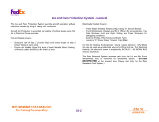
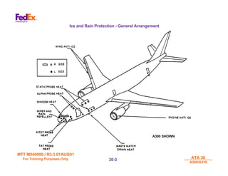
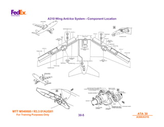
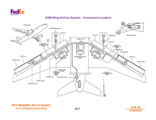
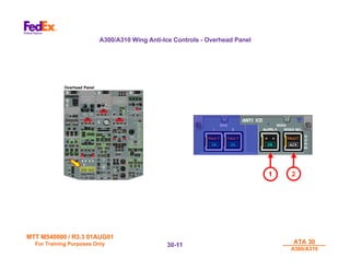
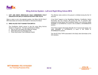
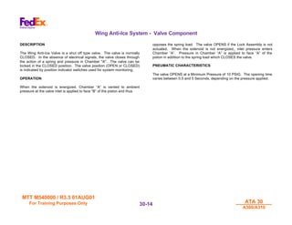
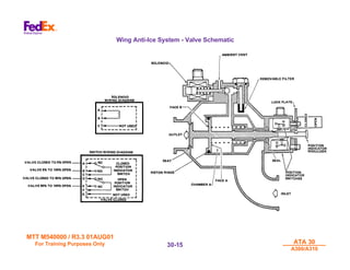
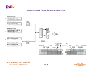
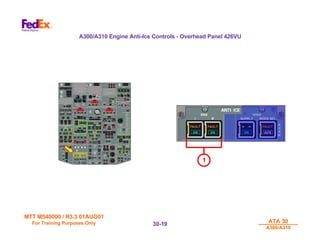
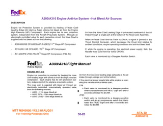
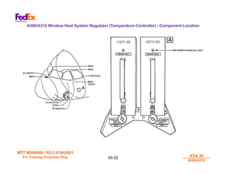
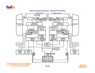
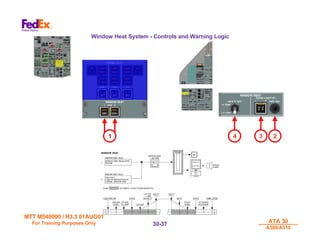
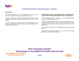
SlideShare a Scribd company logo
MTT M540000 / R3.3 01AUG01
For Training Purposes Only
For Training Purposes Only ATA 30
ATA 30
A300/A310
A300/A310
30-
30-1
1
ATA 30
ATA 30
Ice and Rain
Ice and Rain
Protection
Protection
MTT M540000 / R3.3 01AUG01
For Training Purposes Only
For Training Purposes Only ATA 30
ATA 30
A300/A310
A300/A310
30-
30-2
2
Ice and Rain Protection System - General
The Ice and Rain Protection System permits aircraft operation without
restriction caused by icing or heavy rain conditions.
Aircraft Ice Protection is provided by heating of critical areas using Hot
Air or Electrical Power sources.
Hot Air Heated Area(s):
- Outboard half of Slat 2 (Center Slat) and entire length of Slat 3
(Outer Slats) of each wing
- Engine Air Intakes (Nose Lip area of each Nacelle Nose Cowling,
commonly called the D-Duct Air Inlet Lip area
Electrically Heated Area(s):
- Fresh Water (Potable Water) and Lavatory “A” Service Panels
- Front Windshields (Captain and First Officer) for ice protection, Two
Side Windows (Left and Right Sliding and Fixed Windows) for
defogging conditions
- External Probes, Pitot Tubes and Static Ports
- Lavatory “A” Waste Water Forward Drain Mast
For Hot Air Heating, the Engine(s) 1 and 2 supply bleed air. APU Bleed
Air may be used as an alternate source for Wing Anti-Ice. For Electrical
Heating, the electrical power is supplied by AC BUS 1, AC NORM BUS
and DC ESS BUS.
The Rain Removal System removes rain from the LH and RH Front
Windshields that is achieved by windshield wipers. SYSTEM
DEACTIVATED at the present time (Heavy rain only, by the Rain
Repellent Fluid System.)
MTT M540000 / R3.3 01AUG01
For Training Purposes Only
For Training Purposes Only ATA 30
ATA 30
A300/A310
A300/A310
30-
30-3
3
Ice and Rain Protection - General Arrangement
A300 SHOWN
MTT M540000 / R3.3 01AUG01
For Training Purposes Only
For Training Purposes Only ATA 30
ATA 30
A300/A310
A300/A310
30-
30-4
4
A300/A310 Wing Anti-Ice System
DESCRIPTION
Ice Protection System for the wings is ensured by heating the leading
edge of the Center Slats (Slat Number 2)(Outboard Half) and the leading
edge of the Outer Slats (Slat Number 3)(Full Length). Hot Bleed air,
supplied by the Engines (Engines 1 and 2) or the APU (Up to 15,000
feet), is ducted in each wing from the fixed leading edge supply duct into
the outer slat through a telescopic tube.
The Hot Bleed Air is then distributed along this slat by a piccolo tube and
also into the Center Slat piccolo tube by a flexible connection across the
slats gap. Finally the Hot Bleed Air, after heating the concerned slats,
exhausts overboard through vent holes distributed along the slat rear
skin.
Each wing is equipped with two Anti-Ice Shutoff Valves (Solenoid
Controlled and Pneumatically Operated) (NORMAL and ALTERNATE)
are arranged in parallel position.
• With Engine Bleed Air Supply, only one valve is active, as selected
• With APU Bleed Air Supply, both valves are active regardless of
mode selection
A Flow Limiting Restrictor is fitted down stream of each valve.
When WING ANTI ICE SUPPLY is switched ON, a signal is passed to
the Pneumatic System which increases the hot air temperature at the
Precooler outlet 227 Degrees Celsius (441°F) instead of 177 Degrees
Celsius (351°F), and if operating on APU. Bleed Air, the APU Bleed Air
flow will be increased.
If, during operation, an Anti-Ice Valve fails to OPEN the other valve can
be selected for operation. Without Electrical or Pneumatic Supply the
valves are springloaded to the CLOSED position.
The Wing Anti-Ice Valves will CLOSE automatically if:
• Either Engine FIRE Handle is pulled while the AIR BLEED X-FEED
valve is CLOSED
• The Main Landing Gear Shock Absorbers (Struts) are compressed
(Weight on Wheels)
On the ground, by the Landing Gear Shock Absorber Torque Links
(Weight on Wheels), if the Wing Anti-Ice System is selected ON,
overheating of the Slat Number 2 and 3 structure is prevented by means
of a Time Delay Relay which limits the Anti-Ice Valve opening time to 10
seconds during the Test Operation of the system..
MTT M540000 / R3.3 01AUG01
For Training Purposes Only
For Training Purposes Only ATA 30
ATA 30
A300/A310
A300/A310
30-
30-5
5
A310 Wing Anti-Ice System - Component Location
MTT M540000 / R3.3 01AUG01
For Training Purposes Only
For Training Purposes Only ATA 30
ATA 30
A300/A310
A300/A310
30-
30-6
6
A300/A310 Wing Anti-Ice System
DESCRIPTION
Ice Protection System for the wings is ensured by heating the leading
edge of the Center Slats (Slat Number 2)(Outboard Half) and the leading
edge of the Outer Slats (Slat Number 3)(Full Length). Hot Bleed air,
supplied by the Engines (Engines 1 and 2) or the APU (Up to 15,000
feet), is ducted in each wing from the fixed leading edge supply duct into
the outer slat through a telescopic tube.
The Hot Bleed Air is then distributed along this slat by a piccolo tube and
also into the Center Slat piccolo tube by a flexible connection across the
slats gap. Finally the Hot Bleed Air, after heating the concerned slats,
exhausts overboard through vent holes distributed along the slat rear
skin.
Each wing is equipped with two Anti-Ice Shutoff Valves (Solenoid
Controlled and Pneumatically Operated) (NORMAL and ALTERNATE)
are arranged in parallel position.
• With Engine Bleed Air Supply, only one valve is active, as selected
• With APU Bleed Air Supply, both valves are active regardless of
mode selection
A Flow Limiting Restrictor is fitted down stream of each valve.
When WING ANTI ICE SUPPLY is switched ON, a signal is passed to
the Pneumatic System which increases the hot air temperature at the
Precooler outlet 227 Degrees Celsius (441°F) instead of 177 Degrees
Celsius (351°F), and if operating on APU. Bleed Air, the APU Bleed Air
flow will be increased.
If, during operation, an Anti-Ice Valve fails to OPEN the other valve can
be selected for operation. Without Electrical or Pneumatic Supply the
valves are springloaded to the CLOSED position.
The Wing Anti-Ice Valves will CLOSE automatically if:
• Either Engine FIRE Handle is pulled while the AIR BLEED X-FEED
valve is CLOSED
• The Main Landing Gear Shock Absorbers (Struts) are compressed
(Weight on Wheels)
On the ground, by the Landing Gear Relay on the Shock Absorber
Torque Links (Weight on Wheels), if the Wing Anti-Ice System is
selected ON, overheating of the Slat Number 2 and 3 structure is
prevented by means of a Time Delay Relay which limits the Anti-Ice
Valve opening time to 10 seconds during the Test Operation of the
system..
MTT M540000 / R3.3 01AUG01
For Training Purposes Only
For Training Purposes Only ATA 30
ATA 30
A300/A310
A300/A310
30-
30-7
7
A300 Wing Anti Ice System - Component Location
MTT M540000 / R3.3 01AUG01
For Training Purposes Only
For Training Purposes Only ATA 30
ATA 30
A300/A310
A300/A310
30-
30-8
8
Wing Anti-Ice System - RH ECAM Display
GENERAL DESCRIPTION
The Blue Color Anti-Ice indication is illuminated only when the Wing Anti-
Ice is selected ON.
NOTE: The RH ECAM Air Bleed Page, which is associated with the Anti-
Ice System, will only be called up during low bleed air pressure
conditions.
MTT M540000 / R3.3 01AUG01
For Training Purposes Only
For Training Purposes Only ATA 30
ATA 30
A300/A310
A300/A310
30-
30-9
9
Wing Anti-Ice System - Schematic
MTT M540000 / R3.3 01AUG01
For Training Purposes Only
For Training Purposes Only ATA 30
ATA 30
A300/A310
A300/A310
30-
30-10
10
Wing Anti-Ice System - Wing Bleed Air Supply
1. WING/SUPPLY PUSHBUTTON SWITCH
The PushButton Switch has a control function. The lower part
incorporates a Blue ON legend.
If ON legend is illuminated to ON:
• In flight, the Wing Anti-Ice System is selected ON for the wings.
• On the ground, control is inhibited by the Landing Gear Relays
(Weight on Wheels).
If ON legend is extinguished to OFF:
• Valves are held in the CLOSED position
2. WING/MODE SEL PUSHBUTTON SWITCH
The pushbutton switch provides two functions:
• Selection
• Monitoring
ALTN: The selection function is associated with the White ALTN
legend incorporated in the lower part of the Wing/Mode Selection
PushButton Switch. The ALTN legend illuminates when the
pushbutton switch is released (out)
ALTN-Legend ON: The Alternate Valves are selected
ALTN-Legend OFF: The Normal Valves are selected
This function is. inhibited with APU Bleed Air Supply selected in
flight. In this case the four valves are selected.
• FAULT: The monitoring function is associated with the Amber
Fault legend incorporated in the upper part of the Wing/Mode
Selection pushbutton switch.
The Amber FAULT legend illuminates to indicate:
• One of the valves does not CLOSE in the following
configurations:
• ON legend illuminated OFF
• ON legend illuminated ON, on ground, test not selected
• ON legend illuminated ON in flight, when the valve is not
selected ,
• One of the valves does not OPEN in the following
configurations:
• ON legend illuminated ON in flight, when the valve is
selected
• ON legend illuminated ON, on the ground, with test selected,
during the first 10 seconds, with APU Bleed Air Supply
• When the FAULT legend illuminates ON, the central warnings
are activated. The FAULT legend illuminates ON briefly when
the valves are selected OPEN, thus indicating that monitoring is
performed through a Five (5)-Second Time Delay, without
activating the central warnings.
• When the FAULT legend illuminates ON with Engine Bleed Air
Supply, the Alternate Valves are selected. If the legend remains
ON, the system is cut off.
• When the FAULT legend illuminates ON with APU Bleed Air
Supply and Engine Bleed Air Supply, the Alternate Valves area
selected. If the legend remains ON, the system is cut off.
• When the FAULT legend illuminates ON with APU Bleed Air
Supply, Engine Bleed Air Supply can be selected. If this is not
possible, the system must be cut off.
MTT M540000 / R3.3 01AUG01
For Training Purposes Only
For Training Purposes Only ATA 30
ATA 30
A300/A310
A300/A310
30-
30-11
11
A300/A310 Wing Anti-Ice Controls - Overhead Panel
Overhead Panel
2
1
MTT M540000 / R3.3 01AUG01
For Training Purposes Only
For Training Purposes Only ATA 30
ATA 30
A300/A310
A300/A310
30-
30-12
12
Wing Anti-Ice System - Left and Right Wing Valves MFA
1. LEFT AND RIGHT WING/VALVE FAULT MEMORIZED FAULT
ANNUNCIATOR (MFA) IS ASSOCIATED WITH ONE VALVE
When a valve is not in the selected position, the White VALVE FAULT
MFA illuminates and remains illuminated to memorize the failure.
2. WING VALVES TEST PUSHBUTTON SWITCH
The PushButton Switch serves to test the using Wing Anti-Ice
System on the ground. The test is performed as follows:
a. Start up APU and select APU Bleed Air Supply
b. Select Wing Anti-Ice (ON legend ON)
c. Press Wing Valves Test PushButton Switch
The effective valve control on the ground is inhibited during the first 10
seconds.
If the FAULT legend on the Wing/Mode Selection PushButton Switch
illuminates ON and remains ON during the first 10 seconds after
pressing the Wing Valves Test PushButton Switch, one of the four valves
(NORMAL or ALTERNATE) is stuck in the CLOSED or INTERMEDIATE
position.
If the FAULT legend illuminates ON after the 10 second test period, one
valve (NORMAL or ALTERNATE) is stuck in the OPEN or
INTERMEDIATE position.
The VALVE FAULT MFA associated to the faulty valve illuminates to the
ON indication.
MTT M540000 / R3.3 01AUG01
For Training Purposes Only
For Training Purposes Only ATA 30
ATA 30
A300/A310
A300/A310
30-
30-13
13
Wing Anti-Ice System - Anti Ice Test Panel - BITE Controls
Maintenance Panel
2
1
1
MTT M540000 / R3.3 01AUG01
For Training Purposes Only
For Training Purposes Only ATA 30
ATA 30
A300/A310
A300/A310
30-
30-14
14
Wing Anti-Ice System - Valve Component
DESCRIPTION
The Wing Anti-Ice Valve is a shut off type valve. The valve is normally
CLOSED. In the absence of electrical signals, the valve closes through
the action of a spring and pressure in Chamber "A". The valve can be
locked in the CLOSED position. The valve position (OPEN or CLOSED)
is indicated by position indicator switches used for system monitoring.
OPERATION
When the solenoid is energized, Chamber “A” is vented to ambient
pressure at the valve inlet is applied to face “B” of the piston and thus
opposes the spring load. The valve OPENS if the Lock Assembly is not
actuated. When the solenoid is not energized,, inlet pressure enters
Chamber “A”. Pressure in Chamber “A” is applied to face “A” of the
piston in addition to the spring load which CLOSES the valve.
PNEUMATIC CHARACTERISTICS
The valve OPENS at a Minimum Pressure of 10 PSIG. The opening time
varies between 0.5 and 5 Seconds, depending on the pressure applied.
MTT M540000 / R3.3 01AUG01
For Training Purposes Only
For Training Purposes Only ATA 30
ATA 30
A300/A310
A300/A310
30-
30-15
15
Wing Anti-Ice System - Valve Schematic
MTT M540000 / R3.3 01AUG01
For Training Purposes Only
For Training Purposes Only ATA 30
ATA 30
A300/A310
A300/A310
30-
30-16
16
A300/A310 Wing Anti-Ice System - Warning Logic
Below is depicted the various warnings displayed in the Flight Compartment in the event the shown fault
occurs within the Wing Anti-Ice System. Also shown graphically are the various Flight Phases at which the
warnings will or will not be displayed.
MTT M540000 / R3.3 01AUG01
For Training Purposes Only
For Training Purposes Only ATA 30
ATA 30
A300/A310
A300/A310
30-
30-17
17
Wing and Engine Anti-Ice System - Warning Logic
MTT M540000 / R3.3 01AUG01
For Training Purposes Only
For Training Purposes Only ATA 30
ATA 30
A300/A310
A300/A310
30-
30-18
18
Engine Air Intake Anti-Ice - Panel 426VU Controls
1. ENG 1 OR ENG 2 P/B SWITCH
Controls Engine Anti-Ice System for the related Engine 1 or 2.
• ON (P/B Switch pressed in): ON light illuminates Blue. Anti-Ice
Valves OPEN. The indication ENG ANTI-ICE is indicated and
shown on the LH ECAM MEMO Page.
• OFF (P/B Switch released out): ON light extinguishes. Both
valves close.
• FAULT: The light illuminates Amber Color if a valve position
does not agree with the PB Switch selection. FAULT light
illuminates momentarily during valve transit. If FAULT Light
remains illuminated for more than 3 seconds, the ECAM System
is activated.
MTT M540000 / R3.3 01AUG01
For Training Purposes Only
For Training Purposes Only ATA 30
ATA 30
A300/A310
A300/A310
30-
30-19
19
A300/A310 Engine Anti-Ice Controls - Overhead Panel 426VU
1
MTT M540000 / R3.3 01AUG01
For Training Purposes Only
For Training Purposes Only ATA 30
ATA 30
A300/A310
A300/A310
30-
30-20
20
A300/A310 Engine Anti-Ice System - Hot Bleed Air Sources
DESCRIPTION
Engine Ice Protection System is .provided by heating of Nose Cowl
Leading Edge (Air Inlet Lip Area) utilizing hot bleed air from the Engine
High Pressure (HP) Compressor. Each engine has its own protection
system, independent from the Aircraft Pneumatic System. Through an
electrically controlled valve for each respective circuit, the Nose Cowl is
supplied with hot bleed air from the following:
- A300-600/GE CF6-80C2A5F (FADEC)/11TH
Stage HP Compressor
- A310-200 / GE CF6-80A3 / 10
TH
Stage HP Compressor
- A31-200/PW JT9D-7R4/15
TH
Stage HP Compressor (PS4 Air)
Air from the Nose Cowl Leading Edge is exhausted overboard of the Air
Intake through a single port at the bottom of the Nose Cowl Assembly.
When an Nose Cowl Anti-Ice Valve is OPEN, a signal is passed to the
Thrust Control Computer, which decreases the thrust limit relative to
ambient conditions, engine operating conditions and anti-ice bleed load.
If, while the engine is operating, the electrical power supply, fails, the
Nacelle Nose Cowl Anti-Ice Valve OPENS.
Each valve is monitored by a Disagree Position Switch.
MTT M540000 / R3.3 01AUG01
For Training Purposes Only
For Training Purposes Only ATA 30
ATA 30
A300/A310
A300/A310
30-
30-21
21
Engine Air Intake Anti-Ice - Schematic
MTT M540000 / R3.3 01AUG01
For Training Purposes Only
For Training Purposes Only ATA 30
ATA 30
A300/A310
A300/A310
30-
30-22
22
Nacelle Nose Cowl Air Intake - CF6 Engine Anti-Ice Valve
This is a normally-open valve with solenoid controlled shutoff. Valve inlet
air pressure is routed through a filter to the reference pressure regulator,
passes around the metering valve of the regulator and is sensed on the
underside of the regulator diaphragm.
When this sensed pressure reaches the desired level, the spring force is
overcome and the metering valve moves toward the seat to maintain the
reference regulator output pressure at a constant level.
Manual override is provided by applying torque to the hexagon shaft and
rotating in the desired direction to open or close. When the desired
position has been reached, the spring-loaded detent automatically locks
the shaft.
Visual position indication is provided as well as electrical position
indication at the valve open and close positions.
MTT M540000 / R3.3 01AUG01
For Training Purposes Only
For Training Purposes Only ATA 30
ATA 30
A300/A310
A300/A310
30-
30-23
23
Nacelle Nose Cowl Air Intake - GE CF 6 Engine Anti-Ice Valve Component
MTT M540000 / R3.3 01AUG01
For Training Purposes Only
For Training Purposes Only ATA 30
ATA 30
A300/A310
A300/A310
30-
30-24
24
Probe Heat System - Ice Protection Components
To prevent the formation of ice on the Air Data System Probes, electrical
Probe Heating System is provided for:
• Pitot tubes
• Static Ports
• Alpha (angle of attack) Probes
• TAT (Total Air Temperature) Probes
The system is arranged in three independent channels (CAPT, F/O,
STBY). Pitot Tubes have two heating levels. Change over occurs
automatically from LOW Heating level on the Ground to HIGH heating
level In Flight.
MTT M540000 / R3.3 01AUG01
For Training Purposes Only
For Training Purposes Only ATA 30
ATA 30
A300/A310
A300/A310
30-
30-25
25
Probe Heating System - Component Location
MTT M540000 / R3.3 01AUG01
For Training Purposes Only
For Training Purposes Only ATA 30
ATA 30
A300/A310
A300/A310
30-
30-26
26
Probe Heating System - Ice Protection Components - Continued
Two parts of the alpha probes (angle of attack) are heated (case and
vane).
Only failure of vane heating will be indicated to crew.
To avoid erroneous indications, the TAT probes are not heated on the
ground.
The TAT probe light will not illuminate on the ground even with the
system ON.
If probe heat is not selected ON, or if any failure or discrepancy of probe
heating occurs, the respective PROBE HEAT lights on the overhead
panel will illuminate.
MTT M540000 / R3.3 01AUG01
For Training Purposes Only
For Training Purposes Only ATA 30
ATA 30
A300/A310
A300/A310
30-
30-27
27
Probe Heating System Ice Protection - Monitoring Logic
MTT M540000 / R3.3 01AUG01
For Training Purposes Only
For Training Purposes Only ATA 30
ATA 30
A300/A310
A300/A310
30-
30-28
28
Probe Heating System - Warning Logic
Below is depicted the various warnings displayed in the Flight Compartment in the event the shown fault
occurs within the Probe Heating System. Also shown graphically are the various Flight Phases at which the
warnings will or will not be displayed.
MTT M540000 / R3.3 01AUG01
For Training Purposes Only
For Training Purposes Only ATA 30
ATA 30
A300/A310
A300/A310
30-
30-29
29
Probe Heat System - Warning Logic
MTT M540000 / R3.3 01AUG01
For Training Purposes Only
For Training Purposes Only ATA 30
ATA 30
A300/A310
A300/A310
30-
30-30
30
Probe Heating System - Flight Compartment Controls and Indications
1. TAT, ENG 1 OR. 2, L OR R STAT, PITOT, ALPHA LIGHTS
Lights illuminate Amber, if:
- Respective probe heat circuit not selected ON
- Probe Heating Supply failed
- Probe Heating Control failed
If a PITOT light illuminates on the Ground, in addition to the above
causes the system may be in the high heating mode due to failure of
switchover.
If a PITOT light illuminates In Flight, in addition to the above causes
the system may be in the LOW heating mode due to failure of
switchover.
Illumination of a PROBE HEAT light is accompanied by ECAM
Activation.
NOTE: The TAT light remains extinguished (OFF) when switched ON
on the ground although the probe is not heated.
2. CAPT, F/O, STBY P/B SWITCHES
Controls the activation of Probe Heating System of their respective
circuits.
• ON (PB Switch pressed in)
Probe heating is activated. Respective PROBE HEAT lights will
extinguish.
• OFF (PB Switch released out)
OFF light illuminates White. Probe heating is deactivated.
Respective PROBE HEAT lights illuminate Amber.
MTT M540000 / R3.3 01AUG01
For Training Purposes Only
For Training Purposes Only ATA 30
ATA 30
A300/A310
A300/A310
30-
30-31
31
PROBE HEATING SYSTEM - Overhead Panel 433VU
1
2
MTT M540000 / R3.3 01AUG01
For Training Purposes Only
For Training Purposes Only ATA 30
ATA 30
A300/A310
A300/A310
30-
30-32
32
Flight Compartment Window Heat System - General Description
DESCRIPTION
The Flight Compartment Windows are electrically heated; the Front
Windshields for ice protection and defogging, the Side Windows (Sliding
and Fixed) for defogging only.
Two Anti-Ice Regulators (Windshield Heat Temperature Controllers)
control the Front Windshield temperatures to 35°C/42°C. A Temperature
Sensor in each windshield signals the actual temperature to the related
regulator, which accordingly activates or deactivates the heating power
supply from regulator control to the heating elements of Windshield and
Side Windows.
The two Side Windows heat is not temperature controlled.
A Regulator Unit failure results in illuminating the FAULT light on the
WINDOW HEAT Panel 433VU.
Front Windshields are heated on two heating power levels. LOW heating
power is used on the Ground. HIGH heating power is used In Flight.
Window Heat failure warnings are provided by two FAULT indications
and the ECAM Activation.
On the Maintenance Panel 472VU, the WINDOW HEAT Test Panel
provides Controls and Indications for testing the Heating Power Supply
and for testing the Protection and Warning circuits are installed.
MTT M540000 / R3.3 01AUG01
For Training Purposes Only
For Training Purposes Only ATA 30
ATA 30
A300/A310
A300/A310
30-
30-33
33
A300/A310 Window Heat System Regulator (Temperature Controller) - Component Location
MTT M540000 / R3.3 01AUG01
For Training Purposes Only
For Training Purposes Only ATA 30
ATA 30
A300/A310
A300/A310
30-
30-34
34
Windshield Windows Anti-Icing and Defogging System - Component Operation
DESCRIPTION
The Flight Compartment windows are electrically heated; the windshield
panels for ice protection and defogging, the two Side Windows (Sliding
and Fixed) for defogging only.
Two window temperature controllers control the windshield temperatures
to 35°C/42°C. A temperature sensor in each windshield panel signals the
actual. temperature to the related controller, which accordingly activates
or deactivates the heating power supply from the control module of the
controller to the heating elements of the windshield and side windows.
The windshield may be heated on two heating power levels. LOW
heating power is used on the ground. HIGH heating power is for In Flight
use only. It is inhibited on the Ground.
Illumination of two FAULT legends and activation of the ECAM System
indicate Window Heat System failure.
Devices for testing the Heating Power Supply and the Protection and
Warning circuits are provided on the WINDOW HEAT section of the
Maintenance Panel 472VU. A Window Heat Protection Unit is installed
between the Window Temperature Controller and the windows
(Windshield Windows, Sliding and Fixed Side Window ).
Each side is provided with one Protection Unit. The unit serves to protect
the Window Heat Controller against over voltage due to lightning strikes
or to the discharge of electrostatic loads accumulated on the windows to
the airframe structure. These induced over voltages pass through the
Sensor and/or Power Supply wires and the protection consists in
reducing the over voltages on each wire.
MTT M540000 / R3.3 01AUG01
For Training Purposes Only
For Training Purposes Only ATA 30
ATA 30
A300/A310
A300/A310
30-
30-35
35
Window Heating System - General Schematic
MTT M540000 / R3.3 01AUG01
For Training Purposes Only
For Training Purposes Only ATA 30
ATA 30
A300/A310
A300/A310
30-
30-36
36
Window Heating System - Overhead Panel 433VU and Maintenance Panel 472VU Controls
1. PWR L OR it P/B SWITCH
Controls activation of Window Heat System left or right hand sides.
• ON (PB Switch pressed in): Power is supplied to the Anti-Ice
Regulator. Heating elements in the window panes are supplied,
Front and Side windows are heated.
• OFF (PB Switch released out): OFF/R light illuminates White.
Window heat system is deactivated.
• FAULT: The light illuminates Amber if the related Window Heat
System has failed. Heating power is disconnected and
disconnection latched in the event of:
• Front Windshield temperature of less than -60°C or greater
than +60°C
• Failure of Sensing or Regulation Circuit
• Loss of 28VDC Power Supply to the Regulator
The FAULT light will extinguish after:
• Recovery of 28VDC Power Supply to Anti-Ice Regulator
• Selection of PWR PB Switch to OFF/R
Illumination of the FAULT light is accompanied by ECAM Activation.
2. PWR TEST PUSHBUTTON
Activates test of heating power supply to Front LH/RH Windshields
and Side Windows, at the same time for both sides. Before test, the
PWR PB Switches on the Overhead Panel 433VU must be selected
to ON.
When the pushbutton is pressed, the TEST OK lights will illuminate if
the Heating Power Supply is satisfactory. The duration of test is
limited by a Time Relay to 10 seconds.
3. OK LIGHTS
Lights illuminate White during PWR TEST to indicate satisfactory
condition of Window Heat Power Supply.
4. SAFETY TEST SELECTOR
Controls test of Temperature Control and Warning Circuits. Before
test the PWR PB Switches on the Overhead Panel 433VU must be
selected ON. The SAFETY TEST selector is springloaded to neutral
(Center Position).
• TEMP HI: Front Windshield temperature in excess of 60°C is
simulated
• Both FAULT lights illuminate on Overhead Panel 433VU
• Heating Power Supply is disconnected
• ECAM Activation
• NEUTRAL: Test circuit is de-energized. To cancel the warnings
and to reset the, system, the PWR PB Switches must be,
selected OFF/R (OFF/RESET) after the test.
• TEMP LO: Front Windshield temperature less than -60°C is
simulated. Indications will be identical to test in TEMP HI
position.
MTT M540000 / R3.3 01AUG01
For Training Purposes Only
For Training Purposes Only ATA 30
ATA 30
A300/A310
A300/A310
30-
30-37
37
Window Heat System - Controls and Warning Logic
4 3 2
1
MTT M540000 / R3.3 01AUG01
For Training Purposes Only
For Training Purposes Only ATA 30
ATA 30
A300/A310
A300/A310
30-
30-38
38
Front Windshield Rain Protection System - Operation
DESCRIPTION
Rain Removal System for the Front Windshields is provided by two
wipers. Each wiper is driven by a two-speed electric motor.
They are controlled by two WIPER Rotary Selectors Switches on the
Overhead Panel 429VU; one for the Captain and one for the F/O (First
Officer).
The Wiper System has a parking position of the wiper blade with the
scraper, just lifted from the window face, to avoid accumulation of sand
and scratching of the glass.
SYSTEM DEACTIVATED: FOR INFORMATIONAL PURPOSES ONLY
IN THE EVENT THE SYSTEM IS REACTIVATED AT A LATER DATE.
The Rain Repellent System is provided as an aid to improve visibility
through Front Windshields in heavy rain.
It includes a pressurized bottle, which supplies rain repellent fluid through
two time-controlled solenoid valves to the spray nozzles and two
pushbuttons for operation; one for each side for the Captain and First
Officer (F/O).
Timing devices limit the amount of rain repellent fluid for one application
cycle.
The system is automatically purged by hot air from the Hot Air Supply
Manifold of the Air Conditioning System.
Rain Protection System
Deactivated on All A300/A310 FedEx Fleet Aircraft
MTT M540000 / R3.3 01AUG01
For Training Purposes Only
For Training Purposes Only ATA 30
ATA 30
A300/A310
A300/A310
30-
30-39
39
Windshield Wiper and Rain Repellent System - Schematic
Rain Protection System
Deactivated on All A300/A310 FedEx Fleet Aircraft
FOR INFORMATIONAL PURPOSES ONLY
MTT M540000 / R3.3 01AUG01
For Training Purposes Only
For Training Purposes Only ATA 30
ATA 30
A300/A310
A300/A310
30-
30-40
40
Windshield Rain Repellent Fluid Can Replacement - General Procedure
WARNING: IF SKIN OR EYES ARE ACCIDENTALLY EXPOSED TO
RAIN REPELLENT FLUID, FLUSH AREA IMMEDIATELY WITH
WATER.
CAUTION: DO NOT ALLOW ANY SPILLED REPELLENT FLUID TO
REMAIN IN CONTACT WITH AIRCRAFT STRUCTURE. TO PREVENT
CORROSION, ALL REPELLENT FLUID SHOULD BE WASHED OFF
WITH SOAP AND WATER WITHIN 2 HOURS.
RAIN REPELLENT FLUID CAN REMOVAL
A. Connect hose to bleed valve on fluid gauge and place free end in a
container.
B. Press bleed button to depressurize the system.
WARNING: THE RAIN REPELLENT SYSTEM MUST NOT BE LEFT
WITHOUT A FLUID CAN INSTALLED UNLESS THE SYSTEM BLEED
PORT IS OPENED. UNDESIRABLY HIGH PRESSURE CAN DEVELOP
IN THE SYSTEM UNDER CERTAIN AMBIENT TEMPERATURE
CONDITIONS.
C. Open clamp securing can to partition. Unscrew and remove can. Also
remove and discard seal.
INSTALLATION
A. Install seal, then manually screw can onto fluid gauge.
B. Close and secure can retaining clamp.
C. Press bleed button, then check that level of fluid in gauge rises.
D. Check system for leaks.
Rain Protection System
Deactivated on All A300/A310 FedEx Fleet Aircraft
FOR INFORMATIONAL PURPOSES ONLY
MTT M540000 / R3.3 01AUG01
For Training Purposes Only
For Training Purposes Only ATA 30
ATA 30
A300/A310
A300/A310
30-
30-41
41
Windshield Rain Repellent System - Component Location
Rain Protection System
Deactivated on All A300/A310 FedEx Fleet Aircraft
FOR INFORMATIONAL PURPOSES ONLY
MTT M540000 / R3.3 01AUG01
For Training Purposes Only
For Training Purposes Only ATA 30
ATA 30
A300/A310
A300/A310
30-
30-42
42
Front Windshield Wiper System - Component Description
DESCRIPTION
Two wipers are available; one for the Left Windshield Pane (Captain) and
one for the Right Windshield Pane (First Officer).
The two wipers are independently actuated through two-speed electric
motors controlled by the WIPER Rotary Control Switches located on the
Flight Compartment Overhead Panel 429VU.
The wipers have a parking position clear of the area of visibility. The
wiper blades are slightly lifted from the windshield face to avoid sand
accumulation which could cause scratching of the windshield.
Each wiper system consists of the following components:
• Windshield Wiper Motor
• Flexible Drive Shaft
• Mechanical Converter Unit
• Wiper Arm with Wiper Blade
• Associated Flight Compartment Controls
MTT M540000 / R3.3 01AUG01
For Training Purposes Only
For Training Purposes Only ATA 30
ATA 30
A300/A310
A300/A310
30-
30-43
43
Front Windshield Wiper System - Component Location
MTT M540000 / R3.3 01AUG01
For Training Purposes Only
For Training Purposes Only ATA 30
ATA 30
A300/A310
A300/A310
30-
30-44
44
Front Windshield Wiper System - Controls and Operation Cycles
1. CAPTAIN AND FIRST OFFICER (F/O) WIPER ROTARY
SELECTOR SWITCHES
The Rotary Selector Switches control the Windshield Wiper Motors
on each side of the Left and Right Front Windshields.
FAST: Wipers operate at 150 Cycles/Minute.
SLOW: Wipers operate at 75 Cycles/Minute.
OFF: Wiper operation stops in PARKING position. Wipers are
out of view for the Flight Deck Crew or Maintenance Crew.
MTT M540000 / R3.3 01AUG01
For Training Purposes Only
For Training Purposes Only ATA 30
ATA 30
A300/A310
A300/A310
30-
30-45
45
Front Windshield Wiper System - Control Panel 429VU
1
MTT M540000 / R3.3 01AUG01
For Training Purposes Only
For Training Purposes Only ATA 30
ATA 30
A300/A310
A300/A310
30-
30-46
46
Drain Mast Ice Protection
DESCRIPTION AND OPERATION
Waste water from the Lavatory “A” Wash Basin (Sink) is dumped
overboard through the Forward Drain Mast located on the forward belly
area of the fuselage. To prevent ice formation in or around the drain
mast, electrical heating is provided both on the Ground and in the Air (In
Flight).
The Drain Mast have decals located on each side of the mast to identify
the mast is heated and could be HOT (Depending on the System
Configuration while in the GROUND MODE) The Drain Mast Circuit
Breaker can be pulled to deactivate the mast heating circuit during
Ground Parking and/or Maintenance Conditions. The words HOT on
each side of the Drain Mast are in Red Color
The plumbing system carries waste water from Lavatory “A”
Compartment Wash Basin (Sink) to Lower Forward Drain Mast located
on 'the outer skin of the aircraft.
Lavatory “A” Drain Mast is an electrically heated tube, shrouded by an
aerodynamically shaped, cast aluminum fairing.
The Heating Element is rated at 285 Watts. On the Ground it is supplied
with 28 VAC from an Autotransformer.
In Flight 115 VAC is routed to a Rectifier which supplies the heating
element with 100 VDC / + 3 VDC.
On the Ground the Heating Element can be operated using 115 VAC for
a maximum of Five (5) minutes.
MTT M540000 / R3.3 01AUG01
For Training Purposes Only
For Training Purposes Only ATA 30
ATA 30
A300/A310
A300/A310
30-
30-47
47
Lavatory “A” Drain Mast Ice Protection System - Component Location
MTT M540000 / R3.3 01AUG01
For Training Purposes Only
For Training Purposes Only ATA 30
ATA 30
A300/A310
A300/A310
30-
30-48
48
THIS PAGE INTENTIONALLY
LEFT BLANK
ATA 30 - END
COURSE CODE - M540000

More Related Content

Similar to ATA 30.pdf

B737 NG Air Systems
B737 NG Air SystemsB737 NG Air Systems
B737 NG Air Systems
theoryce
 
Plant Air & Inst Air.ppt
Plant Air & Inst Air.pptPlant Air & Inst Air.ppt
Plant Air & Inst Air.ppt
MeherabHossainJihad
 
ATA 28.pdf
ATA 28.pdfATA 28.pdf
ATA 28.pdf
Tate40
 
ATA 21 AIR CONDITIONING FOR AIRBUS 320.pdf
ATA 21 AIR CONDITIONING FOR AIRBUS 320.pdfATA 21 AIR CONDITIONING FOR AIRBUS 320.pdf
ATA 21 AIR CONDITIONING FOR AIRBUS 320.pdf
RaulMel
 
SunMaxx Datasheet Submittal - XMaxx Solar Hot Water Balancing Valves
SunMaxx Datasheet Submittal - XMaxx Solar Hot Water Balancing ValvesSunMaxx Datasheet Submittal - XMaxx Solar Hot Water Balancing Valves
SunMaxx Datasheet Submittal - XMaxx Solar Hot Water Balancing Valves
SunMaxx Solar
 
Pneumatic system
Pneumatic systemPneumatic system
Pneumatic system
Darknes Steven
 
Rte 1 en
Rte 1 enRte 1 en
Rte 1 en
Oliverh Kalprit
 
ROTORK YTC YT-300 VOLUME BOOSTER Manual - PPT
ROTORK YTC YT-300 VOLUME BOOSTER Manual - PPTROTORK YTC YT-300 VOLUME BOOSTER Manual - PPT
ROTORK YTC YT-300 VOLUME BOOSTER Manual - PPT
YTC INDIA
 
MITSUBISHI ELECTRIC SPLIT-TYPE
MITSUBISHI ELECTRIC SPLIT-TYPEMITSUBISHI ELECTRIC SPLIT-TYPE
MITSUBISHI ELECTRIC SPLIT-TYPE
MUSTAFA AHMED ABDULJABBAR
 
PRESENTACION CURSO DA20. pptx (1).pptx
PRESENTACION CURSO DA20. pptx (1).pptxPRESENTACION CURSO DA20. pptx (1).pptx
PRESENTACION CURSO DA20. pptx (1).pptx
FranciscoDuran76
 
ATA 00.pdf
ATA 00.pdfATA 00.pdf
ATA 00.pdf
Tate40
 
35 oxygen
35 oxygen35 oxygen
35 oxygen
Evanildo Leal
 
B737 NG APU
B737 NG APUB737 NG APU
B737 NG APU
theoryce
 
Volvo L90G Wheel Loader Service Repair Manual Instant Download.pdf
Volvo L90G Wheel Loader Service Repair Manual Instant Download.pdfVolvo L90G Wheel Loader Service Repair Manual Instant Download.pdf
Volvo L90G Wheel Loader Service Repair Manual Instant Download.pdf
rou774513po
 
Volvo L90G Wheel Loader Service Repair Manual Instant Download.pdf
Volvo L90G Wheel Loader Service Repair Manual Instant Download.pdfVolvo L90G Wheel Loader Service Repair Manual Instant Download.pdf
Volvo L90G Wheel Loader Service Repair Manual Instant Download.pdf
tepu22753653
 
Volvo L90G Wheel Loader Service Repair Manual Instant Download.pdf
Volvo L90G Wheel Loader Service Repair Manual Instant Download.pdfVolvo L90G Wheel Loader Service Repair Manual Instant Download.pdf
Volvo L90G Wheel Loader Service Repair Manual Instant Download.pdf
fijsekkkdmdm3e
 
Volvo L90G Wheel Loader Service Repair Manual Instant Download.pdf
Volvo L90G Wheel Loader Service Repair Manual Instant Download.pdfVolvo L90G Wheel Loader Service Repair Manual Instant Download.pdf
Volvo L90G Wheel Loader Service Repair Manual Instant Download.pdf
lunrizan628
 
Volvo L90G Wheel Loader Service Repair Manual Instant Download.pdf
Volvo L90G Wheel Loader Service Repair Manual Instant Download.pdfVolvo L90G Wheel Loader Service Repair Manual Instant Download.pdf
Volvo L90G Wheel Loader Service Repair Manual Instant Download.pdf
fapanhe306271
 
Volvo L90G Wheel Loader Service Repair Manual Instant Download.pdf
Volvo L90G Wheel Loader Service Repair Manual Instant Download.pdfVolvo L90G Wheel Loader Service Repair Manual Instant Download.pdf
Volvo L90G Wheel Loader Service Repair Manual Instant Download.pdf
f8iosedkdm3e
 

Similar to ATA 30.pdf (20)

B737 NG Air Systems
B737 NG Air SystemsB737 NG Air Systems
B737 NG Air Systems
 
Plant Air & Inst Air.ppt
Plant Air & Inst Air.pptPlant Air & Inst Air.ppt
Plant Air & Inst Air.ppt
 
ATA 28.pdf
ATA 28.pdfATA 28.pdf
ATA 28.pdf
 
ATA 21 AIR CONDITIONING FOR AIRBUS 320.pdf
ATA 21 AIR CONDITIONING FOR AIRBUS 320.pdfATA 21 AIR CONDITIONING FOR AIRBUS 320.pdf
ATA 21 AIR CONDITIONING FOR AIRBUS 320.pdf
 
SunMaxx Datasheet Submittal - XMaxx Solar Hot Water Balancing Valves
SunMaxx Datasheet Submittal - XMaxx Solar Hot Water Balancing ValvesSunMaxx Datasheet Submittal - XMaxx Solar Hot Water Balancing Valves
SunMaxx Datasheet Submittal - XMaxx Solar Hot Water Balancing Valves
 
Pneumatic system
Pneumatic systemPneumatic system
Pneumatic system
 
Rte 1 en
Rte 1 enRte 1 en
Rte 1 en
 
ROTORK YTC YT-300 VOLUME BOOSTER Manual - PPT
ROTORK YTC YT-300 VOLUME BOOSTER Manual - PPTROTORK YTC YT-300 VOLUME BOOSTER Manual - PPT
ROTORK YTC YT-300 VOLUME BOOSTER Manual - PPT
 
MITSUBISHI ELECTRIC SPLIT-TYPE
MITSUBISHI ELECTRIC SPLIT-TYPEMITSUBISHI ELECTRIC SPLIT-TYPE
MITSUBISHI ELECTRIC SPLIT-TYPE
 
PRESENTACION CURSO DA20. pptx (1).pptx
PRESENTACION CURSO DA20. pptx (1).pptxPRESENTACION CURSO DA20. pptx (1).pptx
PRESENTACION CURSO DA20. pptx (1).pptx
 
ATA 00.pdf
ATA 00.pdfATA 00.pdf
ATA 00.pdf
 
35 oxygen
35 oxygen35 oxygen
35 oxygen
 
B737 NG APU
B737 NG APUB737 NG APU
B737 NG APU
 
Volvo L90G Wheel Loader Service Repair Manual Instant Download.pdf
Volvo L90G Wheel Loader Service Repair Manual Instant Download.pdfVolvo L90G Wheel Loader Service Repair Manual Instant Download.pdf
Volvo L90G Wheel Loader Service Repair Manual Instant Download.pdf
 
Volvo L90G Wheel Loader Service Repair Manual Instant Download.pdf
Volvo L90G Wheel Loader Service Repair Manual Instant Download.pdfVolvo L90G Wheel Loader Service Repair Manual Instant Download.pdf
Volvo L90G Wheel Loader Service Repair Manual Instant Download.pdf
 
Volvo L90G Wheel Loader Service Repair Manual Instant Download.pdf
Volvo L90G Wheel Loader Service Repair Manual Instant Download.pdfVolvo L90G Wheel Loader Service Repair Manual Instant Download.pdf
Volvo L90G Wheel Loader Service Repair Manual Instant Download.pdf
 
Volvo L90G Wheel Loader Service Repair Manual Instant Download.pdf
Volvo L90G Wheel Loader Service Repair Manual Instant Download.pdfVolvo L90G Wheel Loader Service Repair Manual Instant Download.pdf
Volvo L90G Wheel Loader Service Repair Manual Instant Download.pdf
 
Volvo L90G Wheel Loader Service Repair Manual Instant Download.pdf
Volvo L90G Wheel Loader Service Repair Manual Instant Download.pdfVolvo L90G Wheel Loader Service Repair Manual Instant Download.pdf
Volvo L90G Wheel Loader Service Repair Manual Instant Download.pdf
 
Volvo L90G Wheel Loader Service Repair Manual Instant Download.pdf
Volvo L90G Wheel Loader Service Repair Manual Instant Download.pdfVolvo L90G Wheel Loader Service Repair Manual Instant Download.pdf
Volvo L90G Wheel Loader Service Repair Manual Instant Download.pdf
 
U340 automatic transaxle
U340 automatic transaxleU340 automatic transaxle
U340 automatic transaxle
 

More from Tate40

Warpaint_098_Avro_York.pdf
Warpaint_098_Avro_York.pdfWarpaint_098_Avro_York.pdf
Warpaint_098_Avro_York.pdf
Tate40
 
ATA 70-80-1.pdf
ATA 70-80-1.pdfATA 70-80-1.pdf
ATA 70-80-1.pdf
Tate40
 
ATA 31.pdf
ATA 31.pdfATA 31.pdf
ATA 31.pdf
Tate40
 
ATA 29.pdf
ATA 29.pdfATA 29.pdf
ATA 29.pdf
Tate40
 
ATA 26.pdf
ATA 26.pdfATA 26.pdf
ATA 26.pdf
Tate40
 
ATA 24.pdf
ATA 24.pdfATA 24.pdf
ATA 24.pdf
Tate40
 
Allison 501-D13 Engine Part 3.pptx
Allison 501-D13 Engine Part 3.pptxAllison 501-D13 Engine Part 3.pptx
Allison 501-D13 Engine Part 3.pptx
Tate40
 
Allison 501-D13 Engine Part 2.pptx
Allison 501-D13 Engine Part 2.pptxAllison 501-D13 Engine Part 2.pptx
Allison 501-D13 Engine Part 2.pptx
Tate40
 
Allison 501-D13 Engine Part 4.pptx
Allison 501-D13 Engine Part 4.pptxAllison 501-D13 Engine Part 4.pptx
Allison 501-D13 Engine Part 4.pptx
Tate40
 

More from Tate40 (9)

Warpaint_098_Avro_York.pdf
Warpaint_098_Avro_York.pdfWarpaint_098_Avro_York.pdf
Warpaint_098_Avro_York.pdf
 
ATA 70-80-1.pdf
ATA 70-80-1.pdfATA 70-80-1.pdf
ATA 70-80-1.pdf
 
ATA 31.pdf
ATA 31.pdfATA 31.pdf
ATA 31.pdf
 
ATA 29.pdf
ATA 29.pdfATA 29.pdf
ATA 29.pdf
 
ATA 26.pdf
ATA 26.pdfATA 26.pdf
ATA 26.pdf
 
ATA 24.pdf
ATA 24.pdfATA 24.pdf
ATA 24.pdf
 
Allison 501-D13 Engine Part 3.pptx
Allison 501-D13 Engine Part 3.pptxAllison 501-D13 Engine Part 3.pptx
Allison 501-D13 Engine Part 3.pptx
 
Allison 501-D13 Engine Part 2.pptx
Allison 501-D13 Engine Part 2.pptxAllison 501-D13 Engine Part 2.pptx
Allison 501-D13 Engine Part 2.pptx
 
Allison 501-D13 Engine Part 4.pptx
Allison 501-D13 Engine Part 4.pptxAllison 501-D13 Engine Part 4.pptx
Allison 501-D13 Engine Part 4.pptx
 

Recently uploaded

Planning Of Procurement o different goods and services
Planning Of Procurement o different goods and servicesPlanning Of Procurement o different goods and services
Planning Of Procurement o different goods and services
JoytuBarua2
 
Hybrid optimization of pumped hydro system and solar- Engr. Abdul-Azeez.pdf
Hybrid optimization of pumped hydro system and solar- Engr. Abdul-Azeez.pdfHybrid optimization of pumped hydro system and solar- Engr. Abdul-Azeez.pdf
Hybrid optimization of pumped hydro system and solar- Engr. Abdul-Azeez.pdf
fxintegritypublishin
 
RAT: Retrieval Augmented Thoughts Elicit Context-Aware Reasoning in Long-Hori...
RAT: Retrieval Augmented Thoughts Elicit Context-Aware Reasoning in Long-Hori...RAT: Retrieval Augmented Thoughts Elicit Context-Aware Reasoning in Long-Hori...
RAT: Retrieval Augmented Thoughts Elicit Context-Aware Reasoning in Long-Hori...
thanhdowork
 
J.Yang, ICLR 2024, MLILAB, KAIST AI.pdf
J.Yang,  ICLR 2024, MLILAB, KAIST AI.pdfJ.Yang,  ICLR 2024, MLILAB, KAIST AI.pdf
J.Yang, ICLR 2024, MLILAB, KAIST AI.pdf
MLILAB
 
Fundamentals of Electric Drives and its applications.pptx
Fundamentals of Electric Drives and its applications.pptxFundamentals of Electric Drives and its applications.pptx
Fundamentals of Electric Drives and its applications.pptx
manasideore6
 
CME397 Surface Engineering- Professional Elective
CME397 Surface Engineering- Professional ElectiveCME397 Surface Engineering- Professional Elective
CME397 Surface Engineering- Professional Elective
karthi keyan
 
在线办理(ANU毕业证书)澳洲国立大学毕业证录取通知书一模一样
在线办理(ANU毕业证书)澳洲国立大学毕业证录取通知书一模一样在线办理(ANU毕业证书)澳洲国立大学毕业证录取通知书一模一样
在线办理(ANU毕业证书)澳洲国立大学毕业证录取通知书一模一样
obonagu
 
The Benefits and Techniques of Trenchless Pipe Repair.pdf
The Benefits and Techniques of Trenchless Pipe Repair.pdfThe Benefits and Techniques of Trenchless Pipe Repair.pdf
The Benefits and Techniques of Trenchless Pipe Repair.pdf
Pipe Restoration Solutions
 
Top 10 Oil and Gas Projects in Saudi Arabia 2024.pdf
Top 10 Oil and Gas Projects in Saudi Arabia 2024.pdfTop 10 Oil and Gas Projects in Saudi Arabia 2024.pdf
Top 10 Oil and Gas Projects in Saudi Arabia 2024.pdf
Teleport Manpower Consultant
 
space technology lecture notes on satellite
space technology lecture notes on satellitespace technology lecture notes on satellite
space technology lecture notes on satellite
ongomchris
 
Sachpazis:Terzaghi Bearing Capacity Estimation in simple terms with Calculati...
Sachpazis:Terzaghi Bearing Capacity Estimation in simple terms with Calculati...Sachpazis:Terzaghi Bearing Capacity Estimation in simple terms with Calculati...
Sachpazis:Terzaghi Bearing Capacity Estimation in simple terms with Calculati...
Dr.Costas Sachpazis
 
road safety engineering r s e unit 3.pdf
road safety engineering  r s e unit 3.pdfroad safety engineering  r s e unit 3.pdf
road safety engineering r s e unit 3.pdf
VENKATESHvenky89705
 
ethical hacking in wireless-hacking1.ppt
ethical hacking in wireless-hacking1.pptethical hacking in wireless-hacking1.ppt
ethical hacking in wireless-hacking1.ppt
Jayaprasanna4
 
Final project report on grocery store management system..pdf
Final project report on grocery store management system..pdfFinal project report on grocery store management system..pdf
Final project report on grocery store management system..pdf
Kamal Acharya
 
power quality voltage fluctuation UNIT - I.pptx
power quality voltage fluctuation UNIT - I.pptxpower quality voltage fluctuation UNIT - I.pptx
power quality voltage fluctuation UNIT - I.pptx
ViniHema
 
weather web application report.pdf
weather web application report.pdfweather web application report.pdf
weather web application report.pdf
Pratik Pawar
 
The role of big data in decision making.
The role of big data in decision making.The role of big data in decision making.
The role of big data in decision making.
ankuprajapati0525
 
block diagram and signal flow graph representation
block diagram and signal flow graph representationblock diagram and signal flow graph representation
block diagram and signal flow graph representation
Divya Somashekar
 
HYDROPOWER - Hydroelectric power generation
HYDROPOWER - Hydroelectric power generationHYDROPOWER - Hydroelectric power generation
HYDROPOWER - Hydroelectric power generation
Robbie Edward Sayers
 
Cosmetic shop management system project report.pdf
Cosmetic shop management system project report.pdfCosmetic shop management system project report.pdf
Cosmetic shop management system project report.pdf
Kamal Acharya
 

Recently uploaded (20)

Planning Of Procurement o different goods and services
Planning Of Procurement o different goods and servicesPlanning Of Procurement o different goods and services
Planning Of Procurement o different goods and services
 
Hybrid optimization of pumped hydro system and solar- Engr. Abdul-Azeez.pdf
Hybrid optimization of pumped hydro system and solar- Engr. Abdul-Azeez.pdfHybrid optimization of pumped hydro system and solar- Engr. Abdul-Azeez.pdf
Hybrid optimization of pumped hydro system and solar- Engr. Abdul-Azeez.pdf
 
RAT: Retrieval Augmented Thoughts Elicit Context-Aware Reasoning in Long-Hori...
RAT: Retrieval Augmented Thoughts Elicit Context-Aware Reasoning in Long-Hori...RAT: Retrieval Augmented Thoughts Elicit Context-Aware Reasoning in Long-Hori...
RAT: Retrieval Augmented Thoughts Elicit Context-Aware Reasoning in Long-Hori...
 
J.Yang, ICLR 2024, MLILAB, KAIST AI.pdf
J.Yang,  ICLR 2024, MLILAB, KAIST AI.pdfJ.Yang,  ICLR 2024, MLILAB, KAIST AI.pdf
J.Yang, ICLR 2024, MLILAB, KAIST AI.pdf
 
Fundamentals of Electric Drives and its applications.pptx
Fundamentals of Electric Drives and its applications.pptxFundamentals of Electric Drives and its applications.pptx
Fundamentals of Electric Drives and its applications.pptx
 
CME397 Surface Engineering- Professional Elective
CME397 Surface Engineering- Professional ElectiveCME397 Surface Engineering- Professional Elective
CME397 Surface Engineering- Professional Elective
 
在线办理(ANU毕业证书)澳洲国立大学毕业证录取通知书一模一样
在线办理(ANU毕业证书)澳洲国立大学毕业证录取通知书一模一样在线办理(ANU毕业证书)澳洲国立大学毕业证录取通知书一模一样
在线办理(ANU毕业证书)澳洲国立大学毕业证录取通知书一模一样
 
The Benefits and Techniques of Trenchless Pipe Repair.pdf
The Benefits and Techniques of Trenchless Pipe Repair.pdfThe Benefits and Techniques of Trenchless Pipe Repair.pdf
The Benefits and Techniques of Trenchless Pipe Repair.pdf
 
Top 10 Oil and Gas Projects in Saudi Arabia 2024.pdf
Top 10 Oil and Gas Projects in Saudi Arabia 2024.pdfTop 10 Oil and Gas Projects in Saudi Arabia 2024.pdf
Top 10 Oil and Gas Projects in Saudi Arabia 2024.pdf
 
space technology lecture notes on satellite
space technology lecture notes on satellitespace technology lecture notes on satellite
space technology lecture notes on satellite
 
Sachpazis:Terzaghi Bearing Capacity Estimation in simple terms with Calculati...
Sachpazis:Terzaghi Bearing Capacity Estimation in simple terms with Calculati...Sachpazis:Terzaghi Bearing Capacity Estimation in simple terms with Calculati...
Sachpazis:Terzaghi Bearing Capacity Estimation in simple terms with Calculati...
 
road safety engineering r s e unit 3.pdf
road safety engineering  r s e unit 3.pdfroad safety engineering  r s e unit 3.pdf
road safety engineering r s e unit 3.pdf
 
ethical hacking in wireless-hacking1.ppt
ethical hacking in wireless-hacking1.pptethical hacking in wireless-hacking1.ppt
ethical hacking in wireless-hacking1.ppt
 
Final project report on grocery store management system..pdf
Final project report on grocery store management system..pdfFinal project report on grocery store management system..pdf
Final project report on grocery store management system..pdf
 
power quality voltage fluctuation UNIT - I.pptx
power quality voltage fluctuation UNIT - I.pptxpower quality voltage fluctuation UNIT - I.pptx
power quality voltage fluctuation UNIT - I.pptx
 
weather web application report.pdf
weather web application report.pdfweather web application report.pdf
weather web application report.pdf
 
The role of big data in decision making.
The role of big data in decision making.The role of big data in decision making.
The role of big data in decision making.
 
block diagram and signal flow graph representation
block diagram and signal flow graph representationblock diagram and signal flow graph representation
block diagram and signal flow graph representation
 
HYDROPOWER - Hydroelectric power generation
HYDROPOWER - Hydroelectric power generationHYDROPOWER - Hydroelectric power generation
HYDROPOWER - Hydroelectric power generation
 
Cosmetic shop management system project report.pdf
Cosmetic shop management system project report.pdfCosmetic shop management system project report.pdf
Cosmetic shop management system project report.pdf
 

ATA 30.pdf

  • 1. MTT M540000 / R3.3 01AUG01 MTT M540000 / R3.3 01AUG01 For Training Purposes Only For Training Purposes Only ATA 30 ATA 30 A300/A310 A300/A310 30- 30-1 1 ATA 30 ATA 30 Ice and Rain Ice and Rain Protection Protection
  • 2. MTT M540000 / R3.3 01AUG01 MTT M540000 / R3.3 01AUG01 For Training Purposes Only For Training Purposes Only ATA 30 ATA 30 A300/A310 A300/A310 30- 30-2 2 Ice and Rain Protection System - General The Ice and Rain Protection System permits aircraft operation without restriction caused by icing or heavy rain conditions. Aircraft Ice Protection is provided by heating of critical areas using Hot Air or Electrical Power sources. Hot Air Heated Area(s): - Outboard half of Slat 2 (Center Slat) and entire length of Slat 3 (Outer Slats) of each wing - Engine Air Intakes (Nose Lip area of each Nacelle Nose Cowling, commonly called the D-Duct Air Inlet Lip area Electrically Heated Area(s): - Fresh Water (Potable Water) and Lavatory “A” Service Panels - Front Windshields (Captain and First Officer) for ice protection, Two Side Windows (Left and Right Sliding and Fixed Windows) for defogging conditions - External Probes, Pitot Tubes and Static Ports - Lavatory “A” Waste Water Forward Drain Mast For Hot Air Heating, the Engine(s) 1 and 2 supply bleed air. APU Bleed Air may be used as an alternate source for Wing Anti-Ice. For Electrical Heating, the electrical power is supplied by AC BUS 1, AC NORM BUS and DC ESS BUS. The Rain Removal System removes rain from the LH and RH Front Windshields that is achieved by windshield wipers. SYSTEM DEACTIVATED at the present time (Heavy rain only, by the Rain Repellent Fluid System.)
  • 3. MTT M540000 / R3.3 01AUG01 MTT M540000 / R3.3 01AUG01 For Training Purposes Only For Training Purposes Only ATA 30 ATA 30 A300/A310 A300/A310 30- 30-3 3 Ice and Rain Protection - General Arrangement A300 SHOWN
  • 4. MTT M540000 / R3.3 01AUG01 MTT M540000 / R3.3 01AUG01 For Training Purposes Only For Training Purposes Only ATA 30 ATA 30 A300/A310 A300/A310 30- 30-4 4 A300/A310 Wing Anti-Ice System DESCRIPTION Ice Protection System for the wings is ensured by heating the leading edge of the Center Slats (Slat Number 2)(Outboard Half) and the leading edge of the Outer Slats (Slat Number 3)(Full Length). Hot Bleed air, supplied by the Engines (Engines 1 and 2) or the APU (Up to 15,000 feet), is ducted in each wing from the fixed leading edge supply duct into the outer slat through a telescopic tube. The Hot Bleed Air is then distributed along this slat by a piccolo tube and also into the Center Slat piccolo tube by a flexible connection across the slats gap. Finally the Hot Bleed Air, after heating the concerned slats, exhausts overboard through vent holes distributed along the slat rear skin. Each wing is equipped with two Anti-Ice Shutoff Valves (Solenoid Controlled and Pneumatically Operated) (NORMAL and ALTERNATE) are arranged in parallel position. • With Engine Bleed Air Supply, only one valve is active, as selected • With APU Bleed Air Supply, both valves are active regardless of mode selection A Flow Limiting Restrictor is fitted down stream of each valve. When WING ANTI ICE SUPPLY is switched ON, a signal is passed to the Pneumatic System which increases the hot air temperature at the Precooler outlet 227 Degrees Celsius (441°F) instead of 177 Degrees Celsius (351°F), and if operating on APU. Bleed Air, the APU Bleed Air flow will be increased. If, during operation, an Anti-Ice Valve fails to OPEN the other valve can be selected for operation. Without Electrical or Pneumatic Supply the valves are springloaded to the CLOSED position. The Wing Anti-Ice Valves will CLOSE automatically if: • Either Engine FIRE Handle is pulled while the AIR BLEED X-FEED valve is CLOSED • The Main Landing Gear Shock Absorbers (Struts) are compressed (Weight on Wheels) On the ground, by the Landing Gear Shock Absorber Torque Links (Weight on Wheels), if the Wing Anti-Ice System is selected ON, overheating of the Slat Number 2 and 3 structure is prevented by means of a Time Delay Relay which limits the Anti-Ice Valve opening time to 10 seconds during the Test Operation of the system..
  • 5. MTT M540000 / R3.3 01AUG01 MTT M540000 / R3.3 01AUG01 For Training Purposes Only For Training Purposes Only ATA 30 ATA 30 A300/A310 A300/A310 30- 30-5 5 A310 Wing Anti-Ice System - Component Location
  • 6. MTT M540000 / R3.3 01AUG01 MTT M540000 / R3.3 01AUG01 For Training Purposes Only For Training Purposes Only ATA 30 ATA 30 A300/A310 A300/A310 30- 30-6 6 A300/A310 Wing Anti-Ice System DESCRIPTION Ice Protection System for the wings is ensured by heating the leading edge of the Center Slats (Slat Number 2)(Outboard Half) and the leading edge of the Outer Slats (Slat Number 3)(Full Length). Hot Bleed air, supplied by the Engines (Engines 1 and 2) or the APU (Up to 15,000 feet), is ducted in each wing from the fixed leading edge supply duct into the outer slat through a telescopic tube. The Hot Bleed Air is then distributed along this slat by a piccolo tube and also into the Center Slat piccolo tube by a flexible connection across the slats gap. Finally the Hot Bleed Air, after heating the concerned slats, exhausts overboard through vent holes distributed along the slat rear skin. Each wing is equipped with two Anti-Ice Shutoff Valves (Solenoid Controlled and Pneumatically Operated) (NORMAL and ALTERNATE) are arranged in parallel position. • With Engine Bleed Air Supply, only one valve is active, as selected • With APU Bleed Air Supply, both valves are active regardless of mode selection A Flow Limiting Restrictor is fitted down stream of each valve. When WING ANTI ICE SUPPLY is switched ON, a signal is passed to the Pneumatic System which increases the hot air temperature at the Precooler outlet 227 Degrees Celsius (441°F) instead of 177 Degrees Celsius (351°F), and if operating on APU. Bleed Air, the APU Bleed Air flow will be increased. If, during operation, an Anti-Ice Valve fails to OPEN the other valve can be selected for operation. Without Electrical or Pneumatic Supply the valves are springloaded to the CLOSED position. The Wing Anti-Ice Valves will CLOSE automatically if: • Either Engine FIRE Handle is pulled while the AIR BLEED X-FEED valve is CLOSED • The Main Landing Gear Shock Absorbers (Struts) are compressed (Weight on Wheels) On the ground, by the Landing Gear Relay on the Shock Absorber Torque Links (Weight on Wheels), if the Wing Anti-Ice System is selected ON, overheating of the Slat Number 2 and 3 structure is prevented by means of a Time Delay Relay which limits the Anti-Ice Valve opening time to 10 seconds during the Test Operation of the system..
  • 7. MTT M540000 / R3.3 01AUG01 MTT M540000 / R3.3 01AUG01 For Training Purposes Only For Training Purposes Only ATA 30 ATA 30 A300/A310 A300/A310 30- 30-7 7 A300 Wing Anti Ice System - Component Location
  • 8. MTT M540000 / R3.3 01AUG01 MTT M540000 / R3.3 01AUG01 For Training Purposes Only For Training Purposes Only ATA 30 ATA 30 A300/A310 A300/A310 30- 30-8 8 Wing Anti-Ice System - RH ECAM Display GENERAL DESCRIPTION The Blue Color Anti-Ice indication is illuminated only when the Wing Anti- Ice is selected ON. NOTE: The RH ECAM Air Bleed Page, which is associated with the Anti- Ice System, will only be called up during low bleed air pressure conditions.
  • 9. MTT M540000 / R3.3 01AUG01 MTT M540000 / R3.3 01AUG01 For Training Purposes Only For Training Purposes Only ATA 30 ATA 30 A300/A310 A300/A310 30- 30-9 9 Wing Anti-Ice System - Schematic
  • 10. MTT M540000 / R3.3 01AUG01 MTT M540000 / R3.3 01AUG01 For Training Purposes Only For Training Purposes Only ATA 30 ATA 30 A300/A310 A300/A310 30- 30-10 10 Wing Anti-Ice System - Wing Bleed Air Supply 1. WING/SUPPLY PUSHBUTTON SWITCH The PushButton Switch has a control function. The lower part incorporates a Blue ON legend. If ON legend is illuminated to ON: • In flight, the Wing Anti-Ice System is selected ON for the wings. • On the ground, control is inhibited by the Landing Gear Relays (Weight on Wheels). If ON legend is extinguished to OFF: • Valves are held in the CLOSED position 2. WING/MODE SEL PUSHBUTTON SWITCH The pushbutton switch provides two functions: • Selection • Monitoring ALTN: The selection function is associated with the White ALTN legend incorporated in the lower part of the Wing/Mode Selection PushButton Switch. The ALTN legend illuminates when the pushbutton switch is released (out) ALTN-Legend ON: The Alternate Valves are selected ALTN-Legend OFF: The Normal Valves are selected This function is. inhibited with APU Bleed Air Supply selected in flight. In this case the four valves are selected. • FAULT: The monitoring function is associated with the Amber Fault legend incorporated in the upper part of the Wing/Mode Selection pushbutton switch. The Amber FAULT legend illuminates to indicate: • One of the valves does not CLOSE in the following configurations: • ON legend illuminated OFF • ON legend illuminated ON, on ground, test not selected • ON legend illuminated ON in flight, when the valve is not selected , • One of the valves does not OPEN in the following configurations: • ON legend illuminated ON in flight, when the valve is selected • ON legend illuminated ON, on the ground, with test selected, during the first 10 seconds, with APU Bleed Air Supply • When the FAULT legend illuminates ON, the central warnings are activated. The FAULT legend illuminates ON briefly when the valves are selected OPEN, thus indicating that monitoring is performed through a Five (5)-Second Time Delay, without activating the central warnings. • When the FAULT legend illuminates ON with Engine Bleed Air Supply, the Alternate Valves are selected. If the legend remains ON, the system is cut off. • When the FAULT legend illuminates ON with APU Bleed Air Supply and Engine Bleed Air Supply, the Alternate Valves area selected. If the legend remains ON, the system is cut off. • When the FAULT legend illuminates ON with APU Bleed Air Supply, Engine Bleed Air Supply can be selected. If this is not possible, the system must be cut off.
  • 11. MTT M540000 / R3.3 01AUG01 MTT M540000 / R3.3 01AUG01 For Training Purposes Only For Training Purposes Only ATA 30 ATA 30 A300/A310 A300/A310 30- 30-11 11 A300/A310 Wing Anti-Ice Controls - Overhead Panel Overhead Panel 2 1
  • 12. MTT M540000 / R3.3 01AUG01 MTT M540000 / R3.3 01AUG01 For Training Purposes Only For Training Purposes Only ATA 30 ATA 30 A300/A310 A300/A310 30- 30-12 12 Wing Anti-Ice System - Left and Right Wing Valves MFA 1. LEFT AND RIGHT WING/VALVE FAULT MEMORIZED FAULT ANNUNCIATOR (MFA) IS ASSOCIATED WITH ONE VALVE When a valve is not in the selected position, the White VALVE FAULT MFA illuminates and remains illuminated to memorize the failure. 2. WING VALVES TEST PUSHBUTTON SWITCH The PushButton Switch serves to test the using Wing Anti-Ice System on the ground. The test is performed as follows: a. Start up APU and select APU Bleed Air Supply b. Select Wing Anti-Ice (ON legend ON) c. Press Wing Valves Test PushButton Switch The effective valve control on the ground is inhibited during the first 10 seconds. If the FAULT legend on the Wing/Mode Selection PushButton Switch illuminates ON and remains ON during the first 10 seconds after pressing the Wing Valves Test PushButton Switch, one of the four valves (NORMAL or ALTERNATE) is stuck in the CLOSED or INTERMEDIATE position. If the FAULT legend illuminates ON after the 10 second test period, one valve (NORMAL or ALTERNATE) is stuck in the OPEN or INTERMEDIATE position. The VALVE FAULT MFA associated to the faulty valve illuminates to the ON indication.
  • 13. MTT M540000 / R3.3 01AUG01 MTT M540000 / R3.3 01AUG01 For Training Purposes Only For Training Purposes Only ATA 30 ATA 30 A300/A310 A300/A310 30- 30-13 13 Wing Anti-Ice System - Anti Ice Test Panel - BITE Controls Maintenance Panel 2 1 1
  • 14. MTT M540000 / R3.3 01AUG01 MTT M540000 / R3.3 01AUG01 For Training Purposes Only For Training Purposes Only ATA 30 ATA 30 A300/A310 A300/A310 30- 30-14 14 Wing Anti-Ice System - Valve Component DESCRIPTION The Wing Anti-Ice Valve is a shut off type valve. The valve is normally CLOSED. In the absence of electrical signals, the valve closes through the action of a spring and pressure in Chamber "A". The valve can be locked in the CLOSED position. The valve position (OPEN or CLOSED) is indicated by position indicator switches used for system monitoring. OPERATION When the solenoid is energized, Chamber “A” is vented to ambient pressure at the valve inlet is applied to face “B” of the piston and thus opposes the spring load. The valve OPENS if the Lock Assembly is not actuated. When the solenoid is not energized,, inlet pressure enters Chamber “A”. Pressure in Chamber “A” is applied to face “A” of the piston in addition to the spring load which CLOSES the valve. PNEUMATIC CHARACTERISTICS The valve OPENS at a Minimum Pressure of 10 PSIG. The opening time varies between 0.5 and 5 Seconds, depending on the pressure applied.
  • 15. MTT M540000 / R3.3 01AUG01 MTT M540000 / R3.3 01AUG01 For Training Purposes Only For Training Purposes Only ATA 30 ATA 30 A300/A310 A300/A310 30- 30-15 15 Wing Anti-Ice System - Valve Schematic
  • 16. MTT M540000 / R3.3 01AUG01 MTT M540000 / R3.3 01AUG01 For Training Purposes Only For Training Purposes Only ATA 30 ATA 30 A300/A310 A300/A310 30- 30-16 16 A300/A310 Wing Anti-Ice System - Warning Logic Below is depicted the various warnings displayed in the Flight Compartment in the event the shown fault occurs within the Wing Anti-Ice System. Also shown graphically are the various Flight Phases at which the warnings will or will not be displayed.
  • 17. MTT M540000 / R3.3 01AUG01 MTT M540000 / R3.3 01AUG01 For Training Purposes Only For Training Purposes Only ATA 30 ATA 30 A300/A310 A300/A310 30- 30-17 17 Wing and Engine Anti-Ice System - Warning Logic
  • 18. MTT M540000 / R3.3 01AUG01 MTT M540000 / R3.3 01AUG01 For Training Purposes Only For Training Purposes Only ATA 30 ATA 30 A300/A310 A300/A310 30- 30-18 18 Engine Air Intake Anti-Ice - Panel 426VU Controls 1. ENG 1 OR ENG 2 P/B SWITCH Controls Engine Anti-Ice System for the related Engine 1 or 2. • ON (P/B Switch pressed in): ON light illuminates Blue. Anti-Ice Valves OPEN. The indication ENG ANTI-ICE is indicated and shown on the LH ECAM MEMO Page. • OFF (P/B Switch released out): ON light extinguishes. Both valves close. • FAULT: The light illuminates Amber Color if a valve position does not agree with the PB Switch selection. FAULT light illuminates momentarily during valve transit. If FAULT Light remains illuminated for more than 3 seconds, the ECAM System is activated.
  • 19. MTT M540000 / R3.3 01AUG01 MTT M540000 / R3.3 01AUG01 For Training Purposes Only For Training Purposes Only ATA 30 ATA 30 A300/A310 A300/A310 30- 30-19 19 A300/A310 Engine Anti-Ice Controls - Overhead Panel 426VU 1
  • 20. MTT M540000 / R3.3 01AUG01 MTT M540000 / R3.3 01AUG01 For Training Purposes Only For Training Purposes Only ATA 30 ATA 30 A300/A310 A300/A310 30- 30-20 20 A300/A310 Engine Anti-Ice System - Hot Bleed Air Sources DESCRIPTION Engine Ice Protection System is .provided by heating of Nose Cowl Leading Edge (Air Inlet Lip Area) utilizing hot bleed air from the Engine High Pressure (HP) Compressor. Each engine has its own protection system, independent from the Aircraft Pneumatic System. Through an electrically controlled valve for each respective circuit, the Nose Cowl is supplied with hot bleed air from the following: - A300-600/GE CF6-80C2A5F (FADEC)/11TH Stage HP Compressor - A310-200 / GE CF6-80A3 / 10 TH Stage HP Compressor - A31-200/PW JT9D-7R4/15 TH Stage HP Compressor (PS4 Air) Air from the Nose Cowl Leading Edge is exhausted overboard of the Air Intake through a single port at the bottom of the Nose Cowl Assembly. When an Nose Cowl Anti-Ice Valve is OPEN, a signal is passed to the Thrust Control Computer, which decreases the thrust limit relative to ambient conditions, engine operating conditions and anti-ice bleed load. If, while the engine is operating, the electrical power supply, fails, the Nacelle Nose Cowl Anti-Ice Valve OPENS. Each valve is monitored by a Disagree Position Switch.
  • 21. MTT M540000 / R3.3 01AUG01 MTT M540000 / R3.3 01AUG01 For Training Purposes Only For Training Purposes Only ATA 30 ATA 30 A300/A310 A300/A310 30- 30-21 21 Engine Air Intake Anti-Ice - Schematic
  • 22. MTT M540000 / R3.3 01AUG01 MTT M540000 / R3.3 01AUG01 For Training Purposes Only For Training Purposes Only ATA 30 ATA 30 A300/A310 A300/A310 30- 30-22 22 Nacelle Nose Cowl Air Intake - CF6 Engine Anti-Ice Valve This is a normally-open valve with solenoid controlled shutoff. Valve inlet air pressure is routed through a filter to the reference pressure regulator, passes around the metering valve of the regulator and is sensed on the underside of the regulator diaphragm. When this sensed pressure reaches the desired level, the spring force is overcome and the metering valve moves toward the seat to maintain the reference regulator output pressure at a constant level. Manual override is provided by applying torque to the hexagon shaft and rotating in the desired direction to open or close. When the desired position has been reached, the spring-loaded detent automatically locks the shaft. Visual position indication is provided as well as electrical position indication at the valve open and close positions.
  • 23. MTT M540000 / R3.3 01AUG01 MTT M540000 / R3.3 01AUG01 For Training Purposes Only For Training Purposes Only ATA 30 ATA 30 A300/A310 A300/A310 30- 30-23 23 Nacelle Nose Cowl Air Intake - GE CF 6 Engine Anti-Ice Valve Component
  • 24. MTT M540000 / R3.3 01AUG01 MTT M540000 / R3.3 01AUG01 For Training Purposes Only For Training Purposes Only ATA 30 ATA 30 A300/A310 A300/A310 30- 30-24 24 Probe Heat System - Ice Protection Components To prevent the formation of ice on the Air Data System Probes, electrical Probe Heating System is provided for: • Pitot tubes • Static Ports • Alpha (angle of attack) Probes • TAT (Total Air Temperature) Probes The system is arranged in three independent channels (CAPT, F/O, STBY). Pitot Tubes have two heating levels. Change over occurs automatically from LOW Heating level on the Ground to HIGH heating level In Flight.
  • 25. MTT M540000 / R3.3 01AUG01 MTT M540000 / R3.3 01AUG01 For Training Purposes Only For Training Purposes Only ATA 30 ATA 30 A300/A310 A300/A310 30- 30-25 25 Probe Heating System - Component Location
  • 26. MTT M540000 / R3.3 01AUG01 MTT M540000 / R3.3 01AUG01 For Training Purposes Only For Training Purposes Only ATA 30 ATA 30 A300/A310 A300/A310 30- 30-26 26 Probe Heating System - Ice Protection Components - Continued Two parts of the alpha probes (angle of attack) are heated (case and vane). Only failure of vane heating will be indicated to crew. To avoid erroneous indications, the TAT probes are not heated on the ground. The TAT probe light will not illuminate on the ground even with the system ON. If probe heat is not selected ON, or if any failure or discrepancy of probe heating occurs, the respective PROBE HEAT lights on the overhead panel will illuminate.
  • 27. MTT M540000 / R3.3 01AUG01 MTT M540000 / R3.3 01AUG01 For Training Purposes Only For Training Purposes Only ATA 30 ATA 30 A300/A310 A300/A310 30- 30-27 27 Probe Heating System Ice Protection - Monitoring Logic
  • 28. MTT M540000 / R3.3 01AUG01 MTT M540000 / R3.3 01AUG01 For Training Purposes Only For Training Purposes Only ATA 30 ATA 30 A300/A310 A300/A310 30- 30-28 28 Probe Heating System - Warning Logic Below is depicted the various warnings displayed in the Flight Compartment in the event the shown fault occurs within the Probe Heating System. Also shown graphically are the various Flight Phases at which the warnings will or will not be displayed.
  • 29. MTT M540000 / R3.3 01AUG01 MTT M540000 / R3.3 01AUG01 For Training Purposes Only For Training Purposes Only ATA 30 ATA 30 A300/A310 A300/A310 30- 30-29 29 Probe Heat System - Warning Logic
  • 30. MTT M540000 / R3.3 01AUG01 MTT M540000 / R3.3 01AUG01 For Training Purposes Only For Training Purposes Only ATA 30 ATA 30 A300/A310 A300/A310 30- 30-30 30 Probe Heating System - Flight Compartment Controls and Indications 1. TAT, ENG 1 OR. 2, L OR R STAT, PITOT, ALPHA LIGHTS Lights illuminate Amber, if: - Respective probe heat circuit not selected ON - Probe Heating Supply failed - Probe Heating Control failed If a PITOT light illuminates on the Ground, in addition to the above causes the system may be in the high heating mode due to failure of switchover. If a PITOT light illuminates In Flight, in addition to the above causes the system may be in the LOW heating mode due to failure of switchover. Illumination of a PROBE HEAT light is accompanied by ECAM Activation. NOTE: The TAT light remains extinguished (OFF) when switched ON on the ground although the probe is not heated. 2. CAPT, F/O, STBY P/B SWITCHES Controls the activation of Probe Heating System of their respective circuits. • ON (PB Switch pressed in) Probe heating is activated. Respective PROBE HEAT lights will extinguish. • OFF (PB Switch released out) OFF light illuminates White. Probe heating is deactivated. Respective PROBE HEAT lights illuminate Amber.
  • 31. MTT M540000 / R3.3 01AUG01 MTT M540000 / R3.3 01AUG01 For Training Purposes Only For Training Purposes Only ATA 30 ATA 30 A300/A310 A300/A310 30- 30-31 31 PROBE HEATING SYSTEM - Overhead Panel 433VU 1 2
  • 32. MTT M540000 / R3.3 01AUG01 MTT M540000 / R3.3 01AUG01 For Training Purposes Only For Training Purposes Only ATA 30 ATA 30 A300/A310 A300/A310 30- 30-32 32 Flight Compartment Window Heat System - General Description DESCRIPTION The Flight Compartment Windows are electrically heated; the Front Windshields for ice protection and defogging, the Side Windows (Sliding and Fixed) for defogging only. Two Anti-Ice Regulators (Windshield Heat Temperature Controllers) control the Front Windshield temperatures to 35°C/42°C. A Temperature Sensor in each windshield signals the actual temperature to the related regulator, which accordingly activates or deactivates the heating power supply from regulator control to the heating elements of Windshield and Side Windows. The two Side Windows heat is not temperature controlled. A Regulator Unit failure results in illuminating the FAULT light on the WINDOW HEAT Panel 433VU. Front Windshields are heated on two heating power levels. LOW heating power is used on the Ground. HIGH heating power is used In Flight. Window Heat failure warnings are provided by two FAULT indications and the ECAM Activation. On the Maintenance Panel 472VU, the WINDOW HEAT Test Panel provides Controls and Indications for testing the Heating Power Supply and for testing the Protection and Warning circuits are installed.
  • 33. MTT M540000 / R3.3 01AUG01 MTT M540000 / R3.3 01AUG01 For Training Purposes Only For Training Purposes Only ATA 30 ATA 30 A300/A310 A300/A310 30- 30-33 33 A300/A310 Window Heat System Regulator (Temperature Controller) - Component Location
  • 34. MTT M540000 / R3.3 01AUG01 MTT M540000 / R3.3 01AUG01 For Training Purposes Only For Training Purposes Only ATA 30 ATA 30 A300/A310 A300/A310 30- 30-34 34 Windshield Windows Anti-Icing and Defogging System - Component Operation DESCRIPTION The Flight Compartment windows are electrically heated; the windshield panels for ice protection and defogging, the two Side Windows (Sliding and Fixed) for defogging only. Two window temperature controllers control the windshield temperatures to 35°C/42°C. A temperature sensor in each windshield panel signals the actual. temperature to the related controller, which accordingly activates or deactivates the heating power supply from the control module of the controller to the heating elements of the windshield and side windows. The windshield may be heated on two heating power levels. LOW heating power is used on the ground. HIGH heating power is for In Flight use only. It is inhibited on the Ground. Illumination of two FAULT legends and activation of the ECAM System indicate Window Heat System failure. Devices for testing the Heating Power Supply and the Protection and Warning circuits are provided on the WINDOW HEAT section of the Maintenance Panel 472VU. A Window Heat Protection Unit is installed between the Window Temperature Controller and the windows (Windshield Windows, Sliding and Fixed Side Window ). Each side is provided with one Protection Unit. The unit serves to protect the Window Heat Controller against over voltage due to lightning strikes or to the discharge of electrostatic loads accumulated on the windows to the airframe structure. These induced over voltages pass through the Sensor and/or Power Supply wires and the protection consists in reducing the over voltages on each wire.
  • 35. MTT M540000 / R3.3 01AUG01 MTT M540000 / R3.3 01AUG01 For Training Purposes Only For Training Purposes Only ATA 30 ATA 30 A300/A310 A300/A310 30- 30-35 35 Window Heating System - General Schematic
  • 36. MTT M540000 / R3.3 01AUG01 MTT M540000 / R3.3 01AUG01 For Training Purposes Only For Training Purposes Only ATA 30 ATA 30 A300/A310 A300/A310 30- 30-36 36 Window Heating System - Overhead Panel 433VU and Maintenance Panel 472VU Controls 1. PWR L OR it P/B SWITCH Controls activation of Window Heat System left or right hand sides. • ON (PB Switch pressed in): Power is supplied to the Anti-Ice Regulator. Heating elements in the window panes are supplied, Front and Side windows are heated. • OFF (PB Switch released out): OFF/R light illuminates White. Window heat system is deactivated. • FAULT: The light illuminates Amber if the related Window Heat System has failed. Heating power is disconnected and disconnection latched in the event of: • Front Windshield temperature of less than -60°C or greater than +60°C • Failure of Sensing or Regulation Circuit • Loss of 28VDC Power Supply to the Regulator The FAULT light will extinguish after: • Recovery of 28VDC Power Supply to Anti-Ice Regulator • Selection of PWR PB Switch to OFF/R Illumination of the FAULT light is accompanied by ECAM Activation. 2. PWR TEST PUSHBUTTON Activates test of heating power supply to Front LH/RH Windshields and Side Windows, at the same time for both sides. Before test, the PWR PB Switches on the Overhead Panel 433VU must be selected to ON. When the pushbutton is pressed, the TEST OK lights will illuminate if the Heating Power Supply is satisfactory. The duration of test is limited by a Time Relay to 10 seconds. 3. OK LIGHTS Lights illuminate White during PWR TEST to indicate satisfactory condition of Window Heat Power Supply. 4. SAFETY TEST SELECTOR Controls test of Temperature Control and Warning Circuits. Before test the PWR PB Switches on the Overhead Panel 433VU must be selected ON. The SAFETY TEST selector is springloaded to neutral (Center Position). • TEMP HI: Front Windshield temperature in excess of 60°C is simulated • Both FAULT lights illuminate on Overhead Panel 433VU • Heating Power Supply is disconnected • ECAM Activation • NEUTRAL: Test circuit is de-energized. To cancel the warnings and to reset the, system, the PWR PB Switches must be, selected OFF/R (OFF/RESET) after the test. • TEMP LO: Front Windshield temperature less than -60°C is simulated. Indications will be identical to test in TEMP HI position.
  • 37. MTT M540000 / R3.3 01AUG01 MTT M540000 / R3.3 01AUG01 For Training Purposes Only For Training Purposes Only ATA 30 ATA 30 A300/A310 A300/A310 30- 30-37 37 Window Heat System - Controls and Warning Logic 4 3 2 1
  • 38. MTT M540000 / R3.3 01AUG01 MTT M540000 / R3.3 01AUG01 For Training Purposes Only For Training Purposes Only ATA 30 ATA 30 A300/A310 A300/A310 30- 30-38 38 Front Windshield Rain Protection System - Operation DESCRIPTION Rain Removal System for the Front Windshields is provided by two wipers. Each wiper is driven by a two-speed electric motor. They are controlled by two WIPER Rotary Selectors Switches on the Overhead Panel 429VU; one for the Captain and one for the F/O (First Officer). The Wiper System has a parking position of the wiper blade with the scraper, just lifted from the window face, to avoid accumulation of sand and scratching of the glass. SYSTEM DEACTIVATED: FOR INFORMATIONAL PURPOSES ONLY IN THE EVENT THE SYSTEM IS REACTIVATED AT A LATER DATE. The Rain Repellent System is provided as an aid to improve visibility through Front Windshields in heavy rain. It includes a pressurized bottle, which supplies rain repellent fluid through two time-controlled solenoid valves to the spray nozzles and two pushbuttons for operation; one for each side for the Captain and First Officer (F/O). Timing devices limit the amount of rain repellent fluid for one application cycle. The system is automatically purged by hot air from the Hot Air Supply Manifold of the Air Conditioning System. Rain Protection System Rain Protection System Deactivated on All A300/A310 FedEx Fleet Aircraft Deactivated on All A300/A310 FedEx Fleet Aircraft
  • 39. MTT M540000 / R3.3 01AUG01 MTT M540000 / R3.3 01AUG01 For Training Purposes Only For Training Purposes Only ATA 30 ATA 30 A300/A310 A300/A310 30- 30-39 39 Windshield Wiper and Rain Repellent System - Schematic Rain Protection System Rain Protection System Deactivated on All A300/A310 FedEx Fleet Aircraft Deactivated on All A300/A310 FedEx Fleet Aircraft FOR INFORMATIONAL PURPOSES ONLY
  • 40. MTT M540000 / R3.3 01AUG01 MTT M540000 / R3.3 01AUG01 For Training Purposes Only For Training Purposes Only ATA 30 ATA 30 A300/A310 A300/A310 30- 30-40 40 Windshield Rain Repellent Fluid Can Replacement - General Procedure WARNING: IF SKIN OR EYES ARE ACCIDENTALLY EXPOSED TO RAIN REPELLENT FLUID, FLUSH AREA IMMEDIATELY WITH WATER. CAUTION: DO NOT ALLOW ANY SPILLED REPELLENT FLUID TO REMAIN IN CONTACT WITH AIRCRAFT STRUCTURE. TO PREVENT CORROSION, ALL REPELLENT FLUID SHOULD BE WASHED OFF WITH SOAP AND WATER WITHIN 2 HOURS. RAIN REPELLENT FLUID CAN REMOVAL A. Connect hose to bleed valve on fluid gauge and place free end in a container. B. Press bleed button to depressurize the system. WARNING: THE RAIN REPELLENT SYSTEM MUST NOT BE LEFT WITHOUT A FLUID CAN INSTALLED UNLESS THE SYSTEM BLEED PORT IS OPENED. UNDESIRABLY HIGH PRESSURE CAN DEVELOP IN THE SYSTEM UNDER CERTAIN AMBIENT TEMPERATURE CONDITIONS. C. Open clamp securing can to partition. Unscrew and remove can. Also remove and discard seal. INSTALLATION A. Install seal, then manually screw can onto fluid gauge. B. Close and secure can retaining clamp. C. Press bleed button, then check that level of fluid in gauge rises. D. Check system for leaks. Rain Protection System Rain Protection System Deactivated on All A300/A310 FedEx Fleet Aircraft Deactivated on All A300/A310 FedEx Fleet Aircraft FOR INFORMATIONAL PURPOSES ONLY
  • 41. MTT M540000 / R3.3 01AUG01 MTT M540000 / R3.3 01AUG01 For Training Purposes Only For Training Purposes Only ATA 30 ATA 30 A300/A310 A300/A310 30- 30-41 41 Windshield Rain Repellent System - Component Location Rain Protection System Rain Protection System Deactivated on All A300/A310 FedEx Fleet Aircraft Deactivated on All A300/A310 FedEx Fleet Aircraft FOR INFORMATIONAL PURPOSES ONLY
  • 42. MTT M540000 / R3.3 01AUG01 MTT M540000 / R3.3 01AUG01 For Training Purposes Only For Training Purposes Only ATA 30 ATA 30 A300/A310 A300/A310 30- 30-42 42 Front Windshield Wiper System - Component Description DESCRIPTION Two wipers are available; one for the Left Windshield Pane (Captain) and one for the Right Windshield Pane (First Officer). The two wipers are independently actuated through two-speed electric motors controlled by the WIPER Rotary Control Switches located on the Flight Compartment Overhead Panel 429VU. The wipers have a parking position clear of the area of visibility. The wiper blades are slightly lifted from the windshield face to avoid sand accumulation which could cause scratching of the windshield. Each wiper system consists of the following components: • Windshield Wiper Motor • Flexible Drive Shaft • Mechanical Converter Unit • Wiper Arm with Wiper Blade • Associated Flight Compartment Controls
  • 43. MTT M540000 / R3.3 01AUG01 MTT M540000 / R3.3 01AUG01 For Training Purposes Only For Training Purposes Only ATA 30 ATA 30 A300/A310 A300/A310 30- 30-43 43 Front Windshield Wiper System - Component Location
  • 44. MTT M540000 / R3.3 01AUG01 MTT M540000 / R3.3 01AUG01 For Training Purposes Only For Training Purposes Only ATA 30 ATA 30 A300/A310 A300/A310 30- 30-44 44 Front Windshield Wiper System - Controls and Operation Cycles 1. CAPTAIN AND FIRST OFFICER (F/O) WIPER ROTARY SELECTOR SWITCHES The Rotary Selector Switches control the Windshield Wiper Motors on each side of the Left and Right Front Windshields. FAST: Wipers operate at 150 Cycles/Minute. SLOW: Wipers operate at 75 Cycles/Minute. OFF: Wiper operation stops in PARKING position. Wipers are out of view for the Flight Deck Crew or Maintenance Crew.
  • 45. MTT M540000 / R3.3 01AUG01 MTT M540000 / R3.3 01AUG01 For Training Purposes Only For Training Purposes Only ATA 30 ATA 30 A300/A310 A300/A310 30- 30-45 45 Front Windshield Wiper System - Control Panel 429VU 1
  • 46. MTT M540000 / R3.3 01AUG01 MTT M540000 / R3.3 01AUG01 For Training Purposes Only For Training Purposes Only ATA 30 ATA 30 A300/A310 A300/A310 30- 30-46 46 Drain Mast Ice Protection DESCRIPTION AND OPERATION Waste water from the Lavatory “A” Wash Basin (Sink) is dumped overboard through the Forward Drain Mast located on the forward belly area of the fuselage. To prevent ice formation in or around the drain mast, electrical heating is provided both on the Ground and in the Air (In Flight). The Drain Mast have decals located on each side of the mast to identify the mast is heated and could be HOT (Depending on the System Configuration while in the GROUND MODE) The Drain Mast Circuit Breaker can be pulled to deactivate the mast heating circuit during Ground Parking and/or Maintenance Conditions. The words HOT on each side of the Drain Mast are in Red Color The plumbing system carries waste water from Lavatory “A” Compartment Wash Basin (Sink) to Lower Forward Drain Mast located on 'the outer skin of the aircraft. Lavatory “A” Drain Mast is an electrically heated tube, shrouded by an aerodynamically shaped, cast aluminum fairing. The Heating Element is rated at 285 Watts. On the Ground it is supplied with 28 VAC from an Autotransformer. In Flight 115 VAC is routed to a Rectifier which supplies the heating element with 100 VDC / + 3 VDC. On the Ground the Heating Element can be operated using 115 VAC for a maximum of Five (5) minutes.
  • 47. MTT M540000 / R3.3 01AUG01 MTT M540000 / R3.3 01AUG01 For Training Purposes Only For Training Purposes Only ATA 30 ATA 30 A300/A310 A300/A310 30- 30-47 47 Lavatory “A” Drain Mast Ice Protection System - Component Location
  • 48. MTT M540000 / R3.3 01AUG01 MTT M540000 / R3.3 01AUG01 For Training Purposes Only For Training Purposes Only ATA 30 ATA 30 A300/A310 A300/A310 30- 30-48 48 THIS PAGE INTENTIONALLY LEFT BLANK ATA 30 - END COURSE CODE - M540000