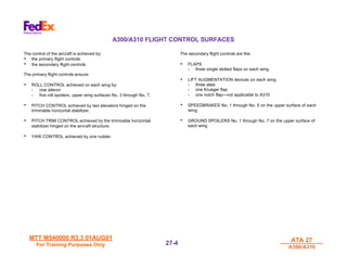
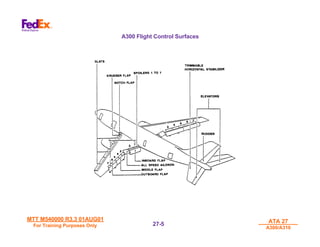
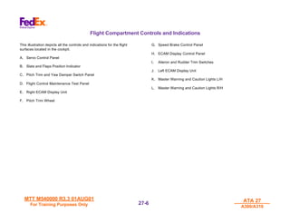
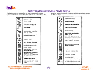
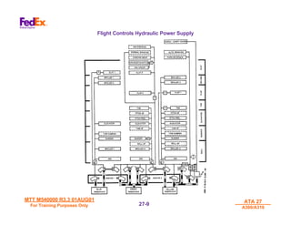
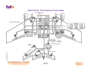
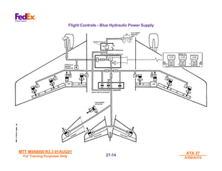
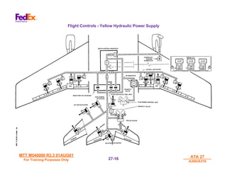
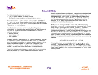
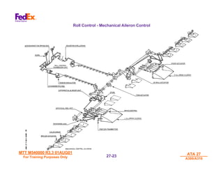
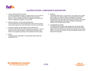
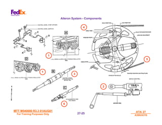
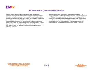
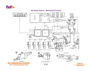
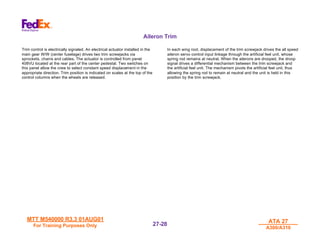
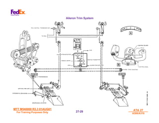
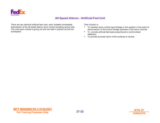
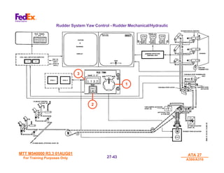
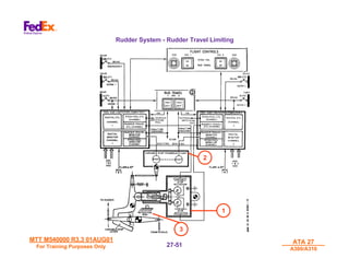
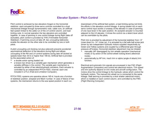
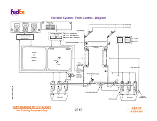
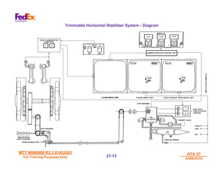
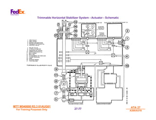
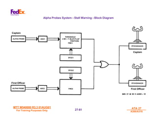
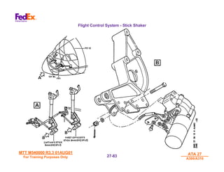
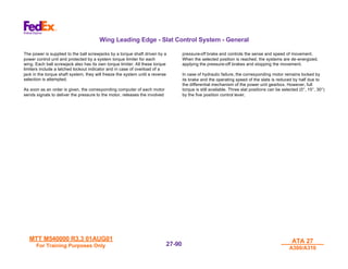
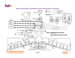
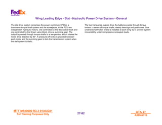
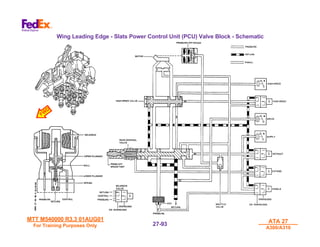
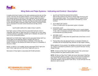
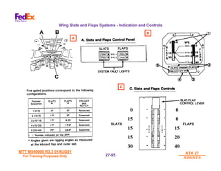
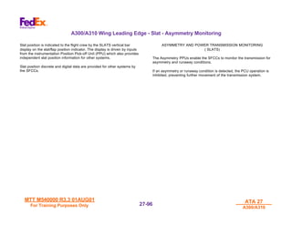
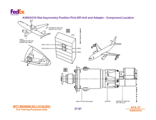
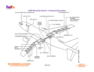
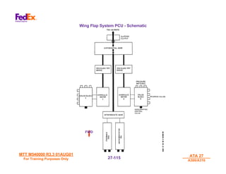
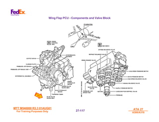
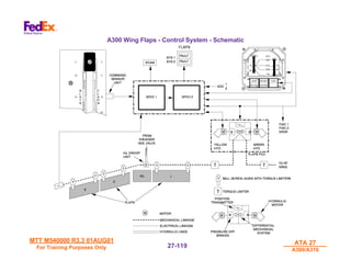
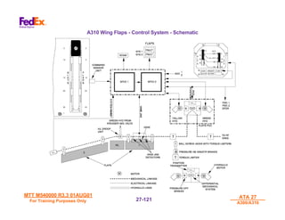
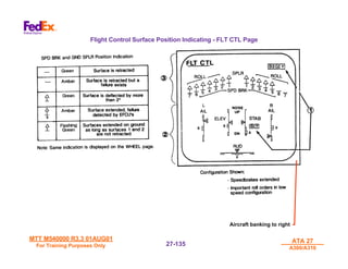
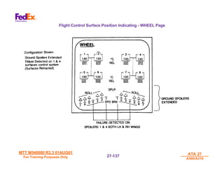
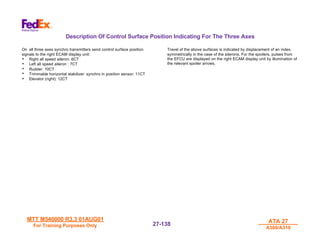
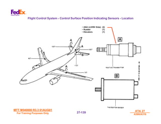
The document provides information about the flight control surfaces and systems for the A300/A310 aircraft. It describes the primary and secondary flight control surfaces that provide roll, pitch, yaw and trim control. These include ailerons, elevators, rudder, flaps, slats and spoilers. It also discusses the three independent hydraulic systems that provide power to the flight controls and can operate the aircraft with two systems failed. Servos, cables, rods and computers are involved in the mechanical and electrical control of the surfaces from the flight deck.


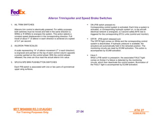


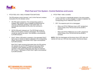
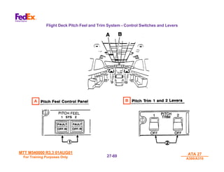


![[NISSAN]_Manual_de_Taller_Nissan_Motor_GA16.pdf](https://cdn.slidesharecdn.com/ss_thumbnails/nissanmanualdetallernissanmotorga16-220509035107-8ddc14af-thumbnail.jpg?width=640&height=640&fit=bounds)


