This document provides an overview and instructions for various features of a Ford vehicle owner's manual. It includes sections on instrumentation, controls, starting the vehicle, driving, roadside emergencies, maintenance, specifications and customer assistance. The introduction notes some symbols that may be seen in the vehicle and contains warnings about exhaust emissions and safety restraints. It also contains copyright information and a table of contents.
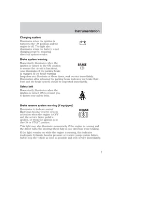


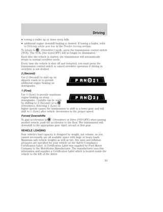
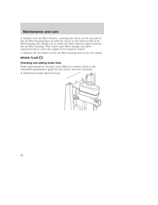
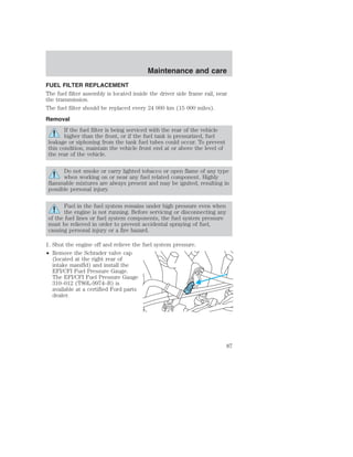
![Maintenance and care
2. When the engine is cool, wrap a thick cloth around the cap. Slowly
turn cap counterclockwise until pressure begins to release.
3. Step back while the pressure releases.
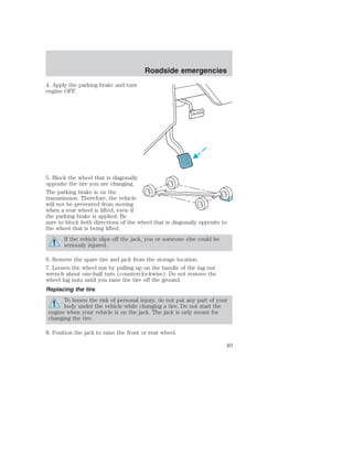
4. When you are sure that all the pressure has been released, use the
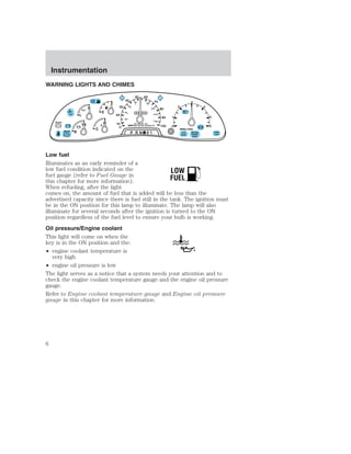
cloth to turn it counterclockwise and remove the cap.
Recycled engine coolant
Ford Motor Company recommends the use of a recycled engine coolant
produced by Ford-approved processes.
Not all coolant recycling processes produce coolant which meets Ford
specification ESE-M97B44-A. Use of a recycled engine coolant which
does not meet the Ford specification may harm engine and cooling
system components.
Always dispose of used automotive fluids in a responsible manner.
Follow your community’s regulations and standards for recycling and
disposing of automotive fluids.
Coolant refill capacity
To find out how much fluid your vehicle’s cooling system can hold, refer
to Refill capacities in the Capacities and specifications chapter.
Fill your engine coolant reservoir as outlined in Adding engine coolant
in this chapter.
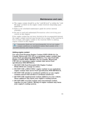
Severe climates
If you drive in extremely cold climates (less than –36° C [–34° F]):
• it may be necessary to increase the coolant concentration
above 50%.
• NEVER increase the coolant concentration above 60%.
• increased engine coolant concentrations above 60% will
decrease the overheat protection characteristics of the engine
coolant and may cause engine damage.
• refer to the chart on the coolant container to ensure the
coolant concentration in your vehicle will provide adequate
freeze protection at the temperatures in which you drive in the
winter months.
67](https://image.slidesharecdn.com/01motorhome-140831143515-phpapp01/85/01-motorhome-67-320.jpg)
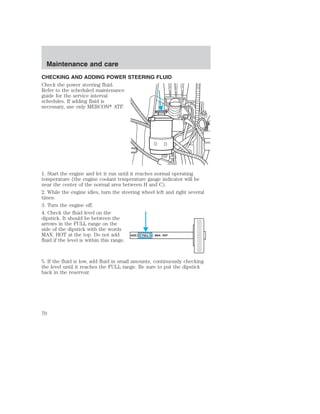
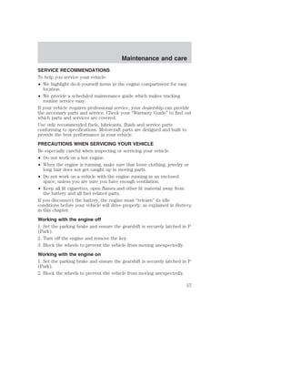
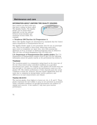
![Maintenance and care
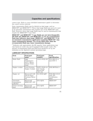
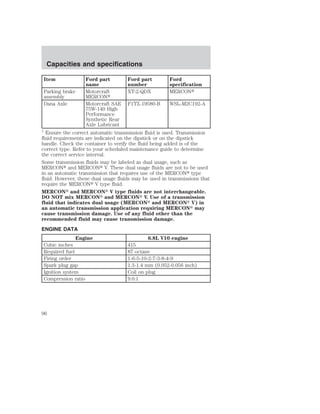
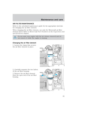
TRANSMISSION FLUID
Checking automatic transmission fluid
Refer to your scheduled maintenance guide for scheduled intervals for
fluid checks and changes. Your transmission does not consume fluid.
However, the fluid level should be checked if the transmission is not
working properly, i.e., if the transmission slips or shifts slowly or if you
notice some sign of fluid leakage.
Automatic transmission fluid expands when warmed. To obtain an
accurate fluid check, drive the vehicle until it is at normal operating
temperature (approximately 30 km [20 miles]). If your vehicle has been
operated for an extended period at high speeds, in city traffic during hot
weather or pulling a trailer, the vehicle should be turned off for about 30
minutes to allow fluid to cool before checking.
1. Drive the vehicle 30 km (20 miles) or until it reaches normal operating
temperature.
2. Park the vehicle on a level surface and engage the parking brake.
3. With the parking brake engaged and your foot on the brake pedal,
start the engine and move the gearshift lever through all of the gear
ranges. Allow sufficient time for each gear to engage.
4. Latch the gearshift lever in P (Park) and leave the engine running.
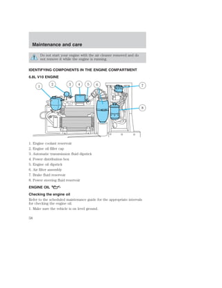
5. Remove the dipstick, wiping it clean with a clean, dry lint free rag. If
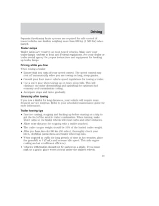
necessary, refer to Identifying components in the engine compartment
in this chapter for the location of the dipstick.
6. Install the dipstick making sure it is fully seated in the filler tube.
7. Remove the dipstick and inspect the fluid level. The fluid should be in
the designated area for normal operating temperature or ambient
temperature.
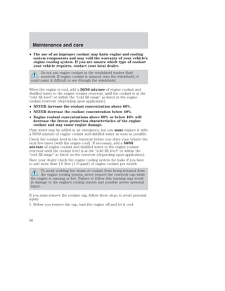
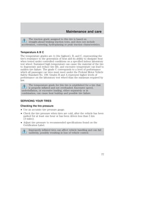
Low fluid level
Do not drive the vehicle if the fluid
level is at the bottom of the dipstick
and the ambient temperature is
above 10°C (50°F).
71](https://image.slidesharecdn.com/01motorhome-140831143515-phpapp01/85/01-motorhome-71-320.jpg)
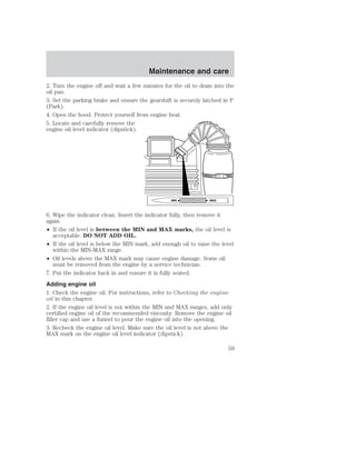
![Maintenance and care
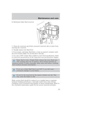
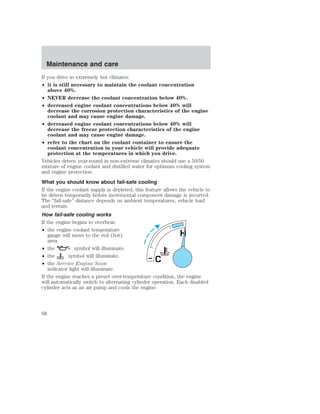
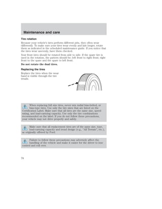
Correct fluid level
The transmission fluid should be checked at normal operating
temperature 66°C-77°C (150°F-170°F) on a level surface. The normal
operating temperature can be reached after approximately 30 km (20
miles) of driving.
You can check the fluid without driving if the ambient temperature is
above 10°C (50°F). However, if fluid is added at this time, an overfill
condition could result when the vehicle reaches normal operating
temperature.
The transmission fluid should be in
this range if at normal operating
temperature (66°C-77°C
[150°F-170°F]).
The transmission fluid should be in
this range if at ambient temperature
(10°C-35°C [50°F-95°F]).
High fluid level
Fluid levels above the safe range
may result in transmission failure.
An overfill condition of transmission
fluid may cause shift and/or
engagement concerns and/or possible damage.
High fluid levels can be caused by an overheating condition.
Adjusting automatic transmission fluid levels
Before adding any fluid, make sure the correct type is used. The type of
fluid used is normally indicated on the dipstick and also in the
Lubricant specifications section in the Capacities and specifications
chapter.
Use of a non-approved automatic transmission fluid may cause
internal transmission component damage.
If necessary, add fluid in 250 mL (1/2 pint) increments through the filler
tube until the level is correct.
If an overfill occurs, excess fluid
should be removed by a qualified
technician.
72](https://image.slidesharecdn.com/01motorhome-140831143515-phpapp01/85/01-motorhome-72-320.jpg)
![5. Follow one of the simple calculations in order to determine fuel
economy:
Multiply liters used by 100, then divide by total kilometers
traveled.
Divide total miles traveled by total gallons used.
Keep a record for at least one month and record the type of driving (city
or highway). This will provide an accurate estimate of the vehicle’s fuel
economy under current driving conditions. Additionally, keeping records
during summer and winter will show how temperature impacts fuel
economy. In general, lower temperatures give lower fuel economy.
Driving style — good driving and fuel economy habits
Give consideration to the lists that follow and you may be able to change
a number of variables and improve your fuel economy.
Habits
• Smooth, moderate operation can yield up to 10% savings in fuel.
• Steady speeds without stopping will usually give the best fuel
economy.
• Idling for long periods of time (greater than one minute) may waste
fuel.
• Anticipate stopping; slowing down may eliminate the need to stop.
• Sudden or hard accelerations may reduce fuel economy.
• Slow down gradually.
• Driving at reasonable speeds (traveling at 88 km/h [55 mph] uses 15%
less fuel than traveling at 105 km/h [65 mph]).
• Revving the engine before turning it off may reduce fuel economy.
• Using the air conditioner or defroster may reduce fuel economy.
• You may want to turn off the speed control in hilly terrain if
unnecessary shifting between third and fourth gear occurs.
Unnecessary shifting of this type could result in reduced fuel
economy.
• Warming up a vehicle on cold mornings is not required and may
reduce fuel economy.
• Resting your foot on the brake pedal while driving may reduce fuel
economy.
Maintenance and care
85](https://image.slidesharecdn.com/01motorhome-140831143515-phpapp01/85/01-motorhome-85-320.jpg)
![Maintenance and care
• Combine errands and minimize stop-and-go driving.
Maintenance
• Keep tires properly inflated and use only recommended size.
• Operating a vehicle with the wheels out of alignment will reduce fuel
economy.
• Use recommended engine oil. Refer to Lubricant Specifications.
• Perform all regularly scheduled maintenance items. Follow the
recommended maintenance schedule and owner maintenance checks
found in your vehicle scheduled maintenance guide.
Conditions
• Heavily loading a vehicle or towing a trailer may reduce fuel economy
at any speed.
• Carrying unnecessary weight may reduce fuel economy (approximately
0.4 km/L [1 mpg] is lost for every 180 kg [400 lb] of weight carried).
• Adding certain accessories to your vehicle (for example bug
deflectors, rollbars/light bars, running boards, ski/luggage racks) may
reduce fuel economy.
• Using fuel blended with alcohol may lower fuel economy.
• Fuel economy may decrease with lower temperatures during the first
12–16 km (8–10 miles) of driving.
• Driving on flat terrain offers improved fuel economy as compared to
driving on hilly terrain.
• Transmissions give their best fuel economy when operated in the top
cruise gear and with steady pressure on the gas pedal.
• Close windows for high speed driving.
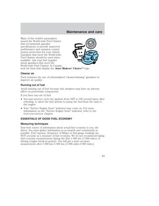
EPA window sticker
Every new vehicle should have the EPA window sticker. Contact your
dealer if the window sticker is not supplied with your vehicle. The EPA
window sticker should be your guide for the fuel economy comparisons
with other vehicles.
It is important to note the box in the lower left corner of the window
sticker. These numbers represent the Range of L/100 km (MPG)
expected on the vehicle under optimum conditions. Your fuel economy
may vary depending upon the method of operation and conditions.
86](https://image.slidesharecdn.com/01motorhome-140831143515-phpapp01/85/01-motorhome-86-320.jpg)