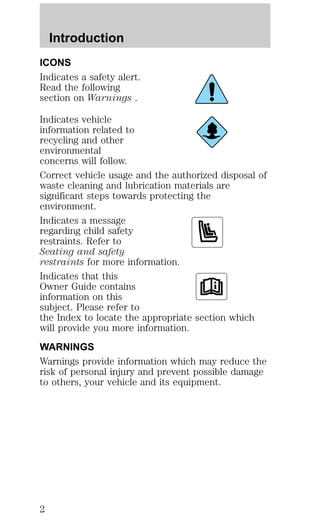
This document provides an overview of the instrumentation, controls, features, and safety systems for a vehicle. It includes descriptions of the various warning lights and gauges that comprise the instrument cluster. Safety icons are defined that indicate important information throughout the owner's manual. Warnings about following break-in procedures for new vehicles and proper operation of safety restraints are also given.

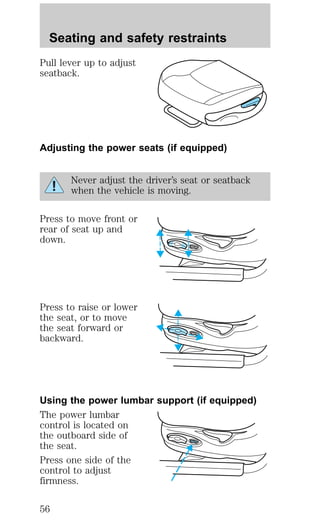
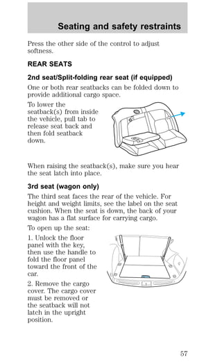
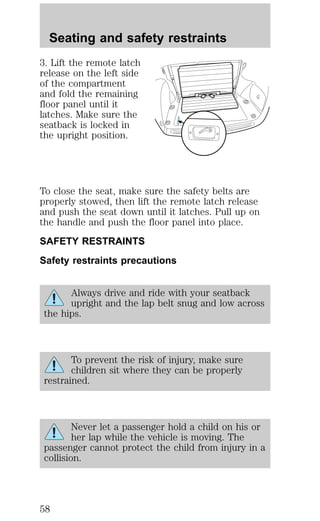
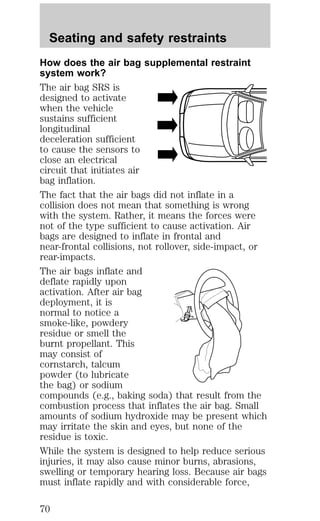
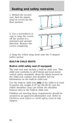
![Seating and safety restraints
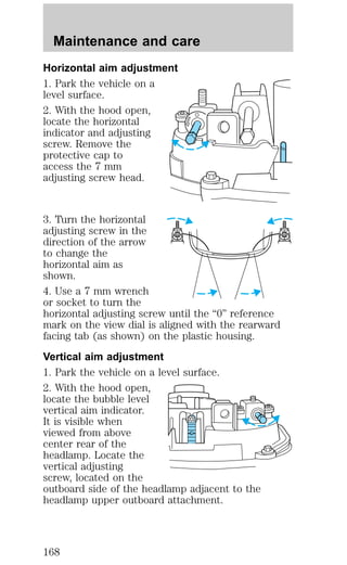
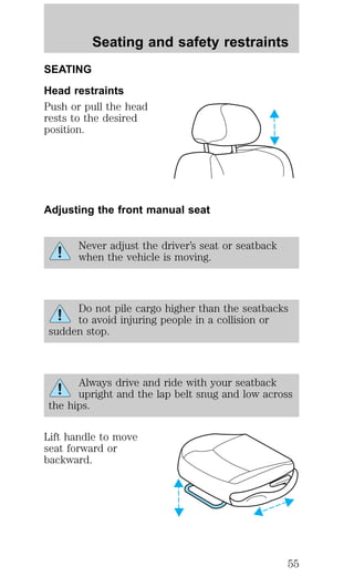
All occupants of the vehicle including the
driver should always properly wear their
safety belts even when air bag SRS is provided.
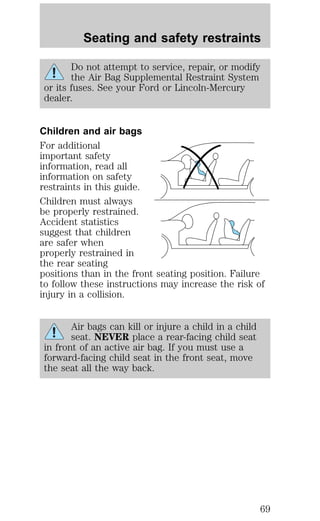
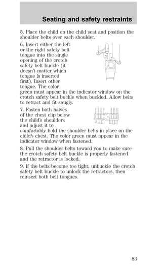
Always transport children 12 years old and
under in the back seat and always use
appropriate child restraints.
NHTSA recommends a minimum distance of
at least 25.4 cm (ten [10] inches) between
an occupant’s chest and the air bag module.
Steps you can take to properly position yourself
away from the airbag:
² Move your seat to the rear as far as you can while
still reaching the pedals comfortably.
² Recline the seat one or two notches from the
upright position.
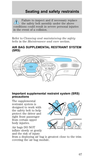
The right front passenger air bag is not
designed to restrain occupants in the center
front seating position.
Do not put anything on or over the air bag
module. Placing objects on or over the air
bag inflation area may cause those objects to be
propelled by the air bag into your face and torso
causing serious injury.
68](https://image.slidesharecdn.com/98taurus-140905151952-phpapp02/85/98-taurus-68-320.jpg)
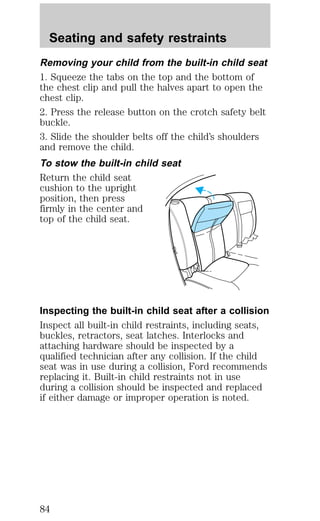
![Seating and safety restraints
Important child restraint precautions
You are required by law to use safety restraints for
children in the U.S. and Canada. If small children
ride in your vehicle (generally children who are four
years old or younger and who weigh 18 kg [40 lbs]
or less), you must put them in safety seats made
especially for children. Check your local and state or
provincial laws for specific requirements regarding
the safety of children in your vehicle.
Never let a passenger hold a child on his or
her lap while the vehicle is moving. The
passenger cannot protect the child from injury in a
collision.
Always follow the instructions and warnings that
come with any infant or child restraint you might
use.
When possible, place children in the rear seat of
your vehicle. Accident statistics suggest that
children are safer when properly restrained in the
rear seating positions than in the front seating
position.
73](https://image.slidesharecdn.com/98taurus-140905151952-phpapp02/85/98-taurus-73-320.jpg)

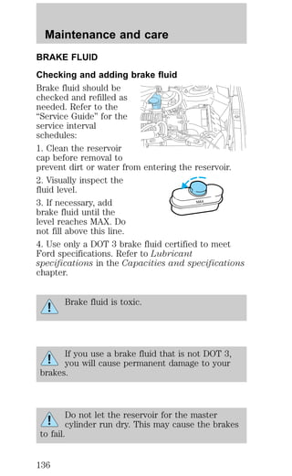
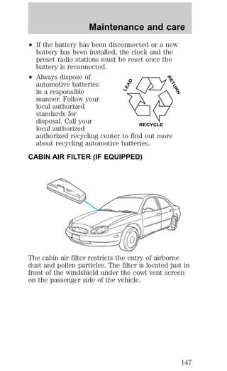
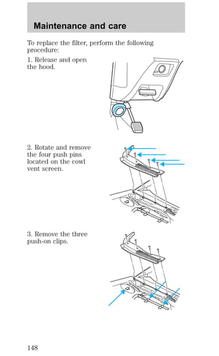
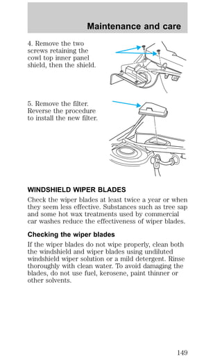
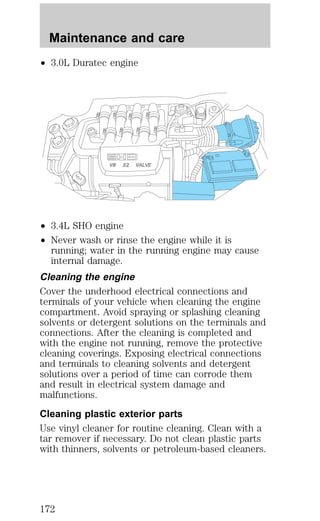
![Maintenance and care
additives in your vehicle. These additives may harm
your engine cooling system. The use of an improper
coolant may void your warranty of your vehicle’s
engine cooling system.
Recycled engine coolant
Ford Motor Company recommends that Ford and
Lincoln-Mercury dealers use recycled engine coolant
produced by Ford-approved processes.
For vehicles with green coolant, not all coolant
recycling processes produce coolant which meets
Ford specification ESE-M97B44–A, and use of such
coolant may harm engine and cooling system
components.
For vehicles with orange coolant, no recycling
process has been approved at this time and use of
such coolant may harm engine and cooling system
components.
Always dispose of used automotive fluids in a
responsible manner. Follow your community’s
regulations and standards for recycling and disposing
of automotive fluids.
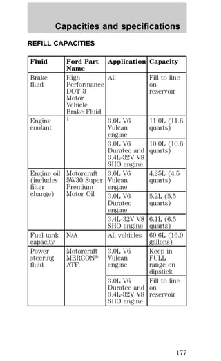
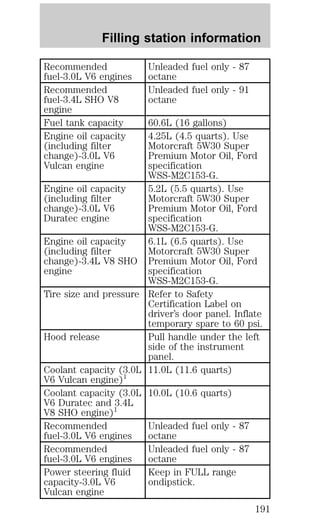
Coolant refill capacity
To find out how much fluid your vehicle’s cooling
system can hold, refer to Refill capacities in the
Capacities and specifications chapter.
Have your dealer check the engine cooling system
for leaks if you have to add more than 1.0 liter (1.0
quart) of engine coolant per month.
Severe winter climate
If you drive in extremely cold climates (less than
–36°C [–34°F]), it may be necessary to increase the
coolant concentration above 50%. Refer to the chart
on the coolant container to ensure the coolant
concentration in your vehicle is such that the
coolant will not freeze at the temperature level in
which you drive during winter months. Never
140](https://image.slidesharecdn.com/98taurus-140905151952-phpapp02/85/98-taurus-140-320.jpg)
![Maintenance and care
5. If the fluid is low, add fluid in small amounts,
continuously checking the level until it reaches the
FULL HOT range. Be sure to put the dipstick back
in the reservoir.
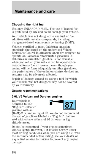
3.0L Duratec engine and 3.4L SHO engine
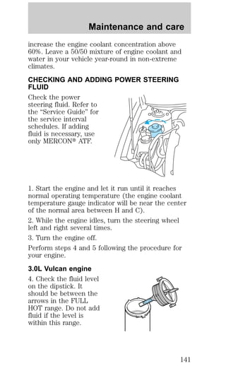
4. Check the fluid level
in the reservoir. It
should be between the
MIN and MAX lines. Do
not add fluid if the
MAX
MIN
level is within this
range.
5. If the fluid is low, add fluid in small amounts,
continuously checking the level until it reaches the
range between the MIN and MAX lines. Be sure to
put the cap back on the reservoir.
TRANSMISSION FLUID
Checking automatic transmission fluid
Refer to your “Service Guide” for scheduled intervals
for fluid checks and changes. Your transaxle does
not consume fluid. However, the fluid level should
be checked if the transaxle is not working properly,
i.e., if the transaxle slips or shifts slowly or if you
notice some sign of fluid leakage.
Automatic transmission fluid expands when
warmed. To obtain an accurate fluid check,
drive the vehicle until it is warmed up
(approximately 30 km [20 miles]). If your
vehicle has been operated for an extended
period at high speeds, in city traffic during hot
weather or pulling a trailer, the vehicle should
be turned off for about 30 minutes to allow
fluid to cool before checking.
1. Drive the vehicle 30 km (20 miles) or until it
reaches normal operating temperature.
142](https://image.slidesharecdn.com/98taurus-140905151952-phpapp02/85/98-taurus-142-320.jpg)
![Maintenance and care
2. Park the vehicle on a level surface and engage the
parking brake.
3. With the parking brake engaged and your foot on
the brake pedal, start the engine and move the
gearshift lever through all of the gear ranges. Allow
sufficient time for each gear to engage.
4. Latch the gearshift lever in P (Park) and leave the
engine running.
5. Remove the dipstick, wiping it clean with a clean,
dry lint free rag.
6. Install the dipstick making sure it is fully seated in
the filler tube.
7. Remove the dipstick and inspect the fluid level.
The fluid should be in the designated areas for
normal and room temperature.
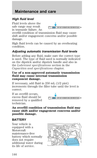
Low fluid level
Do not drive the
vehicle if the fluid level
DON’T ADD IF IN CROSSHATCH AREA--CHECH WHEN HOT-IDLING
is at the bottom of the
dipstick and the outside temperatures are above
10°C (50°F).
Correct fluid level
The transmission fluid should be checked at normal
operating temperatures 66°C-77°C (150°F-170°F) on
a level surface. The normal operating temperature
can be reached after approximately 30 km (20
miles) of driving.
The transmission fluid
should be in this range
DON’T ADD IF IN CROSSHATCH AREA--CHECH WHEN HOT-IDLING
if at normal operating
temperature (66°C-77°C [150°F-170°F]).
143](https://image.slidesharecdn.com/98taurus-140905151952-phpapp02/85/98-taurus-143-320.jpg)