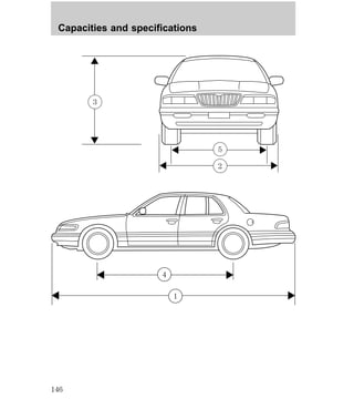
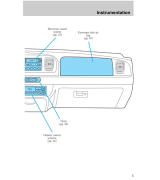
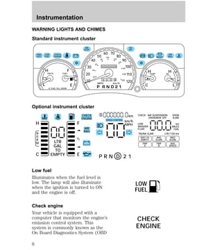
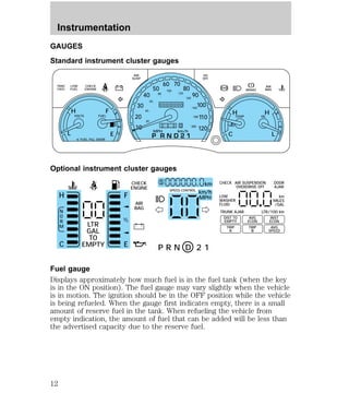
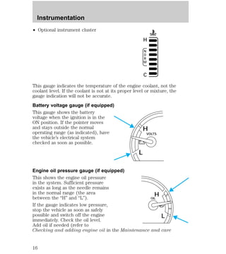
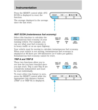
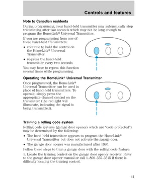
The document provides an overview of instrumentation and gauges for a vehicle. It describes in detail the various dashboard lights, gauges, and controls including what they indicate and their functions. Warnings are provided for certain light indications that require immediate attention. Measurements can be switched between metric and English units on the optional instrument cluster.


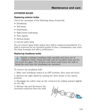
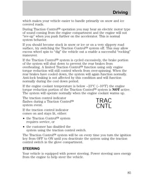
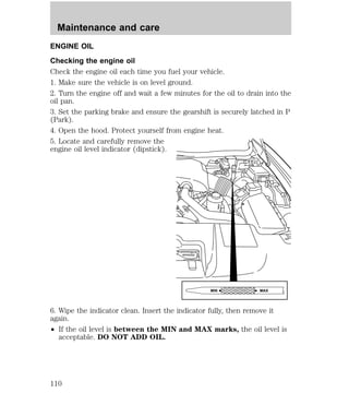
![2. Press and hold the COMP side of
the control for approximately six
seconds until “C” appears in the
mirror display.
3. Drive the vehicle slowly (less
than 5 km/h [3 mph]) in circles or
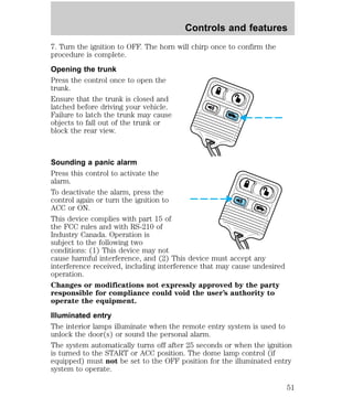
on your everyday routine until the
display reads a direction.
4. The compass is now calibrated.
TRUNK REMOTE CONTROL
The remote trunk release control is
located on the driver’s door trim
panel and can be operated at any
time.
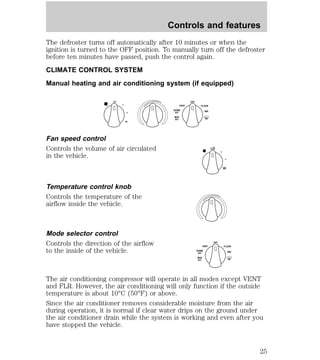
Controls and features
COMP MIRROR
NW
TRUNK
45](https://image.slidesharecdn.com/98grandmarquis-140905151943-phpapp02/85/98-grand-marquis-45-320.jpg)


![Seating and safety restraints
AIR BAG SUPPLEMENTAL RESTRAINT SYSTEM (SRS)
30
20
40
AM FM
FM1 ST
CLK
BASS TREB BAL FADE
TAPE
AMS
f w DOLBY B NR
SCAN EJ FF
REW
SIDE 1-2
CD
1 2 3 4 5 6
OFF F
AUTO
VOL - PUSH ON
SEEK
TUNE
OUTSIDE TEMP AUTOMATIC
ON
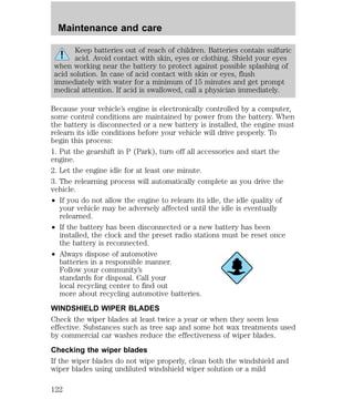
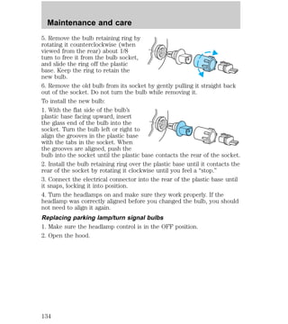
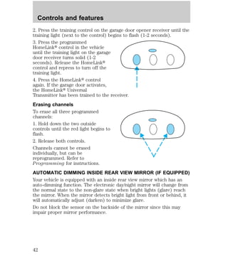
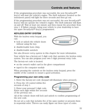
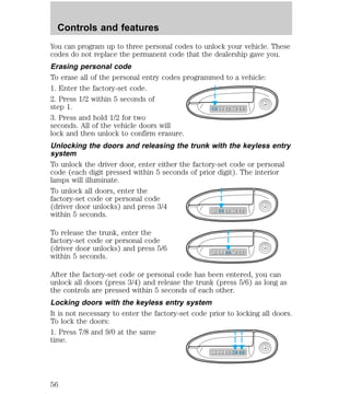
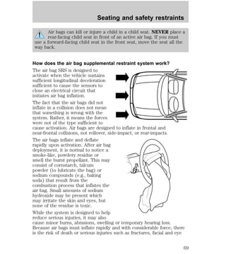
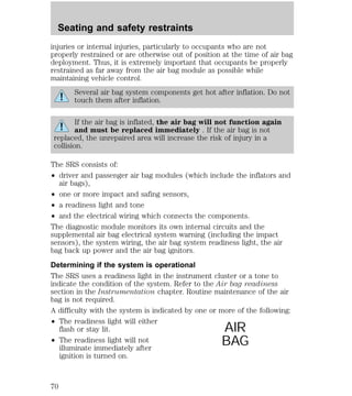
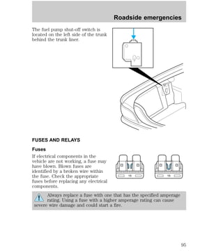
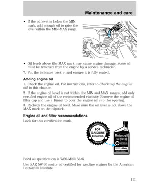
Important supplemental restraint system (SRS) precautions
The supplemental restraint system
is designed to work with the safety
belt to help protect the driver and
right front passenger from certain
upper body injuries.
Air bags DO NOT inflate slowly or
gently and the risk of injury from a
deploying air bag is greatest close to
the trim covering the air bag
module.
All occupants of the vehicle including the driver should always
properly wear their safety belts even when air bag SRS is
provided.
Always transport children 12 years old and under in the back
seat and always use appropriate child restraints.
NHTSA recommends a minimum distance of at least 25.4 cm
(ten [10] inches) between an occupant’s chest and the air bag
module.
HI
LO
F
S
OFF
E
CHECK
ENGINE
AIR
SUSP
OD
OFF
BRAKE
VOLTS FUEL TEMP OIL
MPH km/h
10
40
50
60 70
80
90
100
110
120
20
60
80
100
120
140
160
180
200
H H
C L
H F
L
< FUEL FILL DOOR
NORM A/C VENT FLOOR FLR • DEF DEF
HI
LO MAX A/C
R.DEF.
AUTO
LAMP
0FF
PANEL
DIM
PUSH INTERIOR
H M
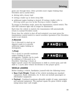
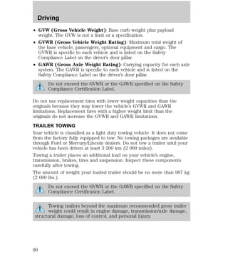
P R N D 2 1
OFF
RSM
SET
ACC
COAST
10:35
67](https://image.slidesharecdn.com/98grandmarquis-140905151943-phpapp02/85/98-grand-marquis-67-320.jpg)

![Seating and safety restraints
² A series of five beeps will be heard. The tone pattern will repeat
periodically until the problem and light are repaired.
If any of these things happen, even intermittently, have the SRS serviced
at your dealership or by a qualified technician immediately. Unless
serviced, the system may not function properly in the event of a
collision.
Disposal of air bags and air bag equipped vehicles
For disposal of air bags or air bag equipped vehicles, see your local
dealership or qualified technician. Air bags MUST BE disposed of by
qualified personnel.
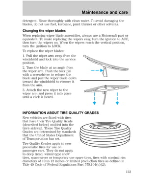
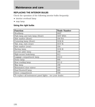
SAFETY RESTRAINTS FOR CHILDREN
Important child restraint precautions
You are required by law to use safety restraints for children in the U.S.
and Canada. If small children ride in your vehicle (generally children who
are four years old or younger and who weigh 18 kg [40 lbs] or less), you
must put them in safety seats made especially for children. Check your
local and state or provincial laws for specific requirements regarding the
safety of children in your vehicle.
Never let a passenger hold a child on his or her lap while the
vehicle is moving. The passenger cannot protect the child from
injury in a collision.
Always follow the instructions and warnings that come with any infant or
child restraint you might use.
When possible, place children in the rear seat of your vehicle. Accident
statistics suggest that children are safer when properly restrained in the
rear seating positions than in the front seating position.
Children and safety belts
Children who are too large for child safety seats (as specified by your
child safety seat manufacturer) should always wear safety belts.
Follow all the important safety restraint and air bag precautions that
apply to adult passengers in your vehicle.
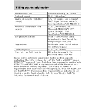
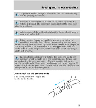
If the shoulder belt portion of a combination lap and shoulder belt can
be positioned so it does not cross or rest in front of the child’s face or
71](https://image.slidesharecdn.com/98grandmarquis-140905151943-phpapp02/85/98-grand-marquis-71-320.jpg)


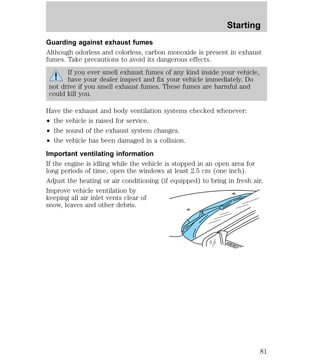

![Severe winter climate
If you drive in extremely cold climates (less than –36°C [–34°F]), it may
be necessary to increase the coolant concentration above 50%. Refer to
the chart on the coolant container to ensure the coolant concentration in
your vehicle is such that the coolant will not freeze at the temperature
level in which you drive during winter months. Never increase the engine
coolant concentration above 60%. Leave a 50/50 mixture of engine
coolant and water in your vehicle year-round in non-extreme climates.
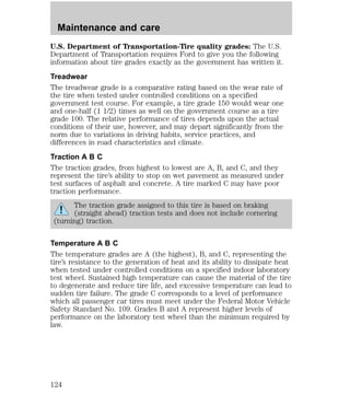
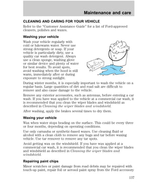
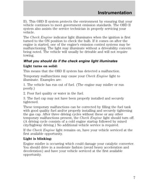
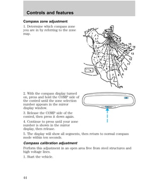
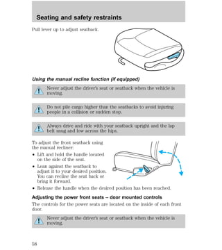
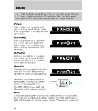
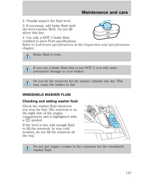
How fail-safe cooling works
² Standard cluster
² Optional cluster
H
H
If the engine overheats, the engine will automatically switch to
alternating cylinder operation. Each disabled cylinder acts as an air
pump and cools the engine.
When this occurs:
² if your vehicle is equipped with analog gauges, the engine coolant
temperature gauge will move to the H (hot) area
TEMP
C
NORM
C
Maintenance and care
116](https://image.slidesharecdn.com/98grandmarquis-140905151943-phpapp02/85/98-grand-marquis-116-320.jpg)
![Maintenance and care
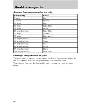
TRANSMISSION FLUID
Checking and adding automatic transmission fluid
Follow the scheduled service intervals outlined in the “Service Guide.”
Before adding any fluid, make sure the correct type is used. The type of
fluid used is normally indicated on the dipstick and/or dipstick handle
and also in the Lubricant specifications section in the Capacities and
specifications chapter.
An overfill condition of transmission fluid may cause shift and/or
engagement concerns and/or possible damage.
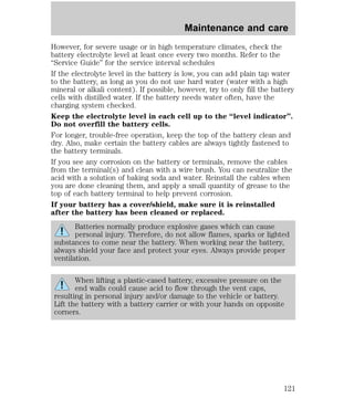
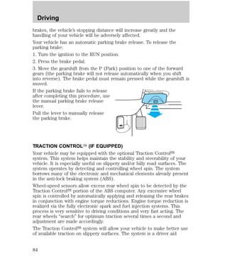
Do not drive the vehicle if the fluid
level is below the bottom hole on
the dipstick and outside
DON’T ADD
temperatures are above 10°C (50°F)
(see figure to the right).
Your transmission does not use up fluid. However, it is recommended
that you check the transmission fluid at least twice a year. The fluid level
should be checked if the transmission is not working properly, i.e., if the
transmission slips or shifts slowly or if you notice some sign of fluid
leakage.
Transmission fluid should be checked at normal operating temperatures
66°C-77°C (150°F-170°F) on a level surface. The normal operating
temperature can be reached after approximately 32 km (20 miles) of
driving.
The transmission fluid should be in
this range if at normal operating
temperature (66°C-77°C
DON’T ADD
[150°F-170°F]) (see figure to the
right).
The transmission fluid should be in
this range if at room temperature
(10°C-35°C [50°F-95°F]) (see figure
DON’T ADD
to the right).
If your vehicle has been operated for an extended period at high speeds,
in city traffic during hot weather or pulling a trailer, the vehicle should
be turned off for about 30 minutes to allow the fluid to cool before
checking.
1. Park the vehicle on a level surface and engage the parking brake.
119](https://image.slidesharecdn.com/98grandmarquis-140905151943-phpapp02/85/98-grand-marquis-119-320.jpg)