This document provides an overview of instrumentation, controls, features, and gauges for a vehicle. It includes descriptions and pictures to explain the function of different buttons, knobs, and displays including the instrument cluster, headlight control, climate control, audio system, warning lights, and vehicle gauges like the speedometer and fuel gauge. It also provides information on starting and driving the vehicle safely as well as maintenance and care.


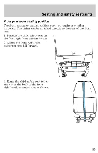
![Seating and safety restraints
section in the Instrumentation chapter. Routine maintenance of the air
bag is not required.
A difficulty with the system is indicated by one or more of the following:
² The readiness light will either
flash or stay lit.
² The readiness light will not
illuminate immediately after
ignition is turned on.
² A series of five beeps will be heard. The tone pattern will repeat
periodically until the problem and light are repaired.
If any of these things happen, even intermittently, have the SRS serviced
at your dealership or by a qualified technician immediately. Unless
serviced, the system may not function properly in the event of a
collision.
Disposal of air bags and air bag equipped vehicles
For disposal of air bags or air bag equipped vehicles, see your local
dealership or qualified technician. Air bags MUST BE disposed of by
qualified personnel.
SAFETY RESTRAINTS FOR CHILDREN
Important child restraint precautions
You are required by law to use safety restraints for children in the U.S.
and Canada. If small children ride in your vehicle (generally children who
are four years old or younger and who weigh 18 kg [40 lbs] or less), you
must put them in safety seats made especially for children. Check your
local and state or provincial laws for specific requirements regarding the
safety of children in your vehicle.
Never let a passenger hold a child on his or her lap while the
vehicle is moving. The passenger cannot protect the child from
injury in a collision.
Always follow the instructions and warnings that come with any infant or
child restraint you might use.
When possible, place children in the rear seat of your vehicle. Accident
statistics suggest that children are safer when properly restrained in the
rear seating positions than in the front seating position.
49](https://image.slidesharecdn.com/98e150-250-350-450-140905151935-phpapp01/85/98-e150-250-350-450-49-320.jpg)


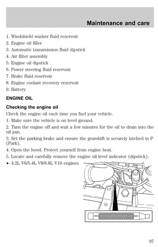


![Maintenance and care
Do not use alcohol or methanol antifreeze or any engine coolants mixed
with alcohol or methanol antifreeze. Do not use supplemental coolant
additives in your vehicle. These additives may harm your engine cooling
system. The use of an improper coolant may void your warranty of your
vehicle’s engine cooling system.
Recycled engine coolant
Ford Motor Company recommends that Ford and Lincoln-Mercury
dealers use recycled engine coolant produced by Ford-approved
processes. Not all coolant recycling processes produce coolant which
meets Ford specification ESE-M97B44–A, and use of such coolant may
harm engine and cooling system components.
Always dispose of used automotive fluids in a responsible manner.
Follow your community’s regulations and standards for recycling and
disposing of automotive fluids.
Coolant refill capacity
To find out how much fluid your vehicle’s cooling system can hold, refer
to Refill capacities in the Capacities and specifications chapter.
Have your dealer check the engine cooling system for leaks if you have
to add more than a liter (quart) of engine coolant per month.
Severe winter climate
If you drive in extremely cold climates (less than –36°C [–34°F]), it may
be necessary to increase the coolant concentration above 50%. Refer to
the chart on the coolant container to ensure the coolant concentration in
your vehicle is such that the coolant will not freeze at the temperature
level in which you drive during winter months. Never increase the engine
coolant concentration above 60%. Leave a 50/50 mixture of engine
coolant and water in your vehicle year-round in non-extreme climates.
What you should know about fail-safe cooling (if equipped)
If the engine coolant supply is depleted, this feature allows the vehicle to
be driven temporarily before incremental component damage is incurred.
The “fail safe” distance depends on ambient temperatures, vehicle load
and terrain.
103](https://image.slidesharecdn.com/98e150-250-350-450-140905151935-phpapp01/85/98-e150-250-350-450-103-320.jpg)


![Maintenance and care
TRANSMISSION FLUID
Checking and adding automatic transmission fluid
Follow the scheduled service intervals outlined in the “Service Guide”.
Before adding any fluid, make sure the correct type is used. The type of
fluid used is normally indicated on the dipstick and/or dipstick handle
and also in the Lubricant specifications section in the Capacities and
specifications chapter.
An overfill condition of transmission fluid may cause shift and/or
engagement concerns and/or possible damage.
Do not drive the vehicle if the fluid
level is below the COLD (C) area on
the dipstick and outside
temperatures are above 10°C (50°F)
(see figure to the right).
Your transmission does not use up fluid. However, it is recommended
that you check the transmission fluid at least twice a year. The fluid level
should be checked if the transmission is not working properly, i.e., if the
transmission slips or shifts slowly or if you notice some sign of fluid
leakage.
Transmission fluid should be checked at normal operating temperatures
66°C-77°C (150°F-170°F) on a level surface. The normal operating
temperature can be reached after approximately 32 km (20 miles) of
driving.
The transmission fluid should be in
this range if at normal operating
temperature (66°C-77°C
[150°F-170°F]) (see figure to the
right).
The transmission fluid should be in
this range if at room temperature
(10°C-35°C [50°F-95°F]) (see figure
to the right).
If your vehicle has been operated for an extended period at high speeds,
in city traffic during hot weather or pulling a trailer, the vehicle should
be turned off for about 30 minutes to allow the fluid to cool before
checking.
1. Park the vehicle on a level surface and engage the parking brake.
106](https://image.slidesharecdn.com/98e150-250-350-450-140905151935-phpapp01/85/98-e150-250-350-450-106-320.jpg)