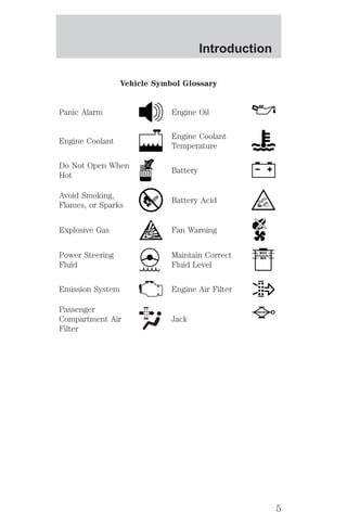
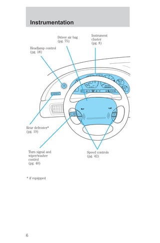
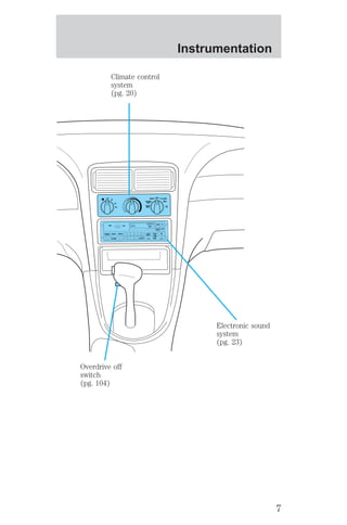
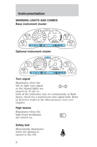
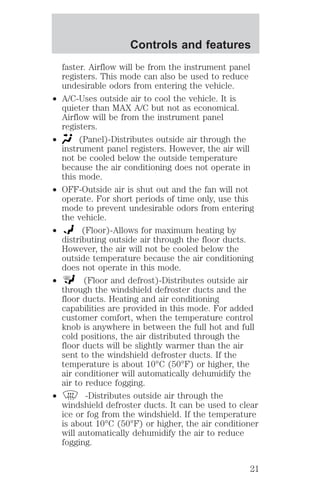
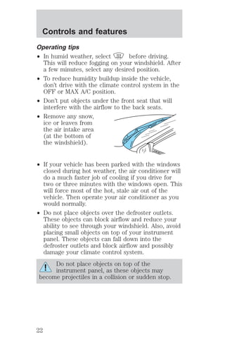
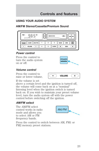
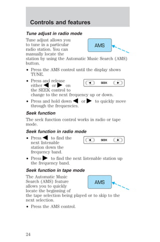
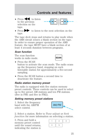
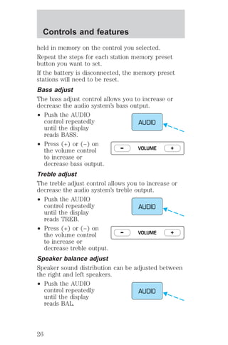
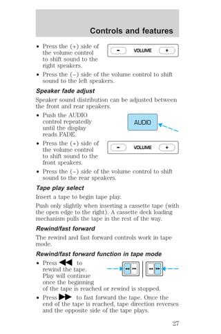
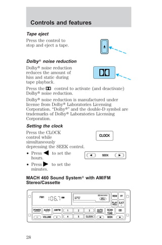
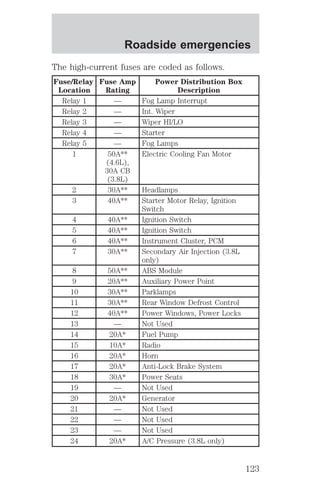
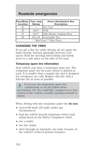
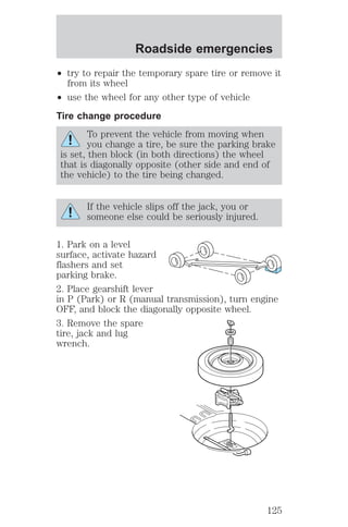
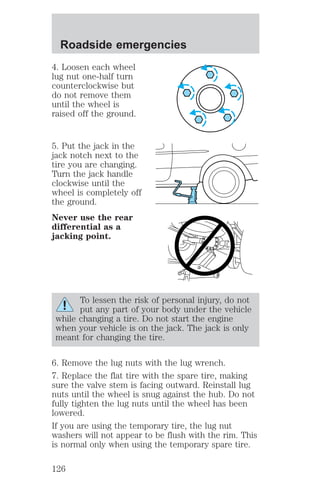
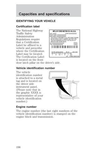
The document describes the instrumentation and controls of a vehicle. It includes diagrams and explanations of the instrument cluster, warning lights, gauges, controls, and features. Safety information and operating instructions are provided for many vehicle systems.

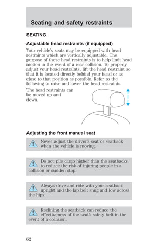
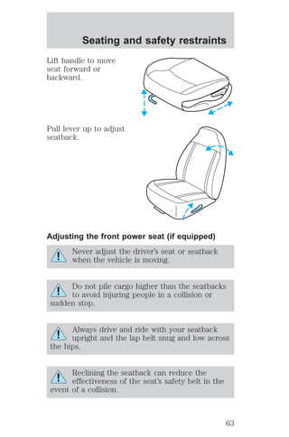
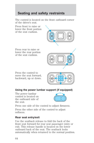
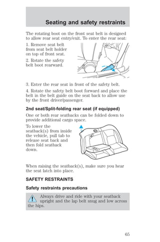
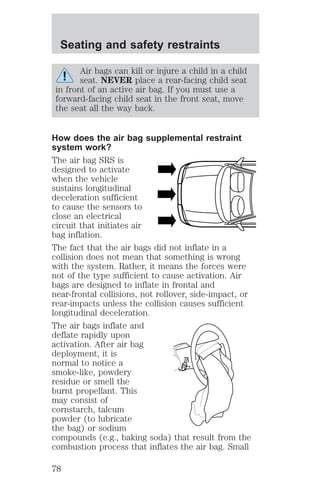
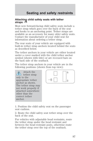
![Seating and safety restraints
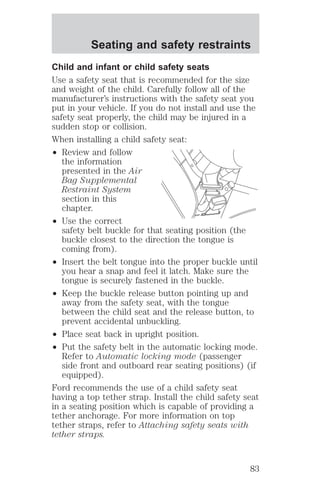
Important child restraint precautions
You are required by law to use safety restraints for
children in the U.S. and Canada. If small children
ride in your vehicle (generally children who are four
years old or younger and who weigh 18 kg [40 lbs]
or less), you must put them in safety seats made
especially for children. Check your local and state or
provincial laws for specific requirements regarding
the safety of children in your vehicle.
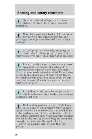
Never let a passenger hold a child on his or
her lap while the vehicle is moving. The
passenger cannot protect the child from injury in a
collision.
Always follow the instructions and warnings that
come with any infant or child restraint you might
use.
When possible, always place children under age 12
in the rear seat of your vehicle. Accident statistics
suggest that children are safer when properly
restrained in the rear seating positions than in the
front seating position.
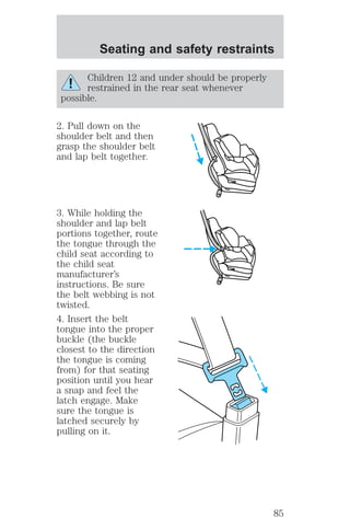
Children and safety belts
If the child is the proper size, restrain the child in a
safety seat.
Children who are too large for child safety seats (as
specified by your child safety seat manufacturer)
should always wear safety belts.
Follow all the important safety restraint and air bag
precautions that apply to adult passengers in your
vehicle.
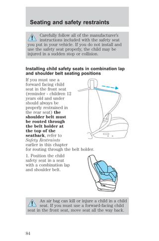
If the shoulder belt portion of a combination lap and
shoulder belt can be positioned so it does not cross
or rest in front of the child’s face or neck, the child
should wear the lap and shoulder belt. Moving the
child closer to the center of the vehicle may help
provide a good shoulder belt fit.
81](https://image.slidesharecdn.com/00mustang-140904144527-phpapp02/85/00-mustang-81-320.jpg)
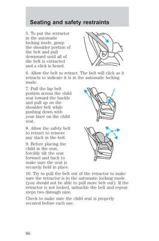
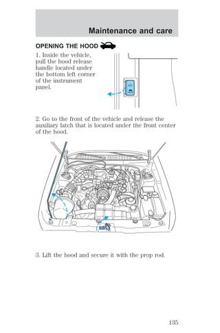
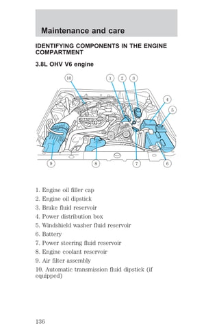
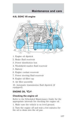
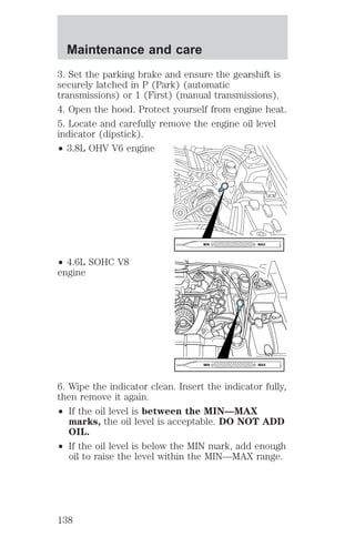
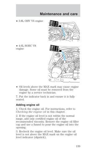
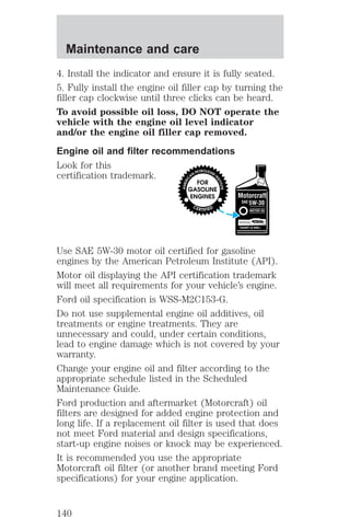
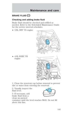
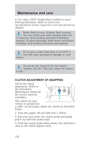
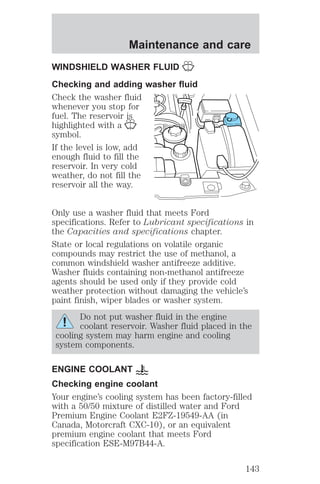
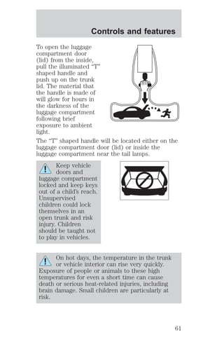
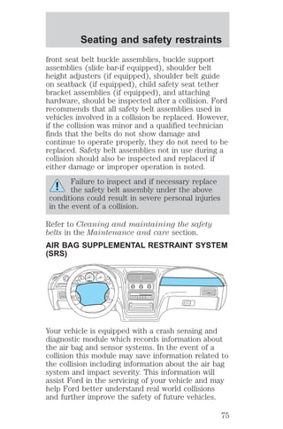
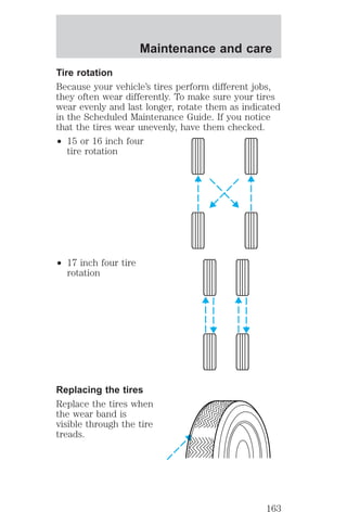
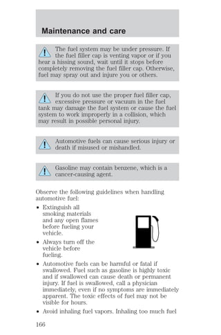
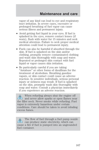
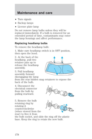
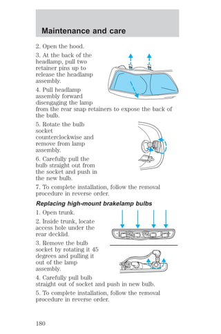
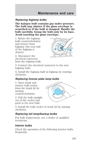
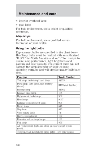
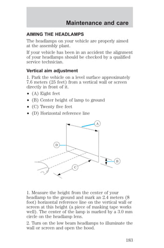
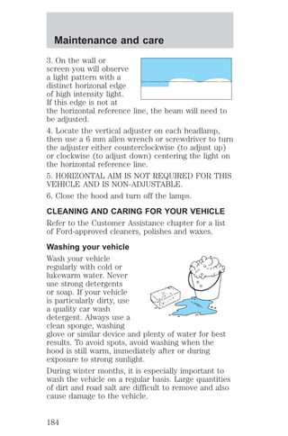
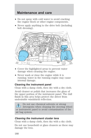
![Maintenance and care
9. Check the coolant level in the reservoir before
you drive your vehicle the next few times (with the
engine cool).
10. If necessary, add a 50/50 mixture of engine
coolant and distilled water to the engine coolant
reservoir until the coolant level is at the “cold fill
level” as listed on the reservoir.
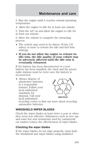
Recycled engine coolant
Ford Motor Company recommends the use of a
recycled engine coolant produced by Ford-approved
processes.
Not all coolant recycling processes produce coolant
which meets Ford specification ESE-M97B44-A. Use
of a recycled engine coolant which does not meet
the Ford specification may harm engine and cooling
system components.
Always dispose of used automotive fluids in a
responsible manner. Follow your community’s
regulations and standards for recycling and disposing
of automotive fluids.
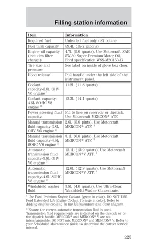
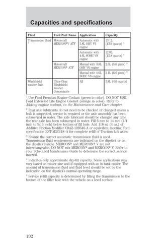
Coolant refill capacity
To find out how much fluid your vehicle’s cooling
system can hold, refer to Refill capacities in the
Capacities and specifications chapter.
Fill your engine coolant reservoir as outlined in
Adding engine coolant in this chapter.
Severe climates
If you drive in extremely cold climates (less than
–36° C [–34° F]):
² it may be necessary to increase the coolant
concentration above 50%.
² NEVER increase the coolant concentration
above 60%.
² increased engine coolant concentrations
above 60% will decrease the overheat
150](https://image.slidesharecdn.com/00mustang-140904144527-phpapp02/85/00-mustang-150-320.jpg)
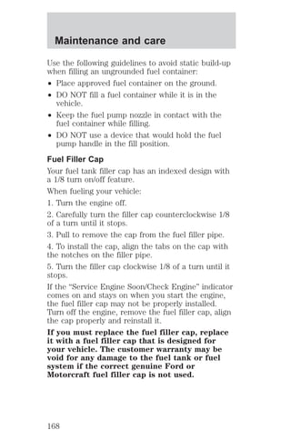
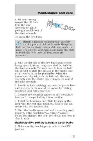
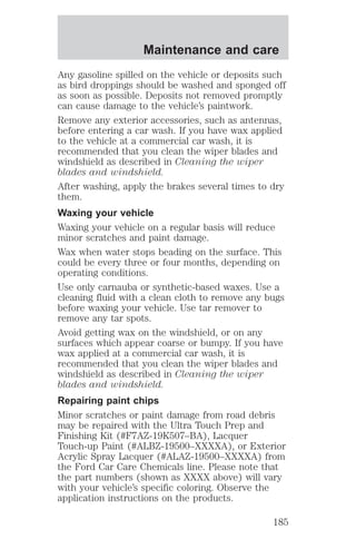
![Maintenance and care
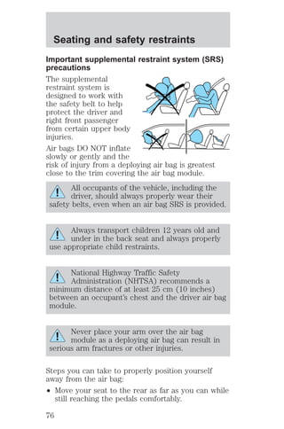
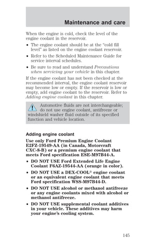
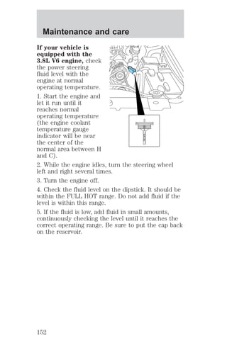
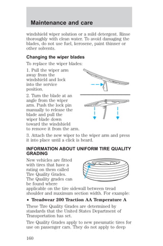
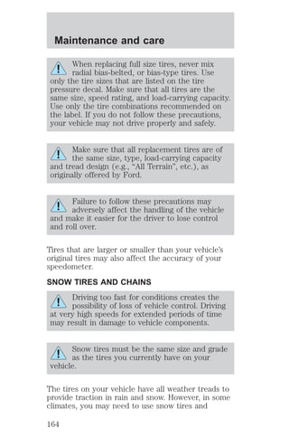
If your vehicle is
equipped with a 4.6L
V8 engine, check the
power steering fluid
level with the engine at
ambient temperature.
Allow at least one-half
hour after driving for
the power steering
fluid to cool.
1. Start the engine and
allow the engine to
idle.
MAX
2. Turn the steering
MIN
wheel left and right
several times.
3. Turn the engine off.
4. Check the fluid level in the reservoir. It should be
between the MIN and MAX lines. Do not add fluid if
the level is within this range.
5. If the fluid is low, add fluid in small amounts,
continuously checking the level until it reaches the
correct operating range. Be sure to put the cap back
on the reservoir.
TRANSMISSION FLUID
Checking automatic transmission fluid
Refer to your Scheduled Maintenance Guide for
scheduled intervals for fluid checks and changes.
Your transmission does not consume fluid. However,
the fluid level should be checked if the transmission
is not working properly, i.e., if the transmission slips
or shifts slowly or if you notice some sign of fluid
leakage.
Automatic transmission fluid expands when warmed.
To obtain an accurate fluid check, drive the vehicle
until it is at normal operating temperature
(approximately 30 km [20 miles]). If your vehicle has
153](https://image.slidesharecdn.com/00mustang-140904144527-phpapp02/85/00-mustang-153-320.jpg)
![Maintenance and care
You can check the fluid without driving if the
ambient temperature is above 10°C (50°F). However,
if fluid is added at this time, an overfill condition
could result when the vehicle reaches normal
operating temperature.
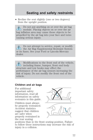
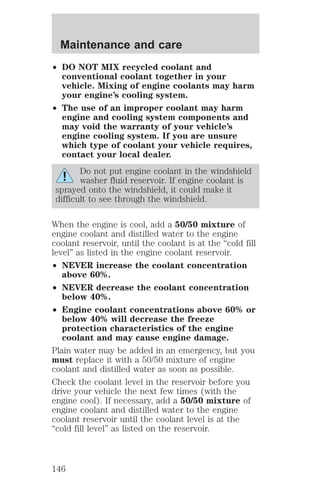
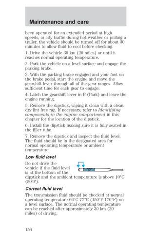
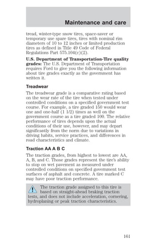
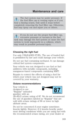
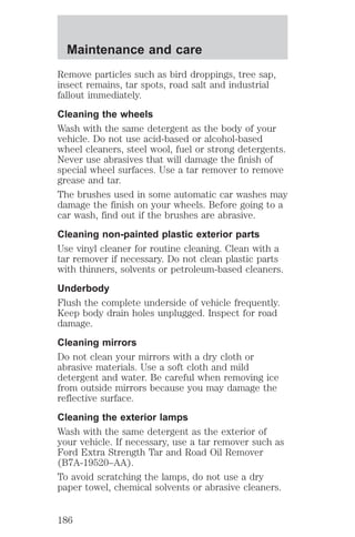
The transmission fluid
should be in this range
if at normal operating
temperature (66°C-77°C [150°F-170°F]).
The transmission fluid
should be in this range
if at ambient
temperature (10°C-35°C [50°F-95°F]).
High fluid level
Fluid levels above the
safe range may result
in transmission failure.
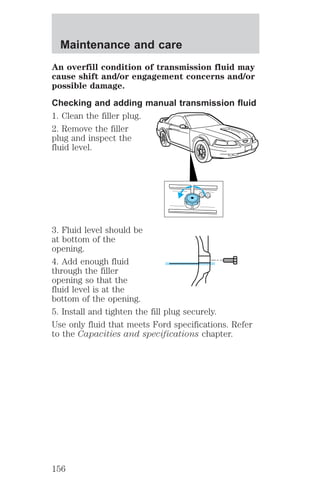
An overfill condition of transmission fluid may cause
shift and/or engagement concerns and/or possible
damage.
High fluid levels can be caused by an overheating
condition.
Adjusting automatic transmission fluid levels
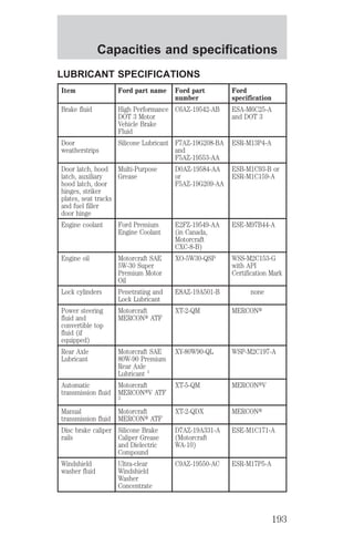
Before adding any fluid, make sure the correct type
is used. The type of fluid used is normally indicated
on the dipstick and also in the Lubricant
specifications section in the Capacities and
specifications chapter.
Use of a non-approved automatic transmission
fluid may cause internal transmission
component damage.
If necessary, add fluid in 250 mL (1/2 pint) increments
through the filler tube until the level is correct.
If an overfill occurs,
excess fluid should be
removed by a qualified
technician.
155](https://image.slidesharecdn.com/00mustang-140904144527-phpapp02/85/00-mustang-155-320.jpg)
![Maintenance and care
4. Subtract your initial odometer reading from the
current odometer reading.
5. Follow one of the simple calculations in order to
determine fuel economy:
Multiply liters used by 100, then divide by total
kilometers traveled.
Divide total miles traveled by total gallons
used.
Keep a record for at least one month and record the
type of driving (city or highway). This will provide
an accurate estimate of the vehicle’s fuel economy
under current driving conditions. Additionally,
keeping records during summer and winter will show
how temperature impacts fuel economy. In general,
lower temperatures give lower fuel economy.
Driving style — good driving and fuel economy
habits
Give consideration to the lists that follow and you
may be able to change a number of variables and
improve your fuel economy.
Habits
² Smooth, moderate operation can yield up to 10%
savings in fuel.
² Steady speeds without stopping will usually give
the best fuel economy.
² Idling for long periods of time (greater than one
minute) may waste fuel.
² Anticipate stopping; slowing down may eliminate
the need to stop.
² Sudden or hard accelerations may reduce fuel
economy.
² Slow down gradually.
² Driving at reasonable speeds (traveling at 88 km/h
[55 mph] uses 15% less fuel than traveling at 105
km/h [65 mph]).
173](https://image.slidesharecdn.com/00mustang-140904144527-phpapp02/85/00-mustang-173-320.jpg)
![Maintenance and care
² Revving the engine before turning it off may
reduce fuel economy.
² Using the air conditioner or defroster may reduce
fuel economy.
² You may want to turn off the speed control in
hilly terrain if unnecessary shifting between third
and fourth gear occurs. Unnecessary shifting of
this type could result in reduced fuel economy.
² Warming up a vehicle on cold mornings is not
required and may reduce fuel economy.
² Resting your foot on the brake pedal while driving
may reduce fuel economy.
² Combine errands and minimize stop-and-go
driving.
Maintenance
² Keep tires properly inflated and use only
recommended size.
² Operating a vehicle with the wheels out of
alignment will reduce fuel economy.
² Use recommended engine oil. Refer to Lubricant
Specifications.
² Perform all regularly scheduled maintenance
items. Follow the recommended maintenance
schedule and owner maintenance checks found in
your vehicle Scheduled Maintenance Guide.
Conditions
² Heavily loading a vehicle or towing a trailer may
reduce fuel economy at any speed.
² Carrying unnecessary weight may reduce fuel
economy (approximately 0.4 km/L [1 mpg] is lost
for every 180 kg [400 lb] of weight carried).
² Adding certain accessories to your vehicle (for
example bug deflectors, rollbars/light bars,
running boards, ski/luggage racks) may reduce
fuel economy.
174](https://image.slidesharecdn.com/00mustang-140904144527-phpapp02/85/00-mustang-174-320.jpg)
![Customer assistance
Cleaners, waxes and polishes
Flat splash guards
Front end covers (full and mini)
Lubricants and oils
Molded splash guards
Molded vinyl floor mats
Seat belt extenders
Tonneau covers (mini)
Touch-up paint
Universal floor mats
For maximum vehicle performance, keep the
following information in mind when adding
accessories or equipment to your vehicle:
² When adding accessories, equipment, passengers
and luggage to your vehicle, do not exceed the
total weight capacity of the vehicle or of the front
or rear axle (GVWR or GAWR as indicated on the
Safety compliance certification label). Consult
your dealer for specific weight information.
² The Federal Communications Commission (FCC)
and Canadian Radio Telecommunications
Commission (CRTC) regulate the use of mobile
communications systems - such as two-way
radios, telephones and theft alarms - that are
equipped with radio transmitters. Any such
equipment installed in your vehicle should comply
with FCC or CRTC regulations and should be
installed only by a qualified service technician.
² Mobile communications systems may harm the
operation of your vehicle, particularly if they are
not properly designed for automotive use or are
not properly installed. When operated, such
systems may cause the engine to stumble or stall.
In addition, such systems may be damaged or
their performance may be affected by operating
your vehicle. (Citizens band [CB] transceivers,
209](https://image.slidesharecdn.com/00mustang-140904144527-phpapp02/85/00-mustang-209-320.jpg)