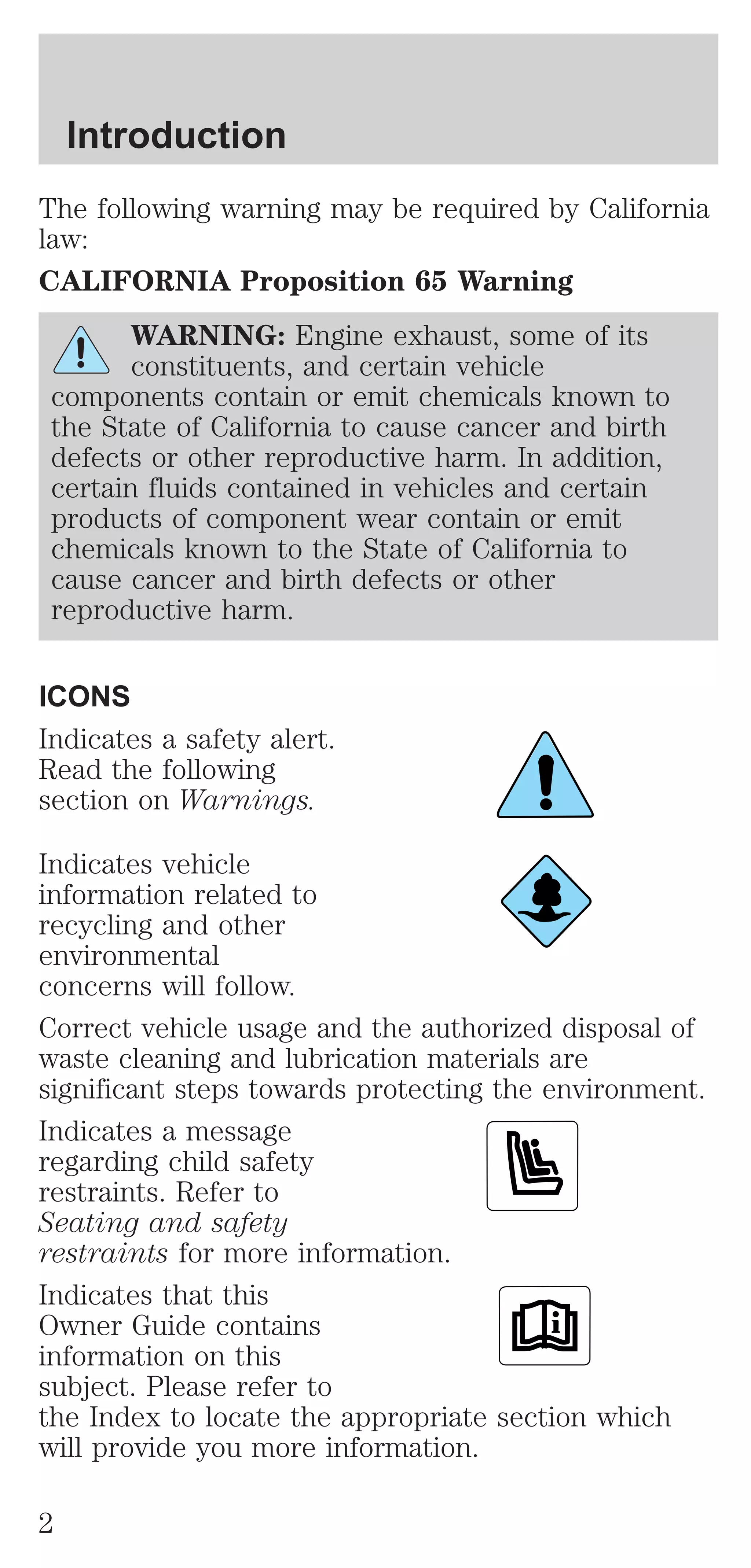
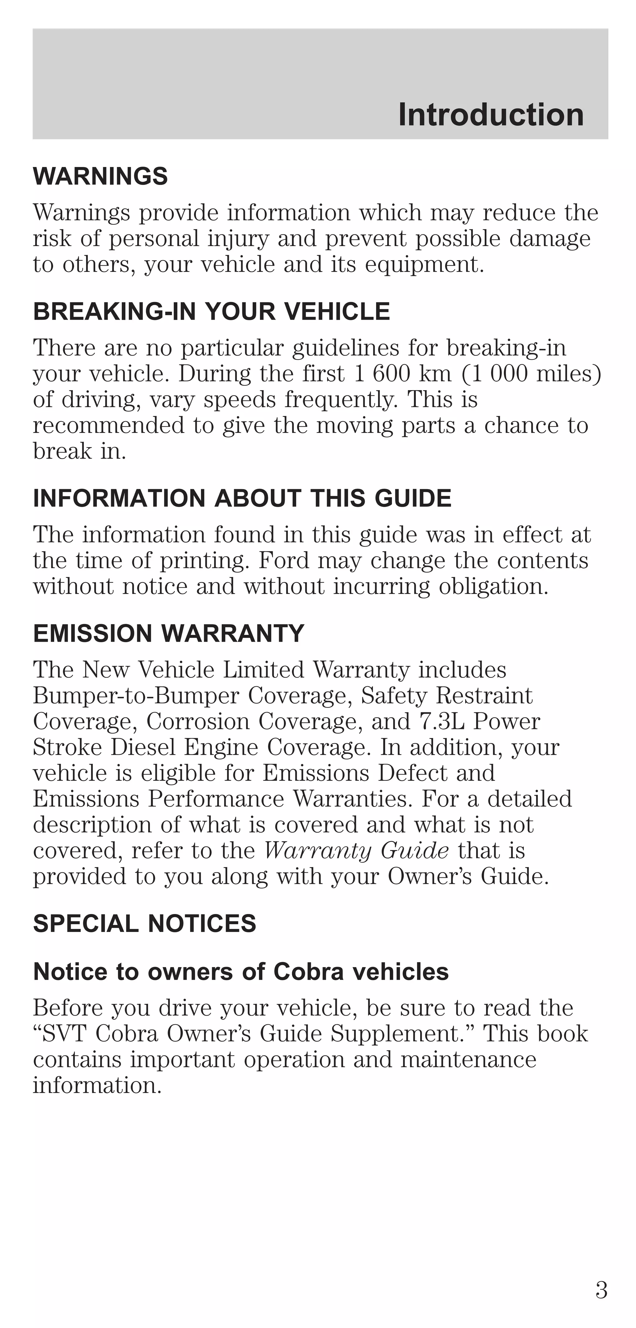
This document is an owner's manual that provides information about operating a Ford vehicle. It includes sections on instrumentation, controls, seating and safety, starting and driving, maintenance, capacities and specifications. The introduction section describes the purpose of the guide and various warning symbols found in the vehicle. It also contains a warning about chemicals that can cause cancer and birth defects.


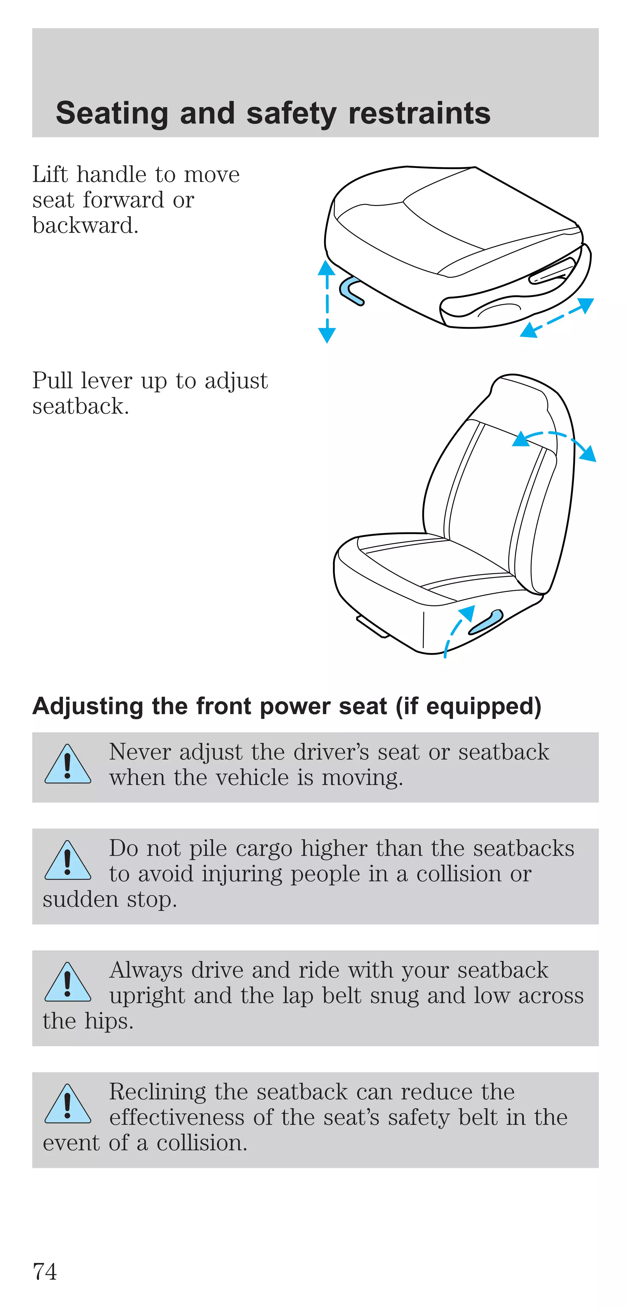

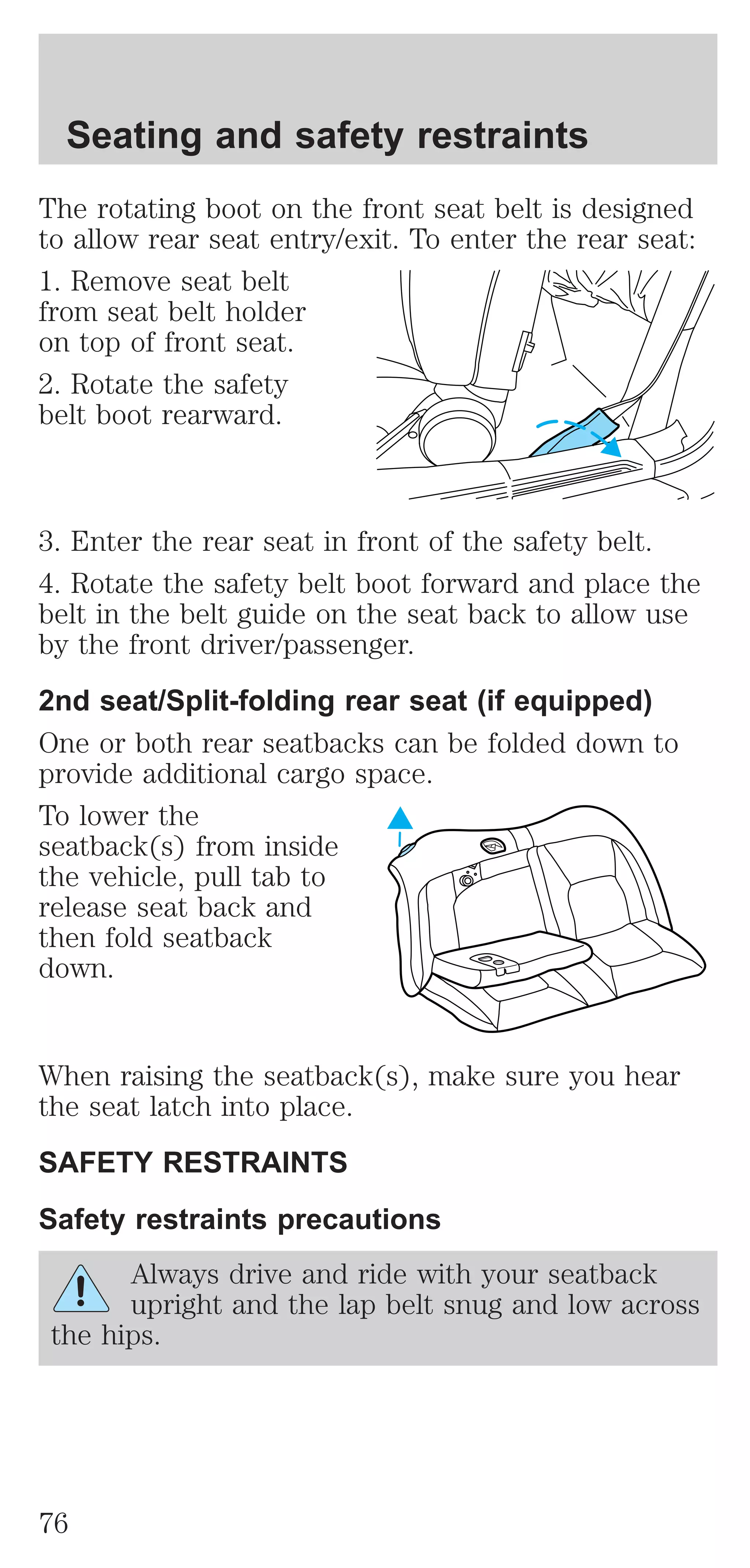

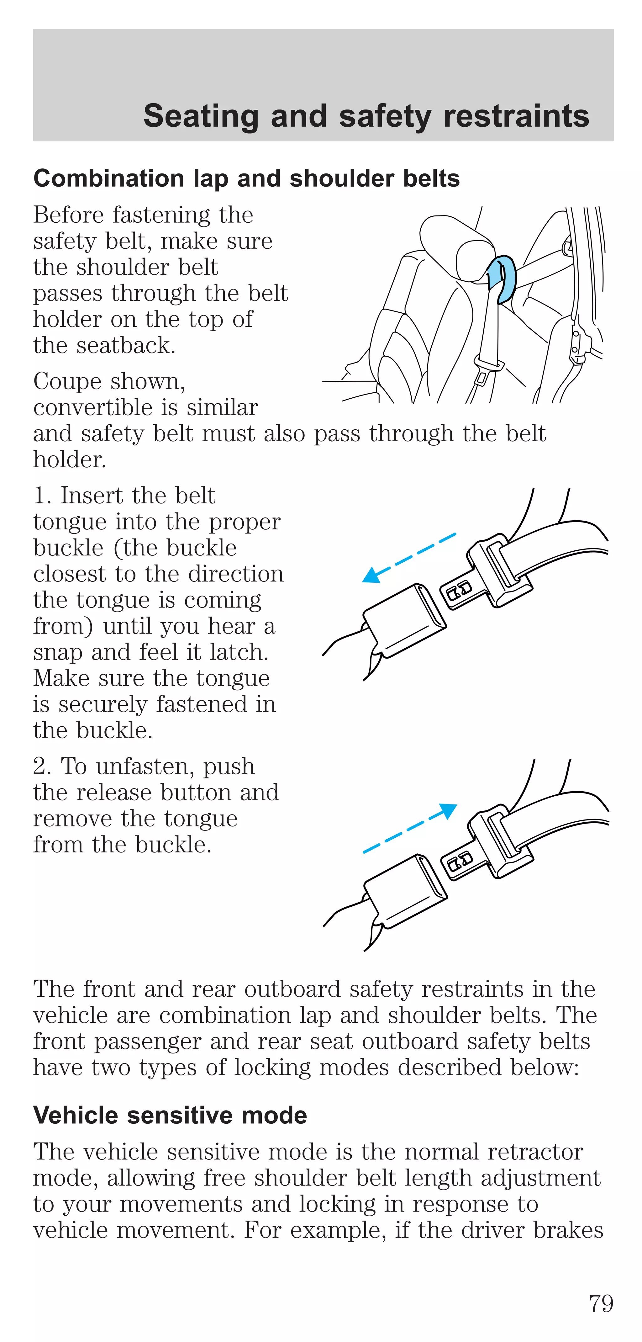


![Seating and safety restraints
A difficulty with the system is indicated by one or
more of the following:
² The readiness light
will either flash or
stay lit.
AIR
BAG
² The readiness light will not illuminate immediately
after ignition is turned on.
² A series of five beeps will be heard. The tone
pattern will repeat periodically until the problem
and/or light are repaired.
If any of these things happen, even intermittently,
have the SRS serviced at your dealership or by a
qualified technician immediately. Unless serviced,
the system may not function properly in the event of
a collision.
Disposal of air bags and air bag equipped
vehicles (including pretensioners)
For disposal of air bags or air bag equipped vehicles,
see your local dealership or qualified technician. Air
bags MUST BE disposed of by qualified personnel.
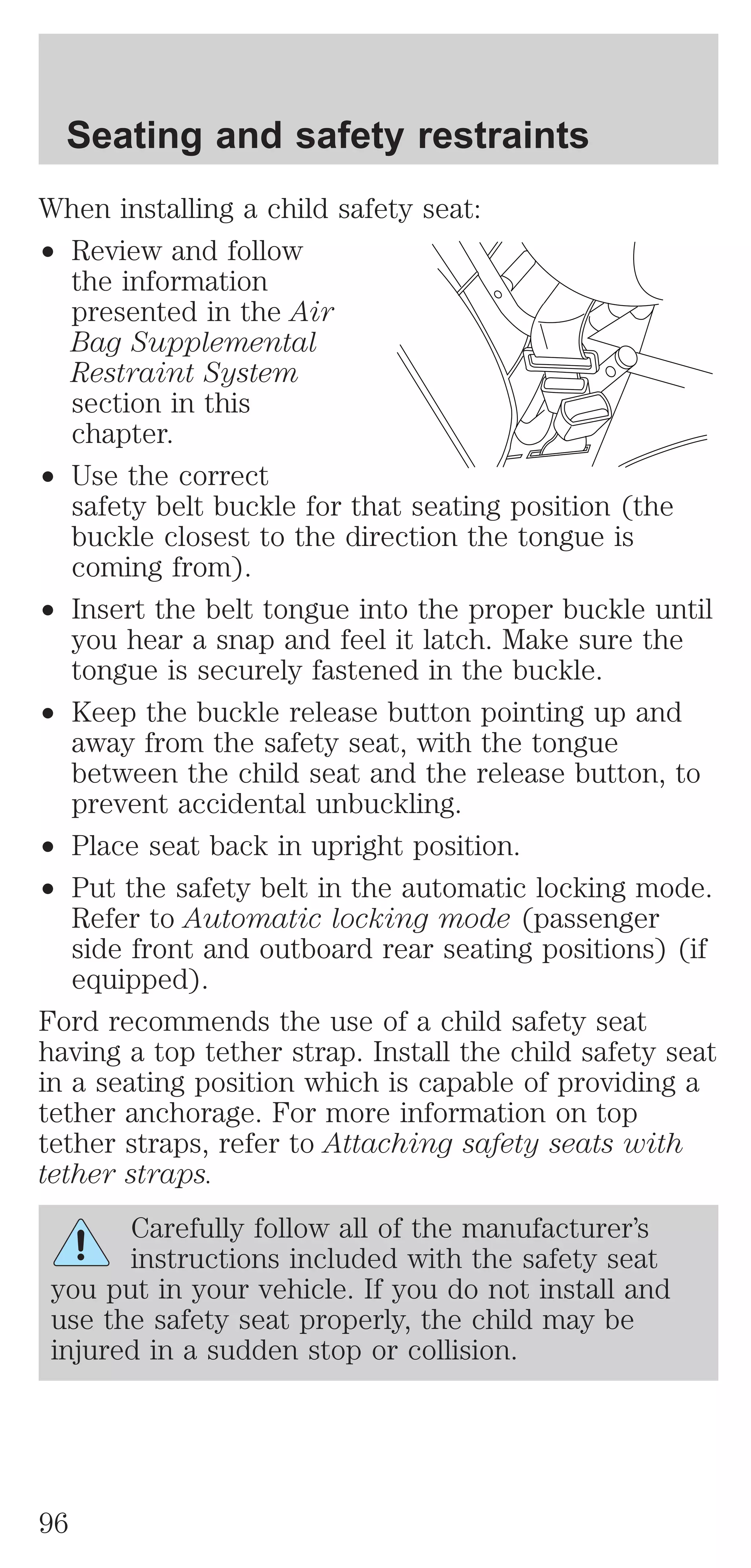
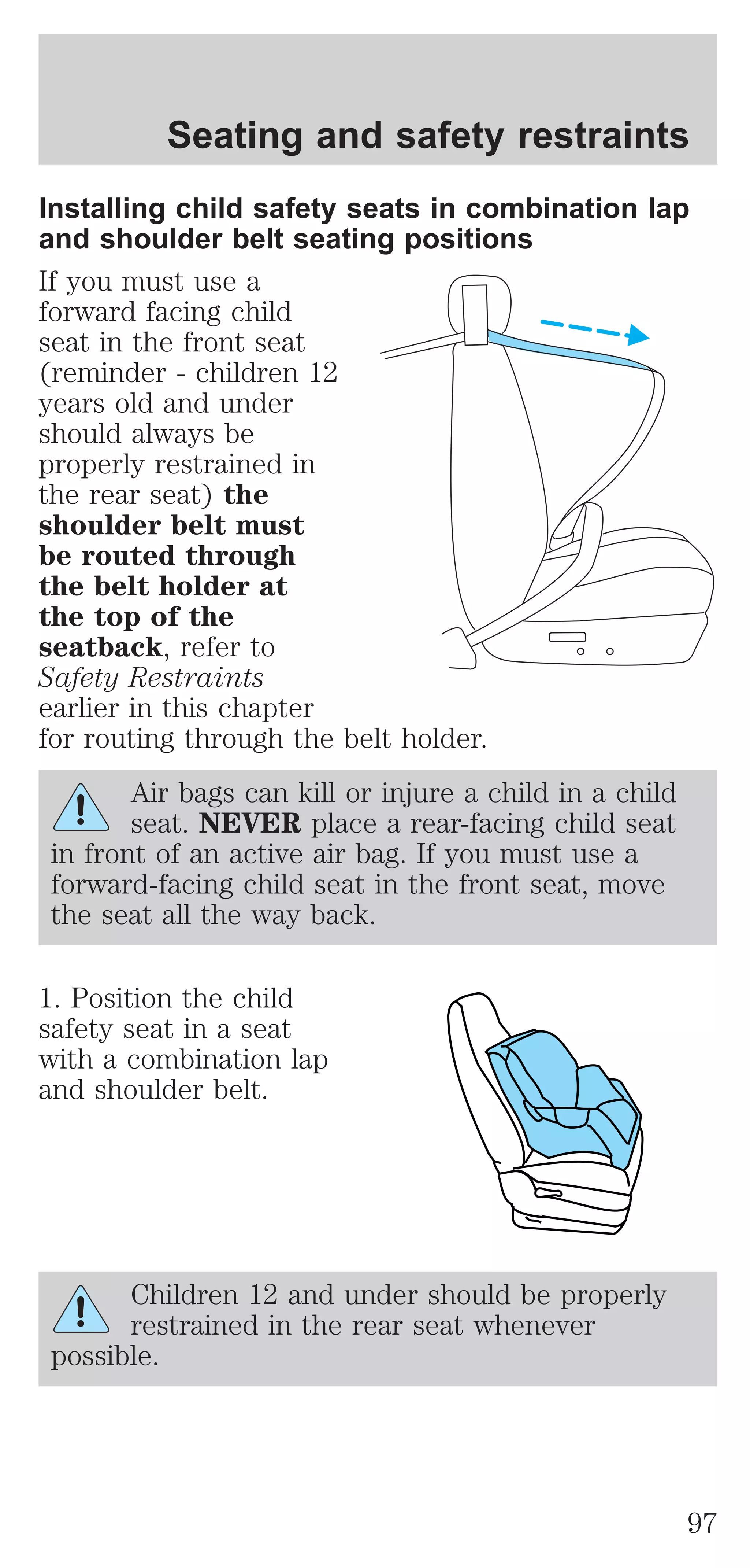
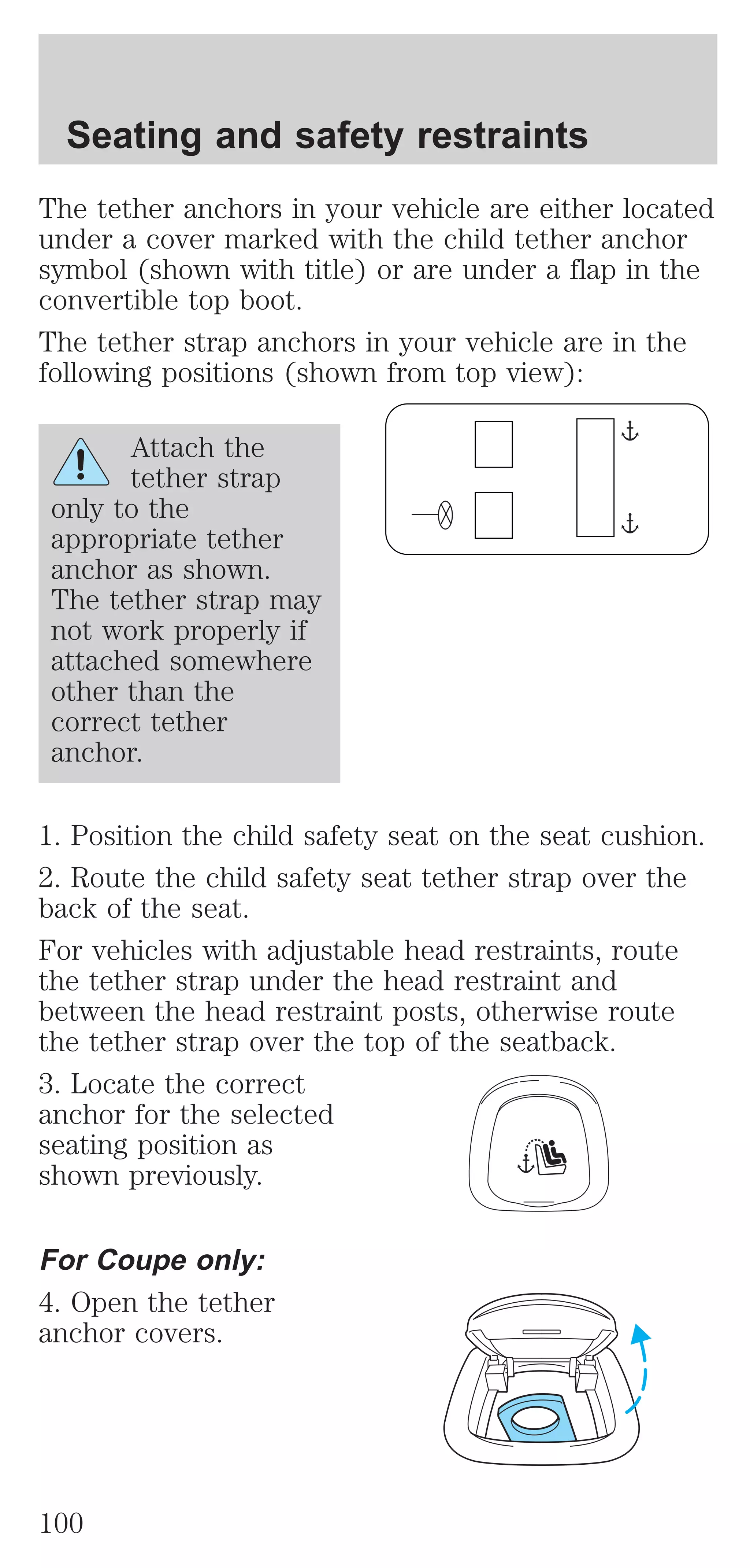
SAFETY RESTRAINTS FOR CHILDREN
See the following sections for directions on how to
properly use safety restraints for children. Also see
Air Bag Supplemental Restraint System (SRS) in
this chapter for special instructions about using air
bags.
Important child restraint precautions
You are required by law to use safety restraints for
children in the U.S. and Canada. If small children
ride in your vehicle (generally children who are four
years old or younger and who weigh 18 kg [40 lbs]
or less), you must put them in safety seats made
especially for children. Check your local and state or
provincial laws for specific requirements regarding
the safety of children in your vehicle.
93](https://image.slidesharecdn.com/01mustang-140831143518-phpapp02/75/01-mustang-93-2048.jpg)


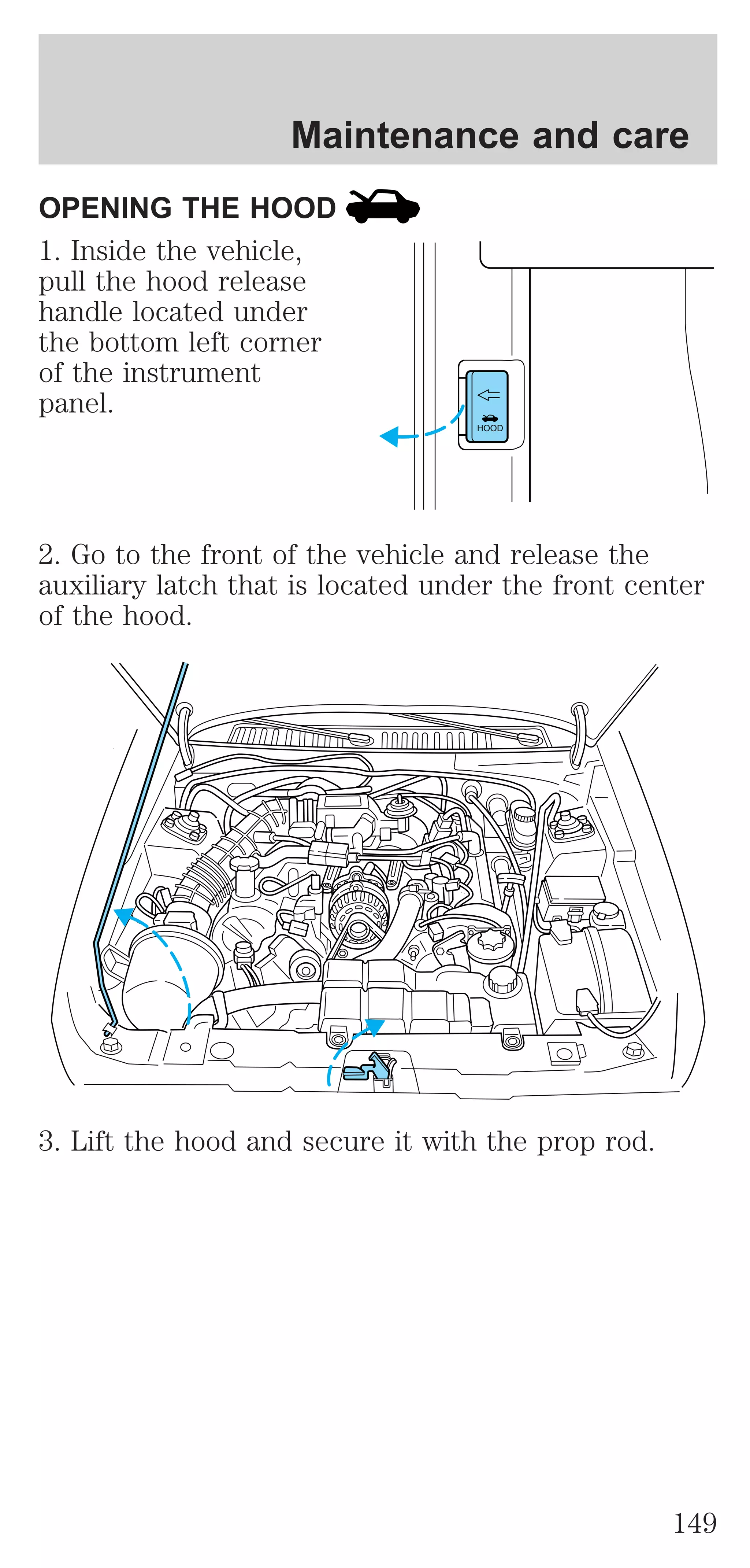
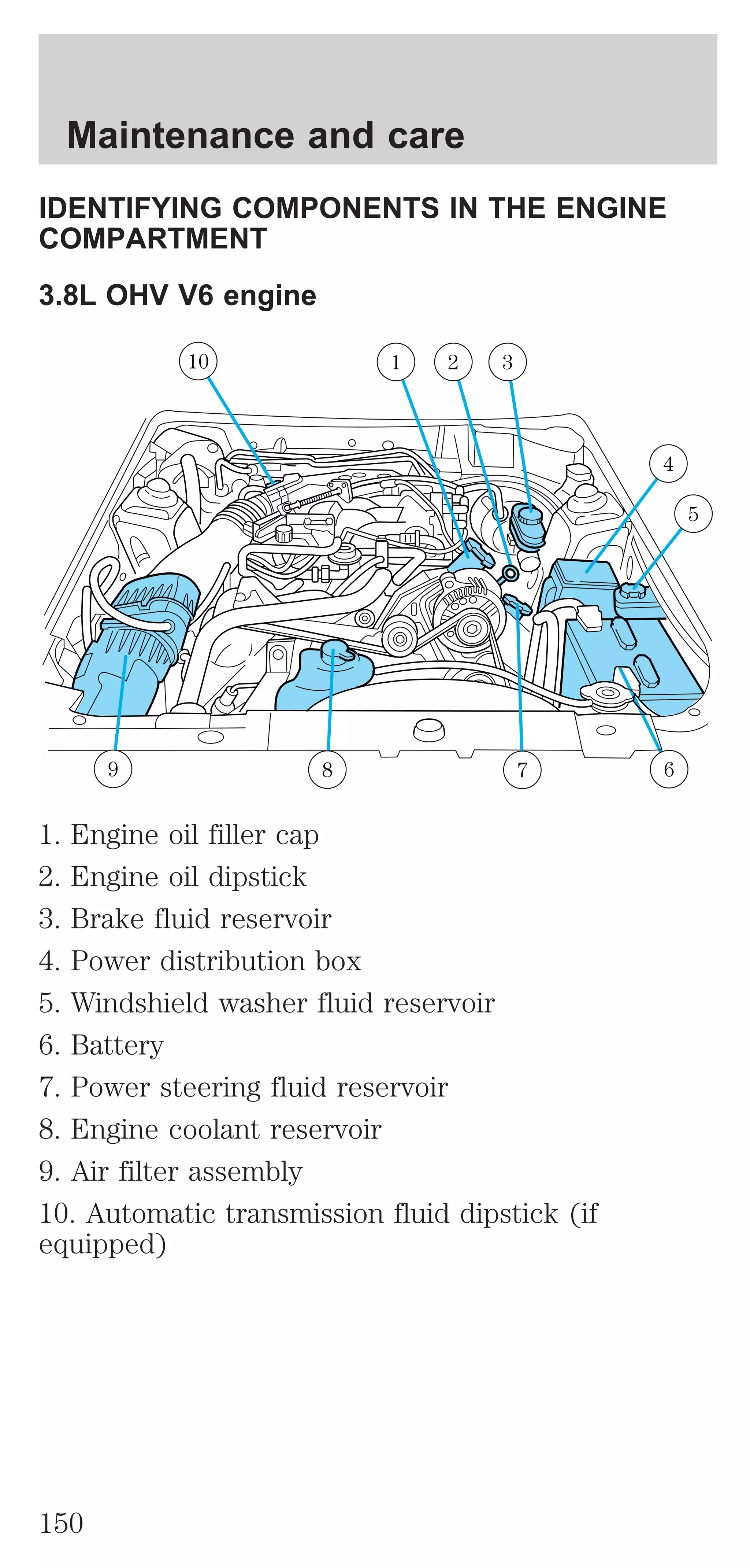
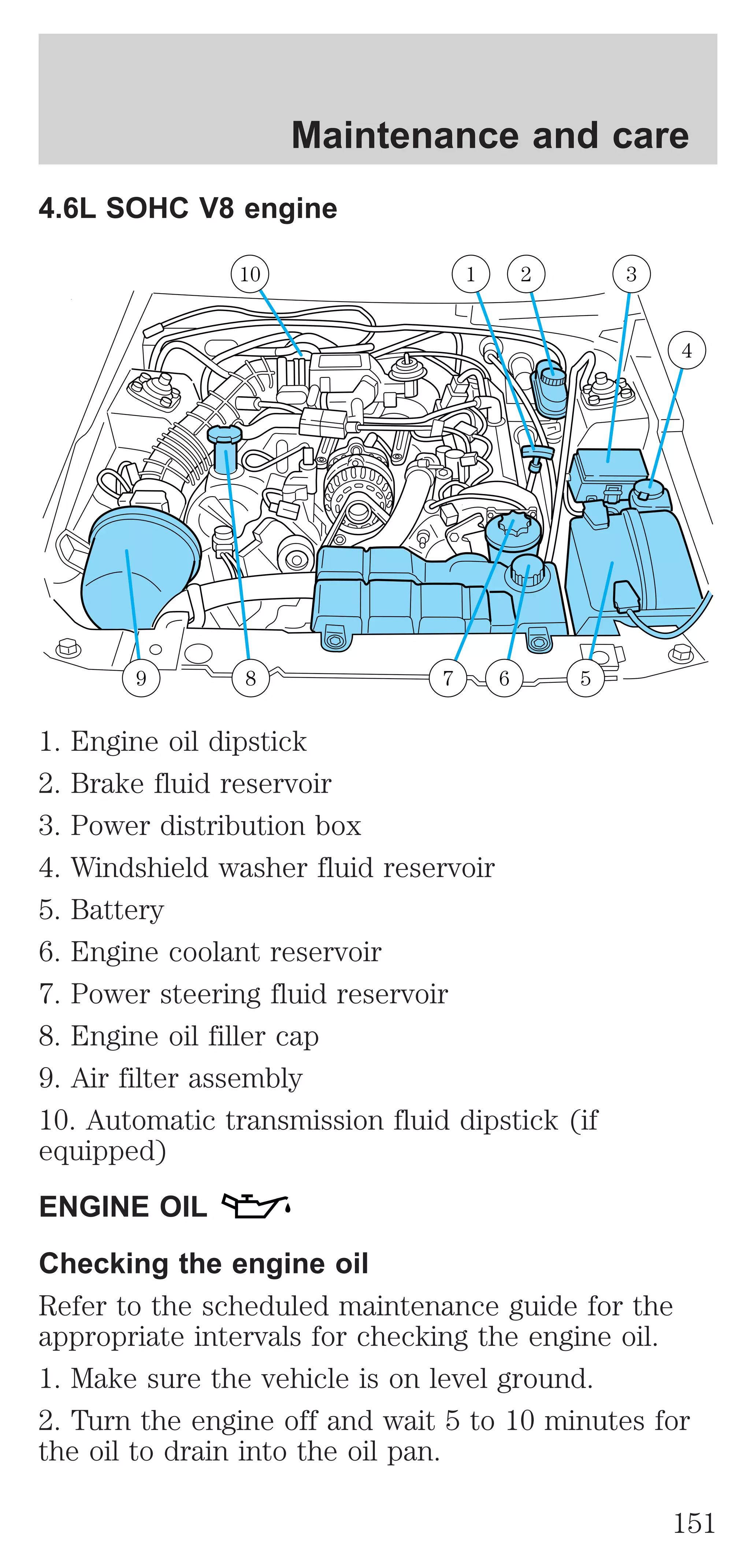
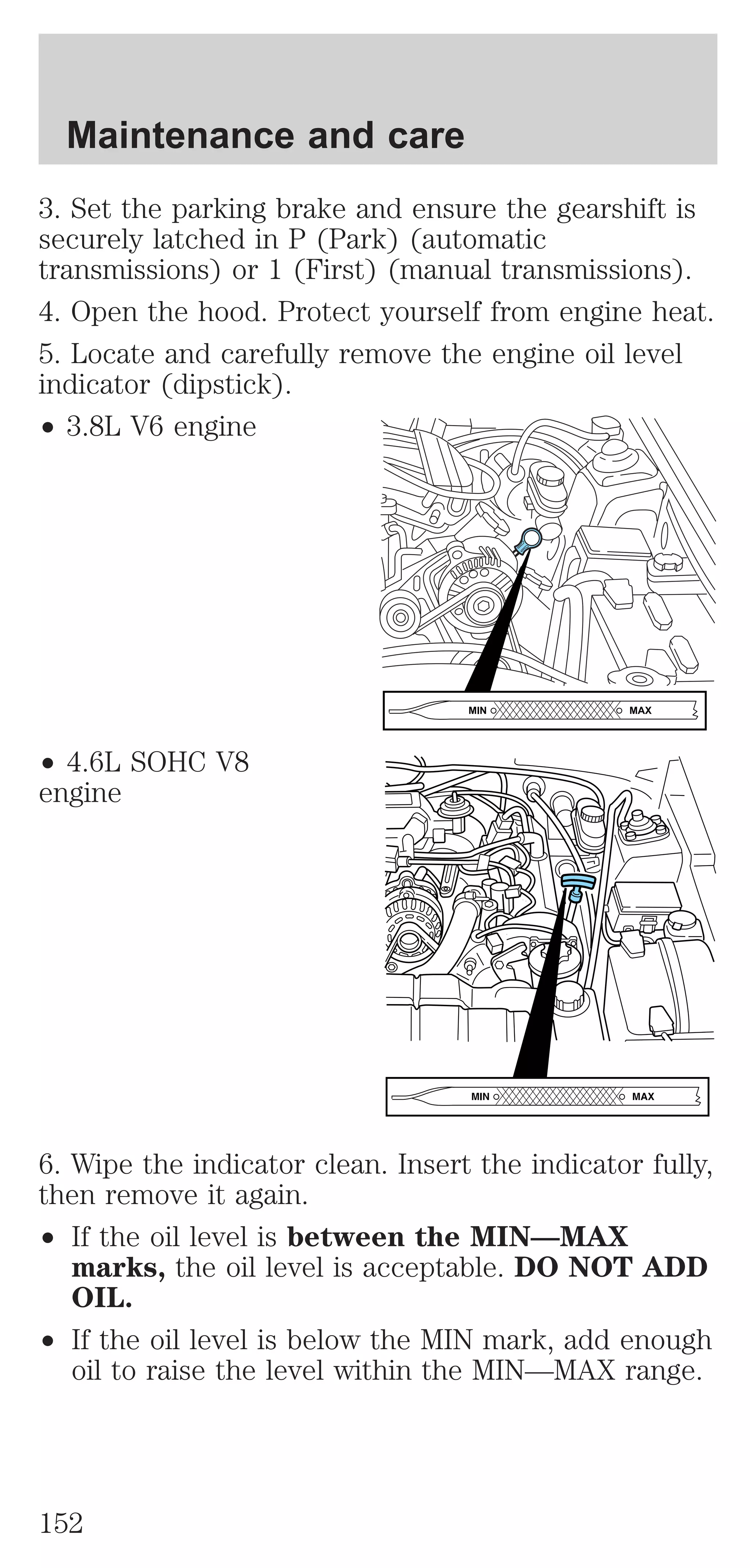
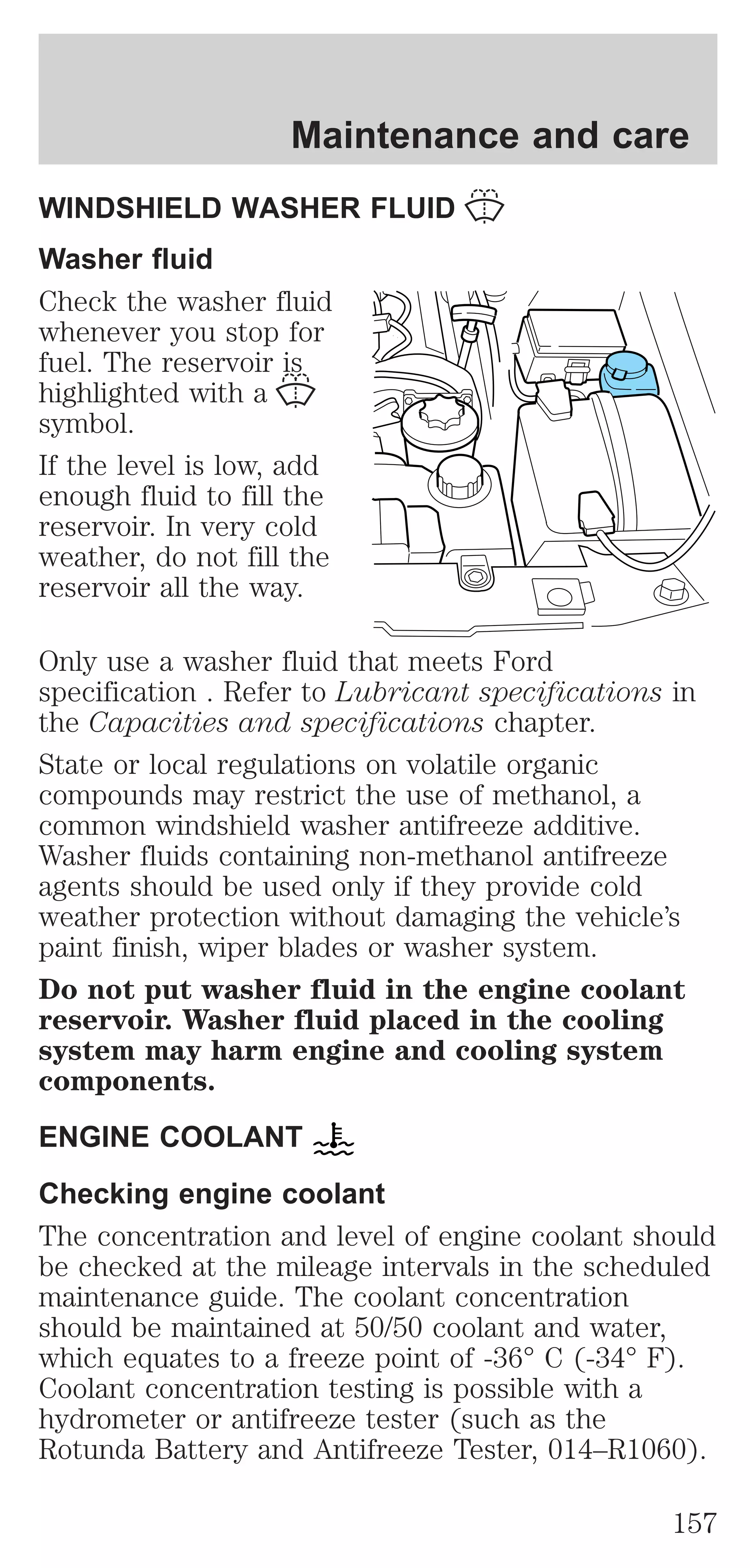

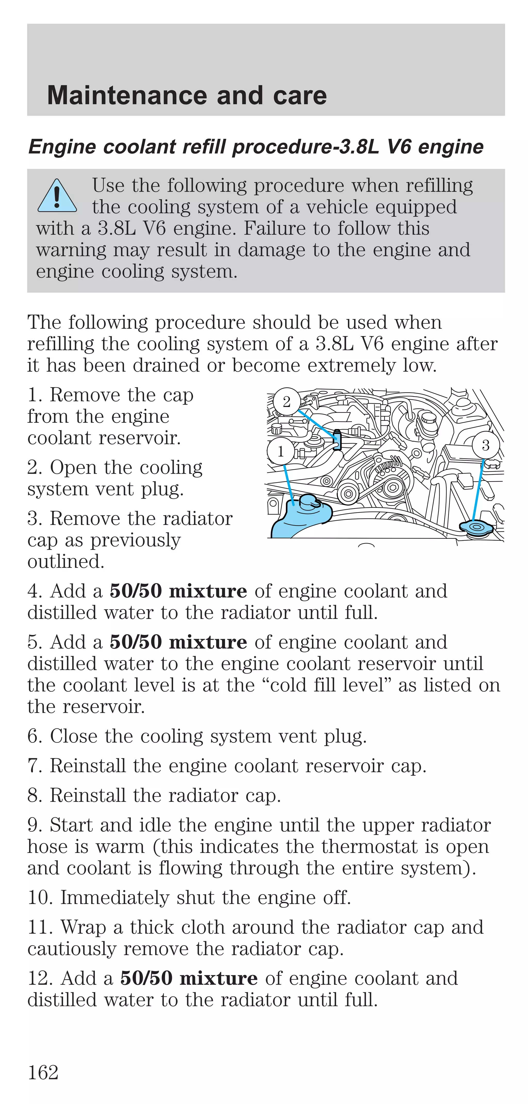
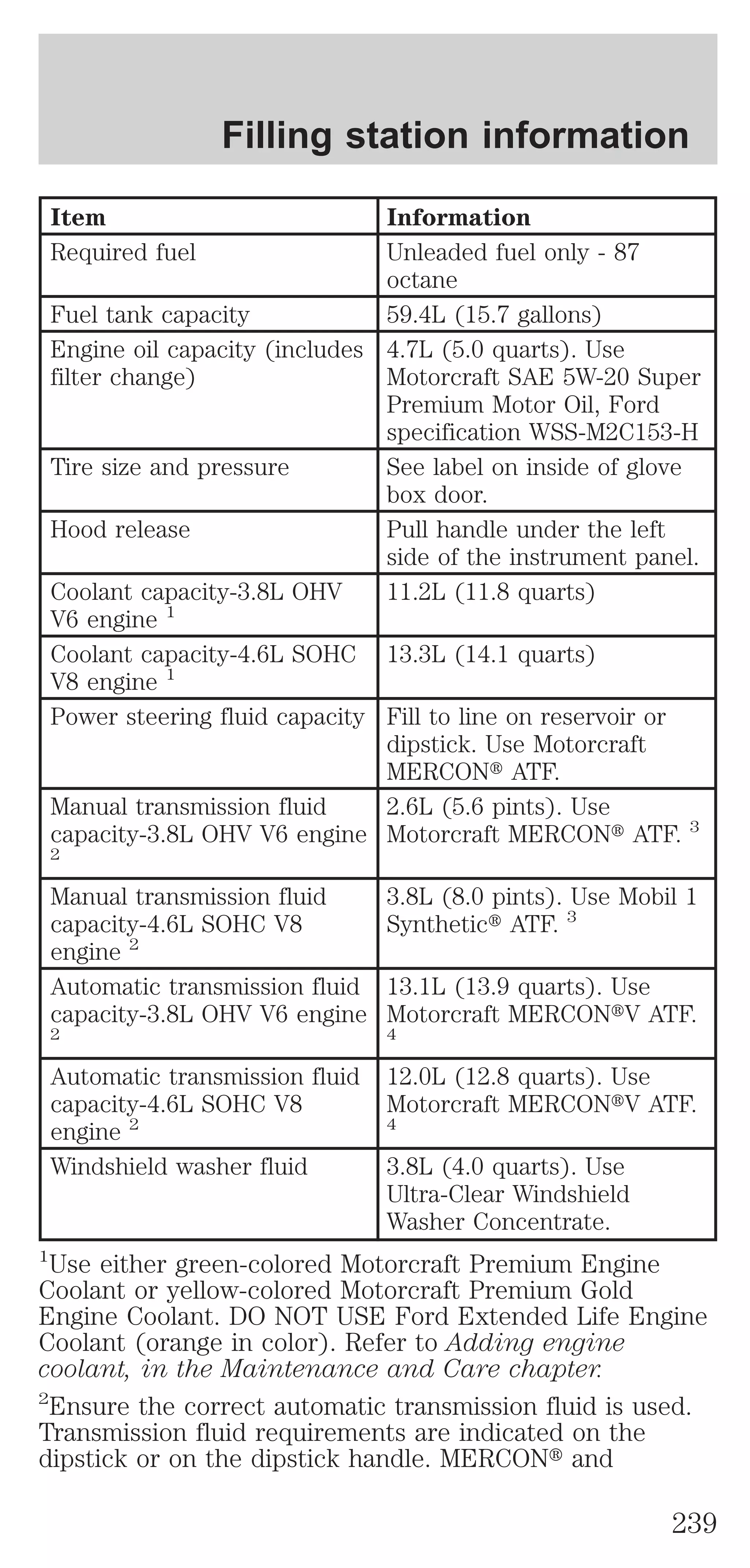
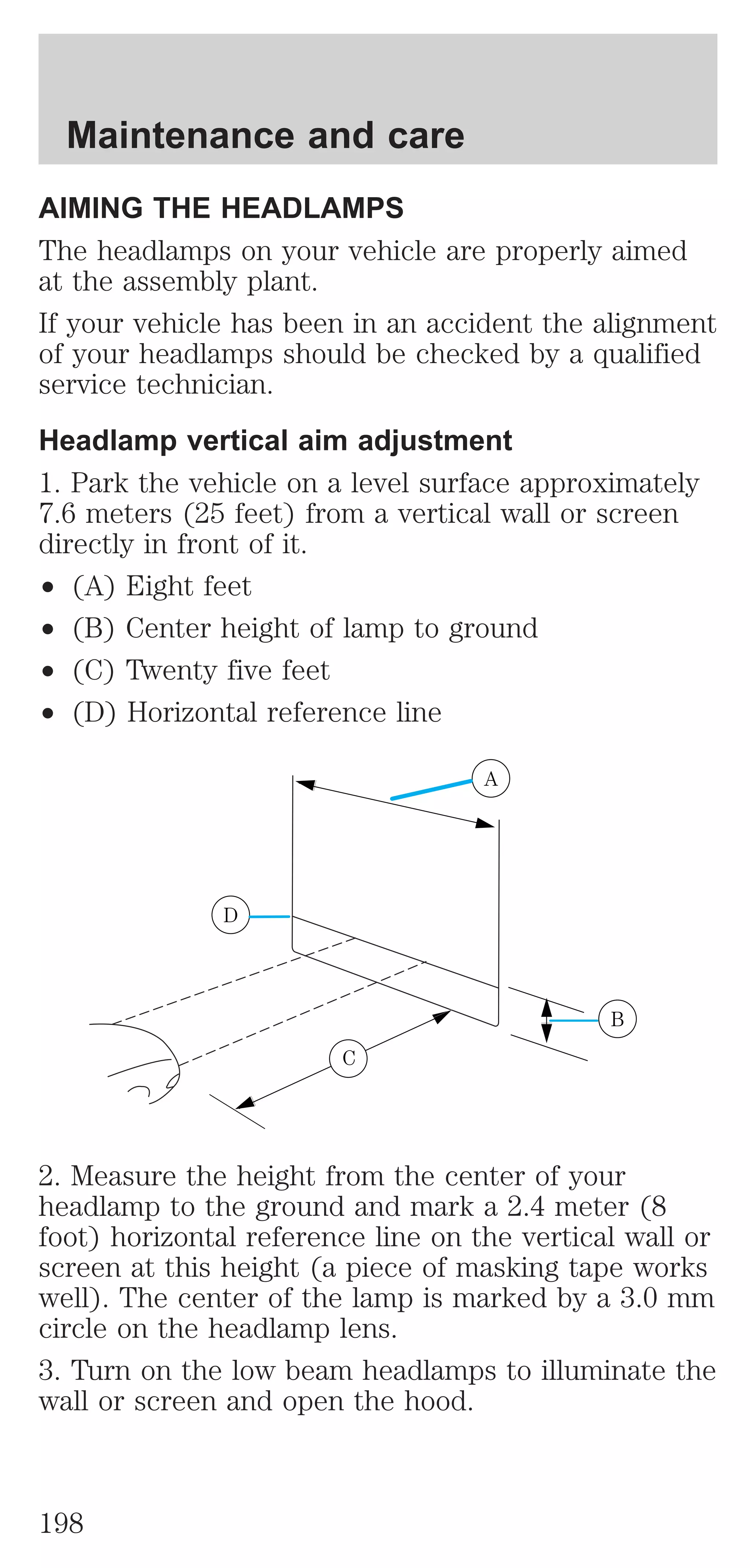
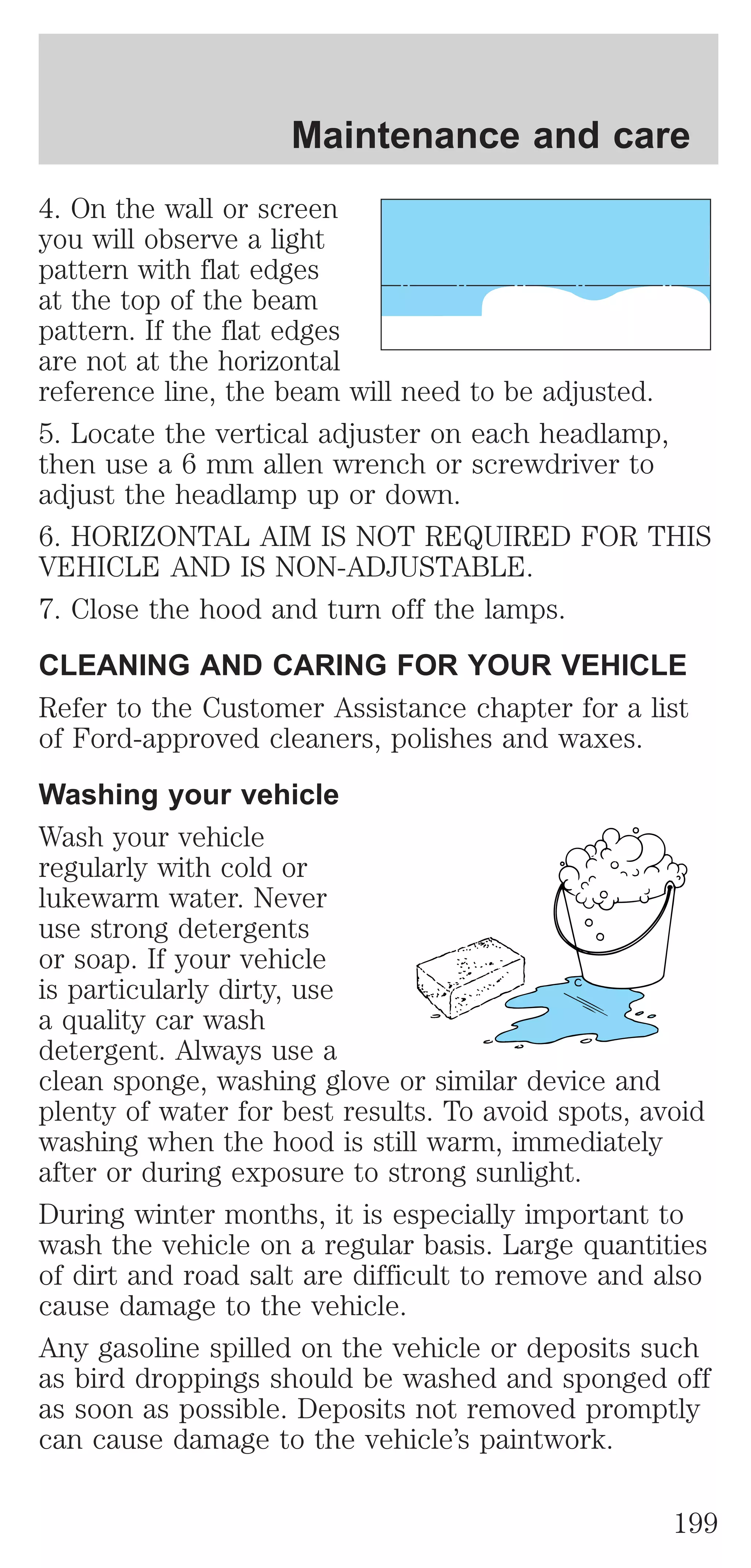
![Maintenance and care
Coolant refill capacity
To find out how much fluid your vehicle’s cooling
system can hold, refer to Refill capacities in the
Capacities and specifications chapter.
Fill your engine coolant reservoir as outlined in
Adding engine coolant in this chapter.
Severe climates
If you drive in extremely cold climates (less than
–36° C [–34° F]):
² it may be necessary to increase the coolant
concentration above 50%.
² NEVER increase the coolant concentration
above 60%.
² increased engine coolant concentrations
above 60% will decrease the overheat
protection characteristics of the engine
coolant and may cause engine damage.
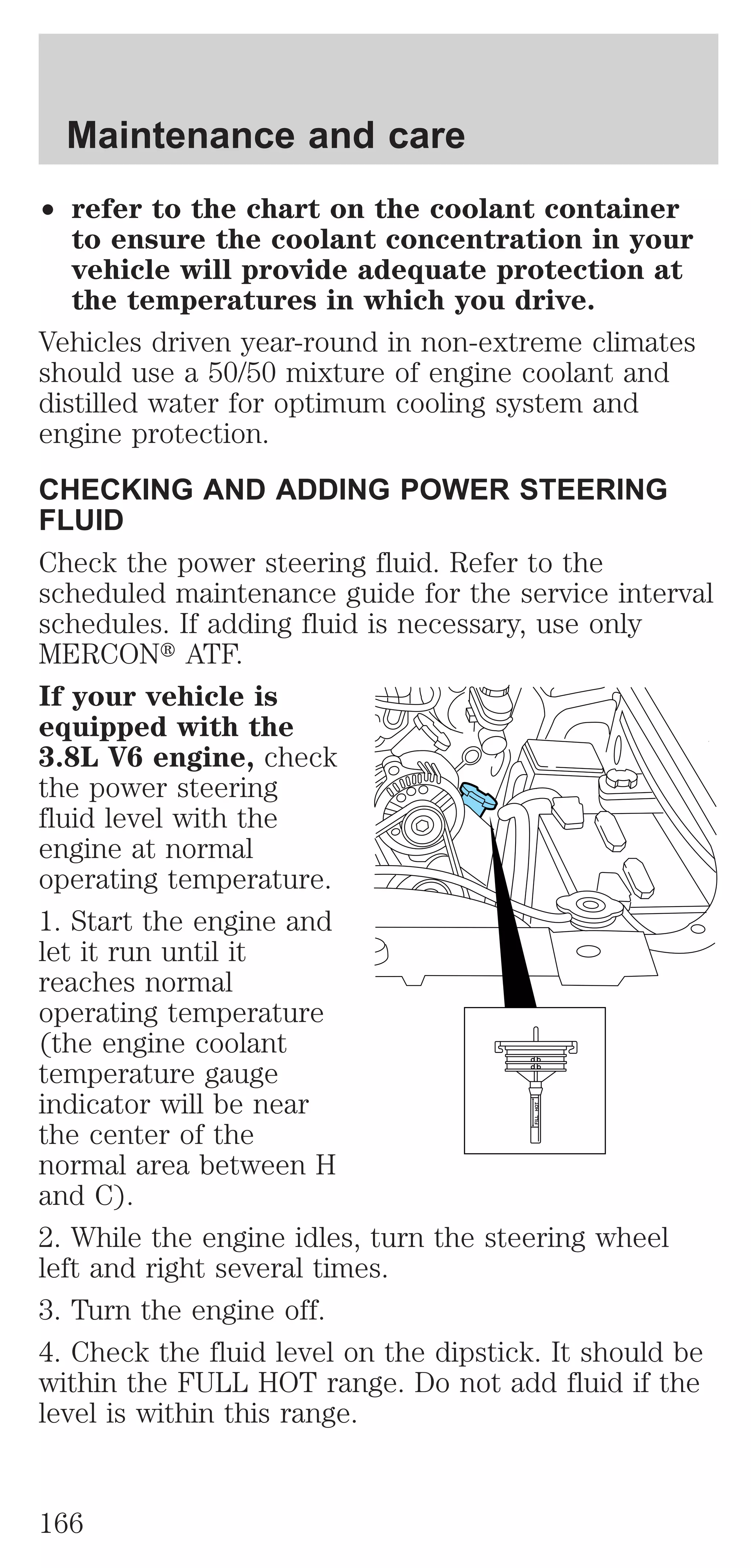
² refer to the chart on the coolant container
to ensure the coolant concentration in your
vehicle will provide adequate freeze
protection at the temperatures in which you
drive in the winter months.
If you drive in extremely hot climates:
² it is still necessary to maintain the coolant
concentration above 40%.
² NEVER decrease the coolant concentration
below 40%.
² decreased engine coolant concentrations
below 40% will decrease the corrosion
protection characteristics of the engine
coolant and may cause engine damage.
² decreased engine coolant concentrations
below 40% will decrease the freeze
protection characteristics of the engine
coolant and may cause engine damage.
165](https://image.slidesharecdn.com/01mustang-140831143518-phpapp02/75/01-mustang-165-2048.jpg)
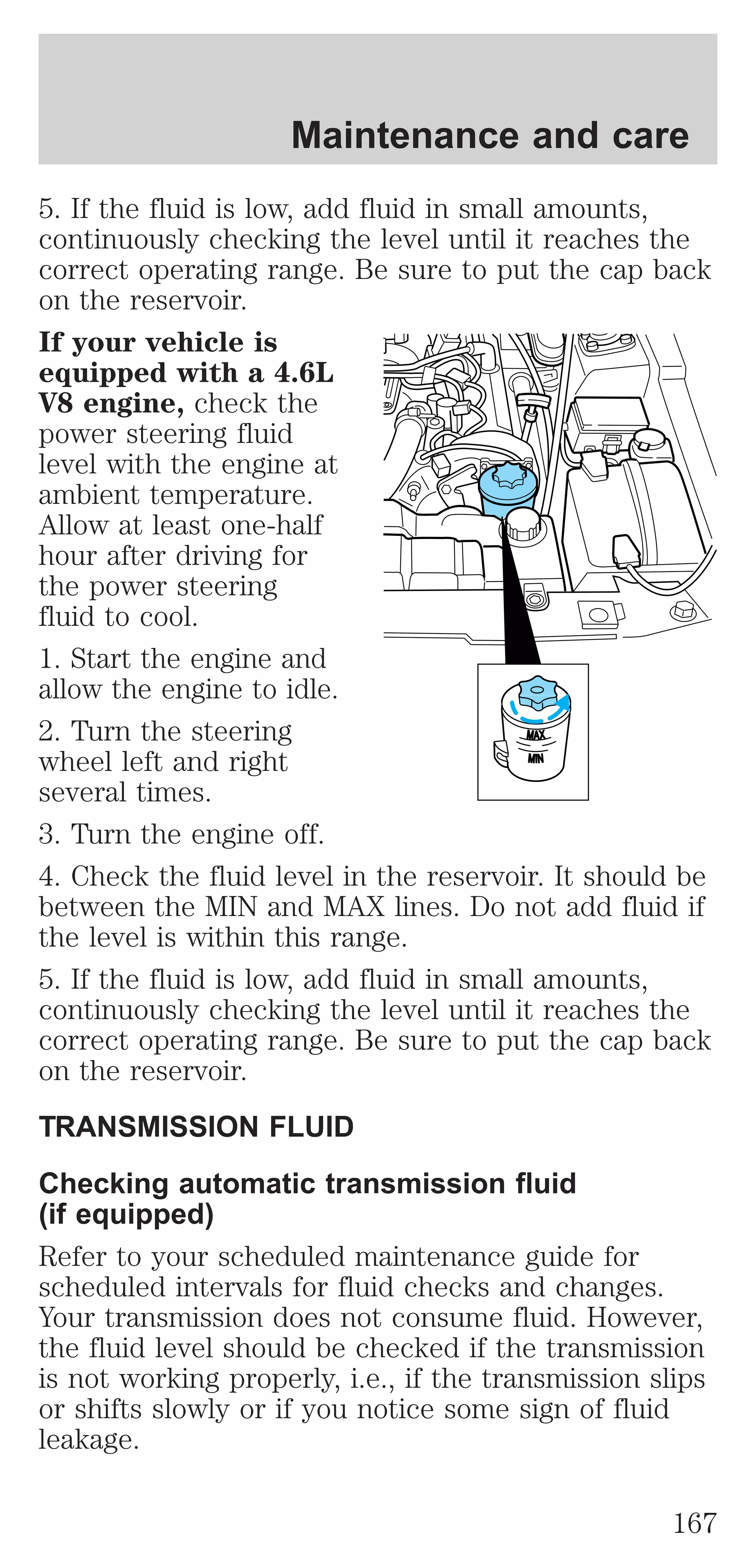
![Maintenance and care
Automatic transmission fluid expands when warmed.
To obtain an accurate fluid check, drive the vehicle
until it is at normal operating temperature
(approximately 30 km [20 miles]). If your vehicle has
been operated for an extended period at high
speeds, in city traffic during hot weather or pulling a
trailer, the vehicle should be turned off for about 30
minutes to allow fluid to cool before checking.
1. Drive the vehicle 30 km (20 miles) or until it
reaches normal operating temperature.
2. Park the vehicle on a level surface and engage the
parking brake.
3. With the parking brake engaged and your foot on
the brake pedal, start the engine and move the
gearshift lever through all of the gear ranges. Allow
sufficient time for each gear to engage.
4. Latch the gearshift lever in P (Park) and leave the
engine running.
5. Remove the dipstick, wiping it clean with a clean,
dry lint free rag. If necessary, refer to Identifying
components in the engine compartment in this
chapter for the location of the dipstick.
6. Install the dipstick making sure it is fully seated in
the filler tube.
7. Remove the dipstick and inspect the fluid level.
The fluid should be in the designated area for
normal operating temperature or ambient
temperature.
Low fluid level
Do not drive the
vehicle if the fluid level
is at the bottom of the
dipstick and the ambient temperature is above 10°C
(50°F).
Correct fluid level
The transmission fluid should be checked at normal
operating temperature 66°C-77°C (150°F-170°F) on
168](https://image.slidesharecdn.com/01mustang-140831143518-phpapp02/75/01-mustang-168-2048.jpg)
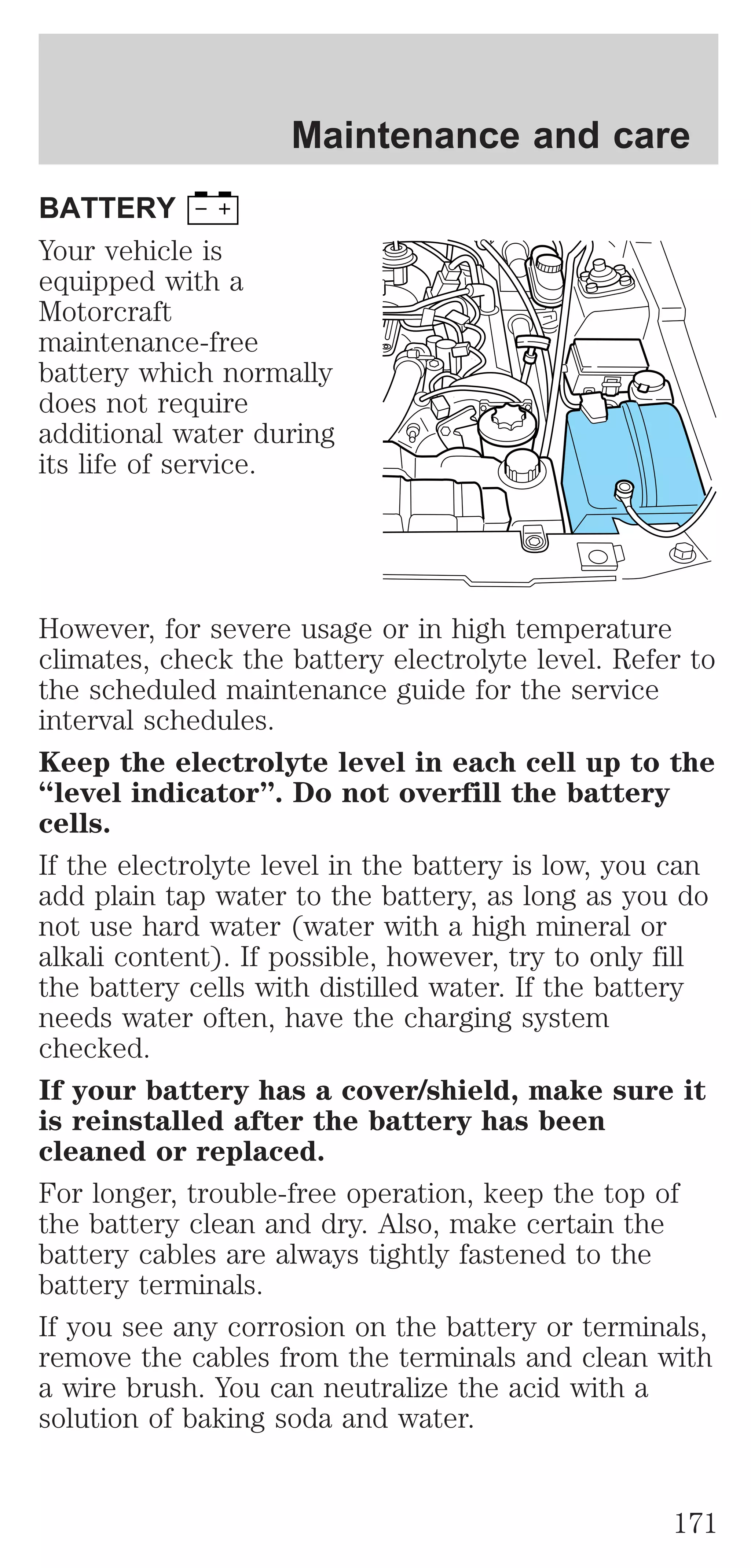
![Maintenance and care
a level surface. The normal operating temperature
can be reached after approximately 30 km (20
miles) of driving.
You can check the fluid without driving if the
ambient temperature is above 10°C (50°F). However,
if fluid is added at this time, an overfill condition
could result when the vehicle reaches normal
operating temperature.
The transmission fluid
should be in this range
if at normal operating
temperature (66°C-77°C [150°F-170°F]).
The transmission fluid
should be in this range
if at ambient
temperature (10°C-35°C [50°F-95°F]).
High fluid level
Fluid levels above the
safe range may result
in transmission failure.
An overfill condition of transmission fluid may cause
shift and/or engagement concerns and/or possible
damage.
High fluid levels can be caused by an overheating
condition.
Adjusting automatic transmission fluid levels
Before adding any fluid, make sure the correct type
is used. The type of fluid used is normally indicated
on the dipstick and also in the Lubricant
specifications section in the Capacities and
specifications chapter.
Use of a non-approved automatic transmission
fluid may cause internal transmission
component damage.
If necessary, add fluid in 250 ml (1/2 pint)
increments through the filler tube until the level is
correct.
169](https://image.slidesharecdn.com/01mustang-140831143518-phpapp02/75/01-mustang-169-2048.jpg)


![Maintenance and care
Keep a record for at least one month and record the
type of driving (city or highway). This will provide
an accurate estimate of the vehicle’s fuel economy
under current driving conditions. Additionally,
keeping records during summer and winter will show
how temperature impacts fuel economy. In general,
lower temperatures give lower fuel economy.
Driving style — good driving and fuel economy
habits
Give consideration to the lists that follow and you
may be able to change a number of variables and
improve your fuel economy.
Habits
² Smooth, moderate operation can yield up to 10%
savings in fuel.
² Steady speeds without stopping will usually give
the best fuel economy.
² Idling for long periods of time (greater than one
minute) may waste fuel.
² Anticipate stopping; slowing down may eliminate
the need to stop.
² Sudden or hard accelerations may reduce fuel
economy.
² Slow down gradually.
² Driving at reasonable speeds (traveling at 88 km/h
[55 mph] uses 15% less fuel than traveling at 105
km/h [65 mph]).
² Revving the engine before turning it off may
reduce fuel economy.
² Using the air conditioner or defroster may reduce
fuel economy.
² You may want to turn off the speed control in
hilly terrain if unnecessary shifting between third
and fourth gear occurs. Unnecessary shifting of
this type could result in reduced fuel economy.
188](https://image.slidesharecdn.com/01mustang-140831143518-phpapp02/75/01-mustang-188-2048.jpg)
![Maintenance and care
² Warming up a vehicle on cold mornings is not
required and may reduce fuel economy.
² Resting your foot on the brake pedal while driving
may reduce fuel economy.
² Combine errands and minimize stop-and-go
driving.
Maintenance
² Keep tires properly inflated and use only
recommended size.
² Operating a vehicle with the wheels out of
alignment will reduce fuel economy.
² Use recommended engine oil. Refer to Lubricant
specifications.
² Perform all regularly scheduled maintenance
items. Follow the recommended maintenance
schedule and owner maintenance checks found in
your vehicle scheduled maintenance guide.
Conditions
² Heavily loading a vehicle or towing a trailer may
reduce fuel economy at any speed.
² Carrying unnecessary weight may reduce fuel
economy (approximately 0.4 km/L [1 mpg] is lost
for every 180 kg [400 lb] of weight carried).
² Adding certain accessories to your vehicle (for
example bug deflectors, rollbars/light bars,
running boards, ski/luggage racks) may reduce
fuel economy.
² Using fuel blended with alcohol may lower fuel
economy.
² Fuel economy may decrease with lower
temperatures during the first 12–16 km (8–10
miles) of driving.
² Driving on flat terrain offers improved fuel
economy as compared to driving on hilly terrain.
² Transmissions give their best fuel economy when
operated in the top cruise gear and with steady
pressure on the gas pedal.
² Close windows for high speed driving.
189](https://image.slidesharecdn.com/01mustang-140831143518-phpapp02/75/01-mustang-189-2048.jpg)


![Customer assistance
Front end covers (full and mini)
Lubricants and oils
Molded splash guards
Seat belt extenders
Tonneau covers (mini)
Touch-up paint
Universal floor mats
For maximum vehicle performance, keep the
following information in mind when adding
accessories or equipment to your vehicle:
² When adding accessories, equipment, passengers
and luggage to your vehicle, do not exceed the
total weight capacity of the vehicle or of the front
or rear axle (GVWR or GAWR as indicated on the
Safety compliance certification label). Consult
your dealer for specific weight information.
² The Federal Communications Commission (FCC)
and Canadian Radio Telecommunications
Commission (CRTC) regulate the use of mobile
communications systems - such as two-way
radios, telephones and theft alarms - that are
equipped with radio transmitters. Any such
equipment installed in your vehicle should comply
with FCC or CRTC regulations and should be
installed only by a qualified service technician.
² Mobile communications systems may harm the
operation of your vehicle, particularly if they are
not properly designed for automotive use or are
not properly installed. When operated, such
systems may cause the engine to stumble or stall
or cause the transmission to be damaged or
operate improperly. In addition, such systems may
be damaged or their performance may be affected
by operating your vehicle. (Citizens band [CB]
transceivers, garage door openers and other
transmitters with outputs of five watts or less will
not ordinarily affect your vehicle’s operation.)
224](https://image.slidesharecdn.com/01mustang-140831143518-phpapp02/75/01-mustang-224-2048.jpg)