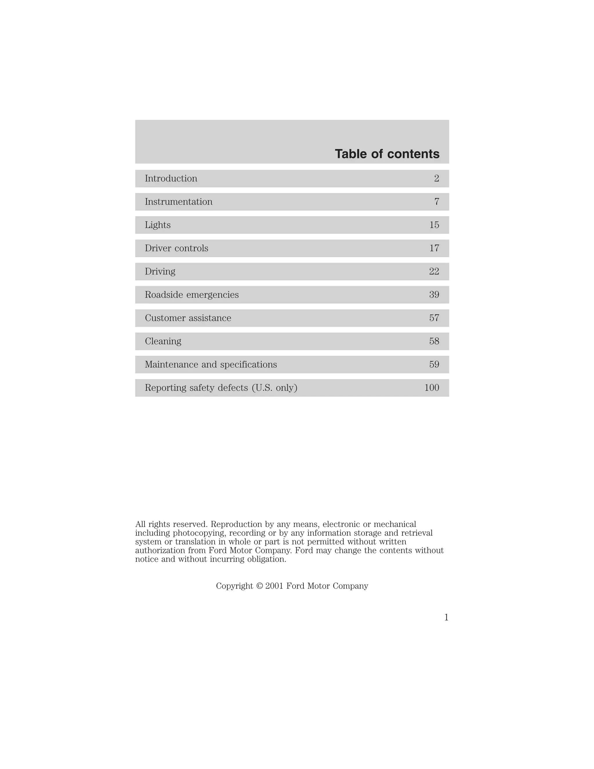
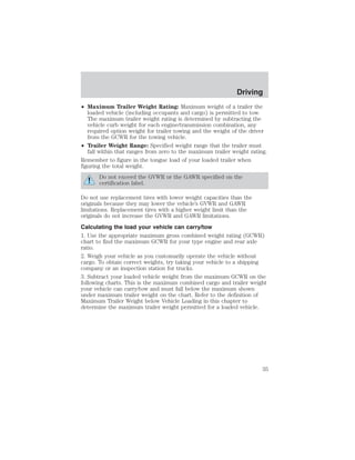
The document provides an overview of various vehicle controls and systems, including:
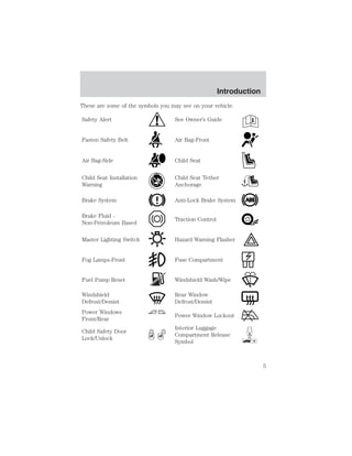
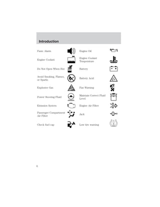
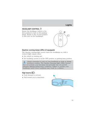
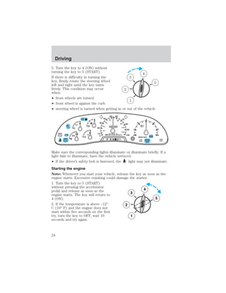
- Headlamp controls for parking lamps, headlamps, and daytime running lamps
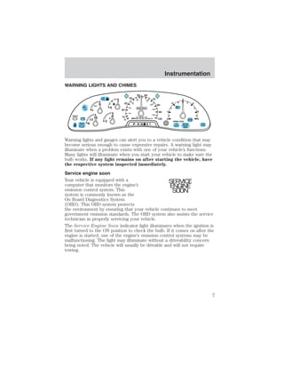
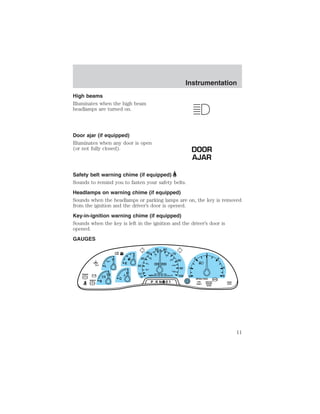
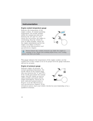
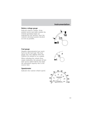
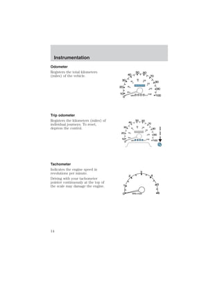
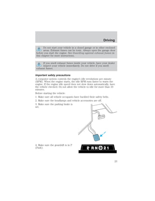
- Instrumentation gauges like temperature, oil pressure, fuel level, and warning lights
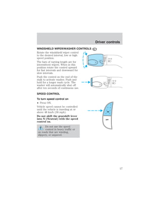
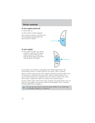
- Windshield wiper/washer controls and speed control functions
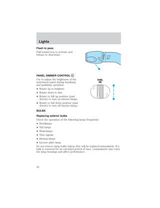
- Exterior light bulbs that should be checked regularly
The summary highlights the main topics covered in the owner's manual sections around lights, gauges, wiper/washer functions, and basic vehicle controls.
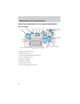
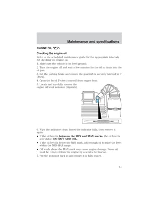
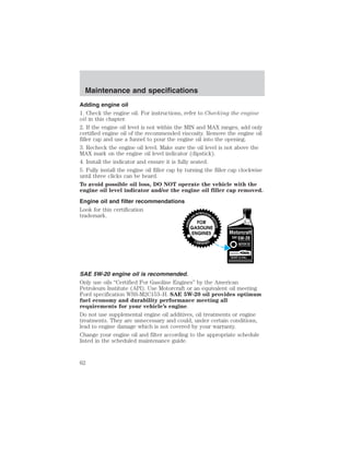
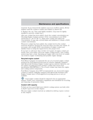
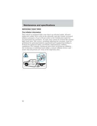
![Maintenance and specifications
Severe climates
If you drive in extremely cold climates (less than –36° C [–34° F]):
• It may be necessary to increase the coolant concentration
above 50%.
• NEVER increase the coolant concentration above 60%.
• Increased engine coolant concentrations above 60% will
decrease the overheat protection characteristics of the engine
coolant and may cause engine damage.
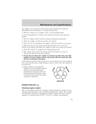
• Refer to the chart on the coolant container to ensure the
coolant concentration in your vehicle will provide adequate
freeze protection at the temperatures in which you drive in the
winter months.
If you drive in extremely hot climates:
• It is still necessary to maintain the coolant concentration
above 40%.
• NEVER decrease the coolant concentration below 40%.
• Decreased engine coolant concentrations below 40% will
decrease the corrosion protection characteristics of the engine
coolant and may cause engine damage.
• Decreased engine coolant concentrations below 40% will
decrease the freeze protection characteristics of the engine
coolant and may cause engine damage.
• Refer to the chart on the coolant container to ensure the
coolant concentration in your vehicle will provide adequate
protection at the temperatures in which you drive.
Vehicles driven year-round in non-extreme climates should use a 50/50
mixture of engine coolant and distilled water for optimum cooling system
and engine protection.
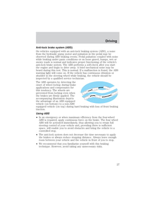
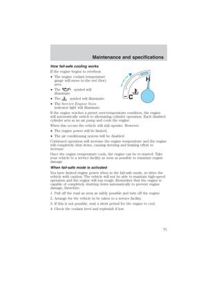
What you should know about fail-safe cooling
If the engine coolant supply is depleted, this feature allows the vehicle to
be driven temporarily before incremental component damage is incurred.
The “fail-safe” distance depends on ambient temperatures, vehicle load
and terrain.
70](https://image.slidesharecdn.com/02f-53motorhome-140829050917-phpapp01/85/02-f-53-motorhome-70-320.jpg)
![Maintenance and specifications
5. Follow one of the simple calculations in order to determine fuel
economy:
Multiply liters used by 100, then divide by total kilometers
traveled.
Divide total miles traveled by total gallons used.
Keep a record for at least one month and record the type of driving (city
or highway). This will provide an accurate estimate of the vehicle’s fuel
economy under current driving conditions. Additionally, keeping records
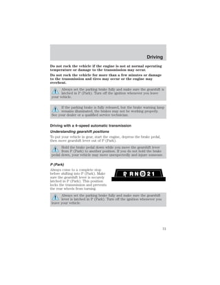
during summer and winter will show how temperature impacts fuel
economy. In general, lower temperatures give lower fuel economy.
Driving style — good driving and fuel economy habits
Give consideration to the lists that follow and you may be able to change
a number of variables and improve your fuel economy.
Habits
• Smooth, moderate operation can yield up to 10% savings in fuel.
• Steady speeds without stopping will usually give the best fuel
economy.
• Idling for long periods of time (greater than one minute) may waste
fuel.
• Anticipate stopping; slowing down may eliminate the need to stop.
• Sudden or hard accelerations may reduce fuel economy.
• Slow down gradually.
• Driving at reasonable speeds (traveling at 88 km/h [55 mph] uses 15%
less fuel than traveling at 105 km/h [65 mph]).
• Revving the engine before turning it off may reduce fuel economy.
• Using the air conditioner or defroster may reduce fuel economy.
• You may want to turn off the speed control in hilly terrain if
unnecessary shifting between third and fourth gear occurs.
Unnecessary shifting of this type could result in reduced fuel
economy.
• Warming up a vehicle on cold mornings is not required and may
reduce fuel economy.
• Resting your foot on the brake pedal while driving may reduce fuel
economy.
• Combine errands and minimize stop-and-go driving.
80](https://image.slidesharecdn.com/02f-53motorhome-140829050917-phpapp01/85/02-f-53-motorhome-80-320.jpg)
![Maintenance and specifications
Maintenance
• Keep tires properly inflated and use only recommended size.
• Operating a vehicle with the wheels out of alignment will reduce fuel
economy.
• Use recommended engine oil. Refer to Lubricant specifications in
this chapter.
• Perform all regularly scheduled maintenance items. Follow the
recommended maintenance schedule and owner maintenance checks
found in your vehicle scheduled maintenance guide.
Conditions
• Heavily loading a vehicle or towing a trailer may reduce fuel economy
at any speed.
• Carrying unnecessary weight may reduce fuel economy (approximately
0.4 km/L [1 mpg] is lost for every 180 kg [400 lb] of weight carried).
• Adding certain accessories to your vehicle (for example bug
deflectors, rollbars/light bars, running boards, ski/luggage racks) may
reduce fuel economy.
• Using fuel blended with alcohol may lower fuel economy.
• Fuel economy may decrease with lower temperatures during the first
12–16 km (8–10 miles) of driving.
• Driving on flat terrain offers improved fuel economy as compared to
driving on hilly terrain.
• Transmissions give their best fuel economy when operated in the top
cruise gear and with steady pressure on the gas pedal.
• Close windows for high speed driving.
EPA window sticker
Every new vehicle should have the EPA window sticker. Contact your
dealer if the window sticker is not supplied with your vehicle. The EPA
window sticker should be your guide for the fuel economy comparisons
with other vehicles.
It is important to note the box in the lower left corner of the window
sticker. These numbers represent the Range of L/100 km (MPG)
expected on the vehicle under optimum conditions. Your fuel economy
may vary depending upon the method of operation and conditions.
81](https://image.slidesharecdn.com/02f-53motorhome-140829050917-phpapp01/85/02-f-53-motorhome-81-320.jpg)
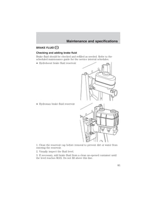
![Maintenance and specifications
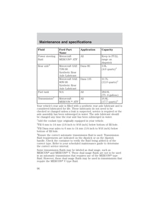
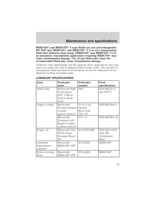
4. Use only a DOT 3 brake fluid certified to meet Ford specification
ESA-M6C25–A. Refer to Lubricant specifications in this chapter.
Brake fluid is toxic. If brake fluid contacts the eyes, flush eyes
with running water for 15 minutes. Seek medical attention if
irritation persists. If taken internally, drink water and induce vomiting.
Seek medical attention immediately.
If you use a brake fluid that is not DOT 3, you will cause
permanent damage to your brakes.
Do not let the reservoir for the master cylinder run dry. This
may cause the brakes to fail.
Brake system fluid should be replaced on a regular basis to maintain
optimum braking performance, especially under heavy-duty driving
conditions such as frequent steep grades or heavy towing loads. Refer to
the scheduled maintenance guide for the service interval schedules.
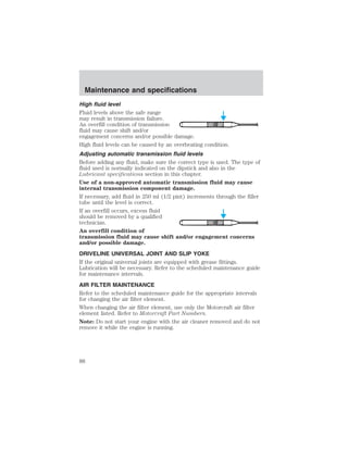
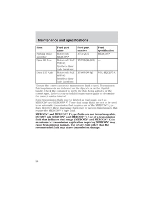
TRANSMISSION FLUID
Checking automatic transmission fluid (if equipped)
Refer to your scheduled maintenance guide for scheduled intervals for
fluid checks and changes. Your transmission does not consume fluid.
However, the fluid level should be checked if the transmission is not
working properly, i.e., if the transmission slips or shifts slowly or if you
notice some sign of fluid leakage.
Automatic transmission fluid expands when warmed. To obtain an
accurate fluid check, drive the vehicle until it is at normal operating
temperature (approximately 30 km [20 miles]). If your vehicle has been
operated for an extended period at high speeds, in city traffic during hot
weather or pulling a trailer, the vehicle should be turned off for about 30
minutes to allow fluid to cool before checking.
1. Drive the vehicle 30 km (20 miles) or until it reaches normal operating
temperature.
2. Park the vehicle on a level surface and engage the parking brake.
86](https://image.slidesharecdn.com/02f-53motorhome-140829050917-phpapp01/85/02-f-53-motorhome-86-320.jpg)
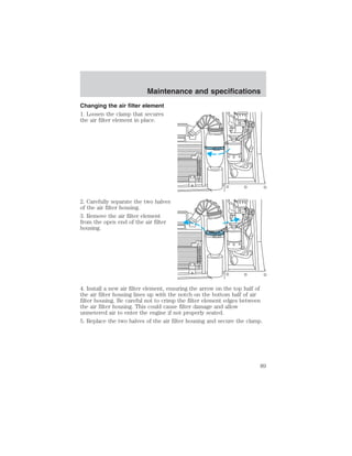
![Maintenance and specifications
3. With the parking brake engaged and your foot on the brake pedal,
start the engine and move the gearshift lever through all of the gear
ranges. Allow sufficient time for each gear to engage.
4. Latch the gearshift lever in P (Park) and leave the engine running.
5. Remove the dipstick, wiping it clean with a clean, dry lint free rag. If
necessary, refer to Identifying components in the engine compartment
in this chapter for the location of the dipstick.
6. Install the dipstick making sure it is fully seated in the filler tube.
7. Remove the dipstick and inspect the fluid level. The fluid should be in
the designated area for normal operating temperature or ambient
temperature.
Low fluid level
Do not drive the vehicle if the fluid
level is at the bottom of the dipstick
and the ambient temperature is
above 10°C (50°F).
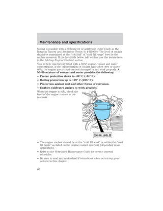
Correct fluid level
The transmission fluid should be checked at normal operating
temperature 66°C-77°C (150°F-170°F) on a level surface. The normal
operating temperature can be reached after approximately 30 km (20
miles) of driving.
You can check the fluid without driving if the ambient temperature is
above 10°C (50°F). However, if fluid is added at this time, an overfill
condition could result when the vehicle reaches normal operating
temperature.
The transmission fluid should be in
this range if at normal operating
temperature (66°C-77°C
[150°F-170°F]).
The transmission fluid should be in
this range if at ambient temperature
(10°C-35°C [50°F-95°F]).
87](https://image.slidesharecdn.com/02f-53motorhome-140829050917-phpapp01/85/02-f-53-motorhome-87-320.jpg)