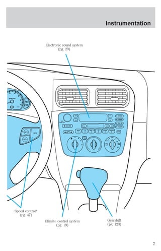
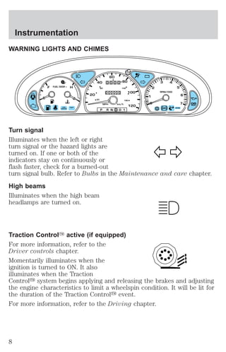
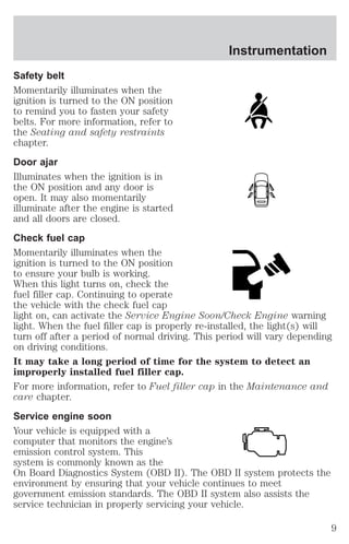
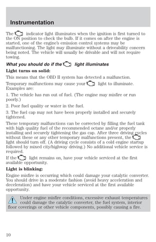
This document provides an overview of vehicle instrumentation, controls, features, and systems for a Ford vehicle. It includes descriptions of the instrument cluster, warning lights, driver controls, climate controls, seating, safety restraints, starting the vehicle, driving, roadside emergencies, vehicle maintenance, specifications, customer assistance, and reporting safety defects. The document also includes a glossary of common vehicle symbols that may be found in the vehicle.


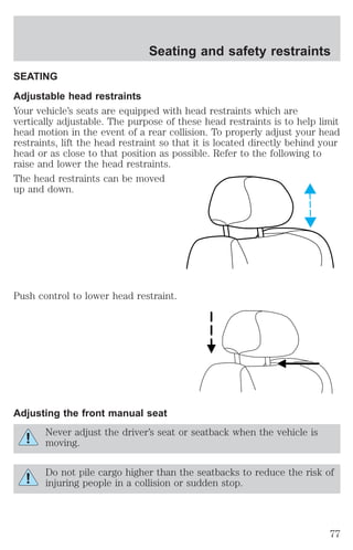
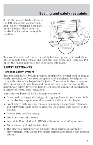
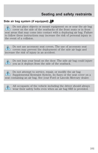
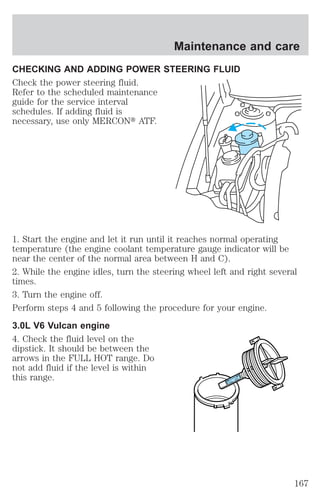
![Seating and safety restraints
Several air bag system
components get hot after
inflation. Do not touch them after
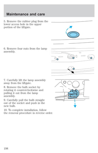
inflation.
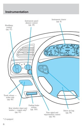
If the side air bag has
deployed, the air bag will
not function again. The side
air bag system (including the
seat) must be inspected and
serviced by a qualified
technician in accordance with
the vehicle service manual. If
the air bag is not replaced, the
unrepaired area will increase the
risk of injury in a collision.
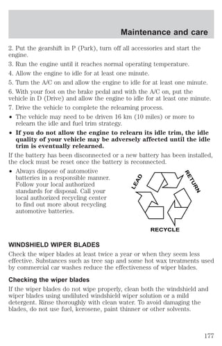
Disposal of air bags and air bag equipped vehicles
For disposal of air bags or air bag equipped vehicles, see your local
dealership or qualified technician. Air bags MUST BE disposed of by
qualified personnel.
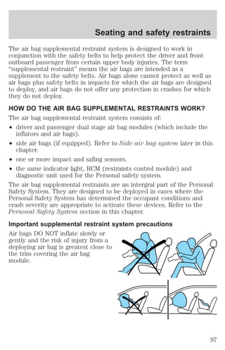
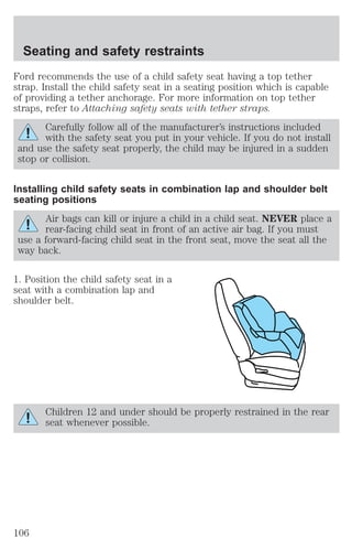
SAFETY RESTRAINTS FOR CHILDREN
See the following sections for directions on how to properly use safety
restraints for children. Also see Air Bag Supplemental Restraint
System (SRS) in this chapter for special instructions about using air
bags.
Important child restraint precautions
You are required by law to use safety restraints for children in the U.S.
and Canada. If small children ride in your vehicle (generally children who
are four years old or younger and who weigh 18 kg [40 lbs] or less), you
must put them in safety seats made especially for children. Check your
local and state or provincial laws for specific requirements regarding the
safety of children in your vehicle.
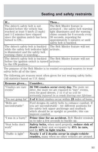
103](https://image.slidesharecdn.com/01sable-140831143528-phpapp02/85/01-sable-103-320.jpg)
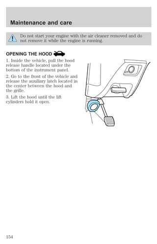
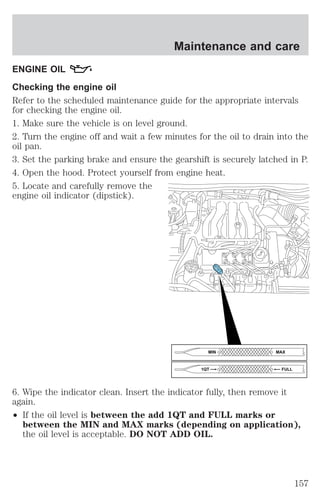
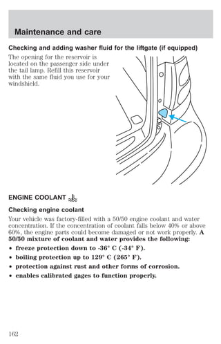
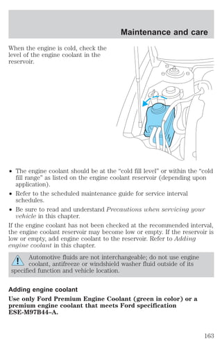
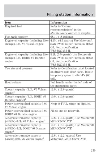
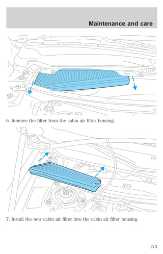
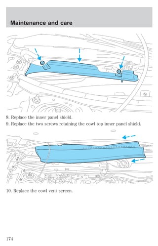
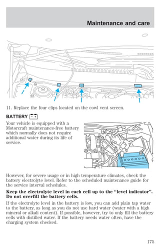
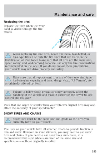
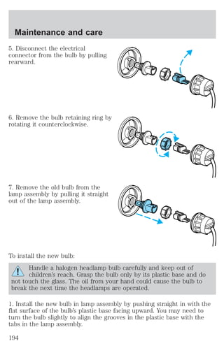
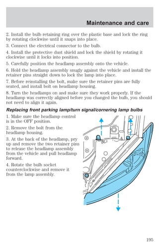
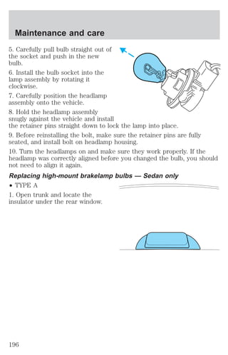
![Maintenance and care
Fill your engine coolant reservoir as outlined in Adding engine coolant
in this chapter.
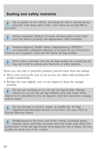
Severe climates
If you drive in extremely cold climates (less than –36° C [–34° F]):
² it may be necessary to increase the coolant concentration
above 50%.
² NEVER increase the coolant concentration above 60%.
² increased engine coolant concentrations above 60% will
decrease the overheat protection characteristics of the engine
coolant and may cause engine damage.
² refer to the chart on the coolant container to ensure the
coolant concentration in your vehicle will provide adequate
freeze protection at the temperatures in which you drive in the
winter months.
If you drive in extremely hot climates:
² it is still necessary to maintain the coolant concentration
above 40%.
² NEVER decrease the coolant concentration below 40%.
² decreased engine coolant concentrations below 40% will
decrease the corrosion protection characteristics of the engine
coolant and may cause engine damage.
² decreased engine coolant concentrations below 40% will
decrease the freeze protection characteristics of the engine
coolant and may cause engine damage.
² refer to the chart on the coolant container to ensure the
coolant concentration in your vehicle will provide adequate
protection at the temperatures in which you drive.
Vehicles driven year-round in non-extreme climates should use a 50/50
mixture of engine coolant and distilled water for optimum cooling system
and engine protection.
166](https://image.slidesharecdn.com/01sable-140831143528-phpapp02/85/01-sable-166-320.jpg)
![Maintenance and care
5. If the fluid is low, add fluid in small amounts, continuously checking
the level until it reaches the FULL HOT range. Be sure to put the
dipstick back in the reservoir.
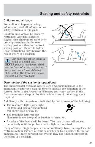
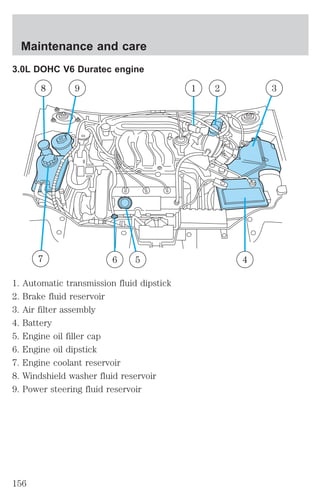
3.0L DOHC V6 Duratec engine
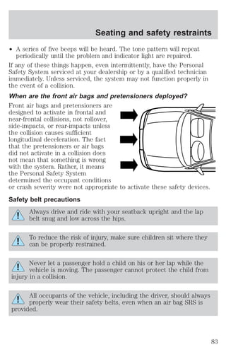
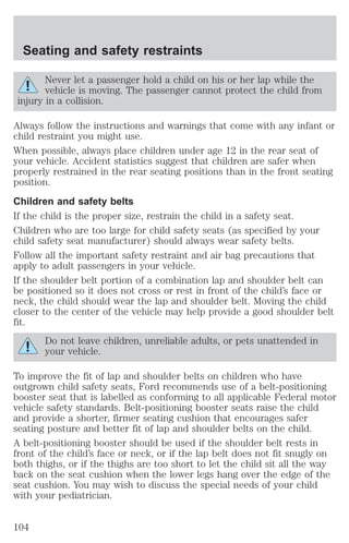
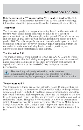
4. Check the fluid level in the
reservoir. It should be between the
MIN and MAX lines. Do not add
fluid if the level is within this range.
MAX
MIN
5. If the fluid is low, add fluid in small amounts, continuously checking
the level until it reaches the range between the MIN and MAX lines. Be
sure to put the cap back on the reservoir.
TRANSMISSION FLUID
Checking automatic transmission fluid
Refer to your scheduled maintenance guide for scheduled intervals for
fluid checks and changes. Your transaxle does not consume fluid.
However, the fluid level should be checked if the transaxle is not working
properly, i.e., if the transaxle slips or shifts slowly or if you notice some
sign of fluid leakage.
Automatic transmission fluid expands when warmed. To obtain an
accurate fluid check, drive the vehicle until it is warmed up
(approximately 30 km [20 miles]). If your vehicle has been
operated for an extended period at high speeds, in city traffic
during hot weather or pulling a trailer, the vehicle should be
turned off for about 30 minutes to allow fluid to cool before
checking.
1. Drive the vehicle 30 km (20 miles) or until it reaches normal operating
temperature.
2. Park the vehicle on a level surface and engage the parking brake.
168](https://image.slidesharecdn.com/01sable-140831143528-phpapp02/85/01-sable-168-320.jpg)
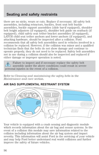
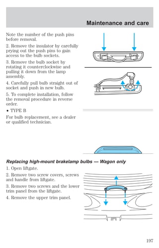
![Maintenance and care
3. With the parking brake engaged and your foot on the brake pedal,
start the engine and move the gearshift lever through all of the gear
ranges. Allow sufficient time for each gear to engage.
4. Latch the gearshift lever in P (Park) and leave the engine running.
5. Remove the dipstick, wiping it clean with a clean, dry lint free rag. If
necessary, refer to Identifying components in the engine compartment
in this chapter for the location of the dipstick.
6. Install the dipstick making sure it is fully seated in the filler tube.
7. Remove the dipstick and inspect the fluid level. The fluid should be in
the designated areas for normal operating temperature.
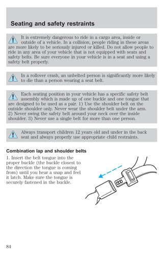
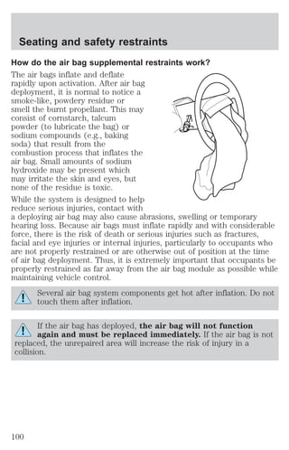
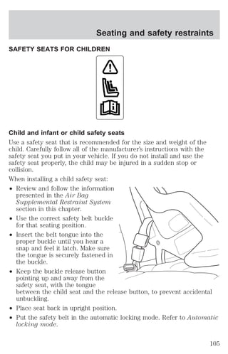
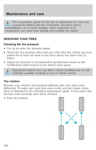
Low fluid level
Do not drive the vehicle if the fluid
level is at the bottom of the dipstick
and the outside temperatures are
DON’T ADD IF IN CROSSHATCH AREA--CHECH WHEN HOT-IDLING
above 10°C (50°F).
Correct fluid level
The transmission fluid should be checked at normal operating
temperatures 66°C-77°C (150°F-170°F) on a level surface. The normal
operating temperature can be reached after approximately 30 km (20
miles) of driving.
The transmission fluid should be in
this range if at normal operating
temperature (66°C-77°C
DON’T ADD IF IN CROSSHATCH AREA--CHECH WHEN HOT-IDLING
[150°F-170°F]).
High fluid level
Fluid levels above the safe range
may result in transaxle failure. An
overfill condition of transmission
DON’T ADD IF IN CROSSHATCH AREA--CHECH WHEN HOT-IDLING
fluid may cause shift and/or
engagement concerns and/or possible damage.
High fluid levels can be caused by an overheating condition.
Adjusting automatic transmission fluid levels
Before adding any fluid, make sure the correct type is used. The type of
fluid used is normally indicated on the dipstick and also in the
Lubricant specifications section in the Capacities and specifications
chapter.
169](https://image.slidesharecdn.com/01sable-140831143528-phpapp02/85/01-sable-169-320.jpg)
![² Sudden or hard accelerations may reduce fuel economy.
² Slow down gradually.
² Driving at reasonable speeds (traveling at 88 km/h [55 mph] uses 15%
less fuel than traveling at 105 km/h [65 mph]).
² Revving the engine before turning it off may reduce fuel economy.
² Using the air conditioner or defroster may reduce fuel economy.
² You may want to turn off the speed control in hilly terrain if
unnecessary shifting between third and fourth gear occurs.
Unnecessary shifting of this type could result in reduced fuel
economy.
² Warming up a vehicle on cold mornings is not required and may
reduce fuel economy.
² Resting your foot on the brake pedal while driving may reduce fuel
economy.
² Combine errands and minimize stop-and-go driving.
Maintenance
² Keep tires properly inflated and use only recommended size.
² Operating a vehicle with the wheels out of alignment will reduce fuel
economy.
² Use recommended engine oil. Refer to Lubricant Specifications.
² Perform all regularly scheduled maintenance items. Follow the
recommended maintenance schedule and owner maintenance checks
found in your vehicle scheduled maintenance guide.
Conditions
² Heavily loading a vehicle or towing a trailer may reduce fuel economy
at any speed.
² Carrying unnecessary weight may reduce fuel economy (approximately
0.4 km/L [1 mpg] is lost for every 180 kg [400 lb] of weight carried).
² Adding certain accessories to your vehicle (for example bug
deflectors, rollbars/light bars, running boards, ski/luggage racks) may
reduce fuel economy.
² Using fuel blended with alcohol may lower fuel economy.
² Fuel economy may decrease with lower temperatures during the first
12–16 km (8–10 miles) of driving.
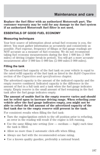
Maintenance and care
189](https://image.slidesharecdn.com/01sable-140831143528-phpapp02/85/01-sable-189-320.jpg)
![Customer assistance
For maximum vehicle performance, keep the following information in
mind when adding accessories or equipment to your vehicle:
² When adding accessories, equipment, passengers and luggage to your
vehicle, do not exceed the total weight capacity of the vehicle or of
the front or rear axle (GVWR or GAWR as indicated on the Safety
compliance certification label). Consult your dealer for specific weight
information.
² The Federal Communications Commission (FCC) and Canadian Radio
Telecommunications Commission (CRTC) regulate the use of mobile
communications systems - such as two-way radios, telephones and
theft alarms - that are equipped with radio transmitters. Any such
equipment installed in your vehicle should comply with FCC or CRTC
regulations and should be installed only by a qualified service
technician.
² Mobile communications systems may harm the operation of your
vehicle, particularly if they are not properly designed for automotive
use or are not properly installed. When operated, such systems may
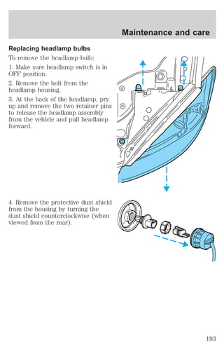
cause the engine to stumble or stall or cause the transmission to be
damaged or operate improperly. In addition, such systems may be
damaged or their performance may be affected by operating your
vehicle. (Citizens band [CB] transceivers, garage door openers and
other transmitters with outputs of five watts or less will not ordinarily
affect your vehicle’s operation.)
² Ford cannot assume responsibility for any adverse effects or damage
that may result from the use of such equipment.
ORDERING ADDITIONAL OWNER’S LITERATURE
To order the publications in this portfolio, contact Helm, Incorporated at:
HELM, INCORPORATED
P.O. Box 07150
Detroit, Michigan 48207
Or call:
For a free publication catalog, order toll free: 1-800-782-4356
Monday-Friday 8:00 a.m. - 6:00 p.m. EST,
for credit card holders only
228](https://image.slidesharecdn.com/01sable-140831143528-phpapp02/85/01-sable-228-320.jpg)