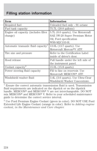
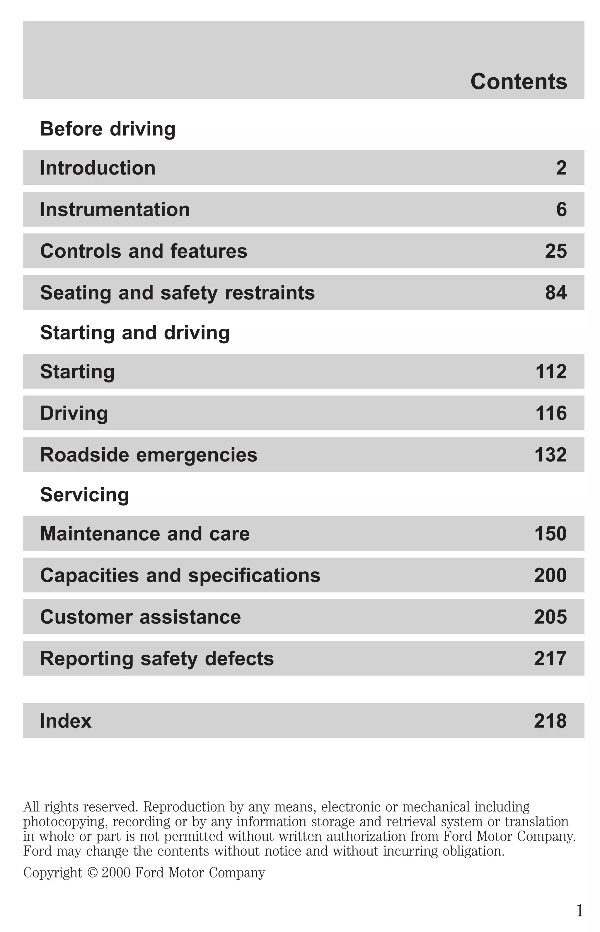
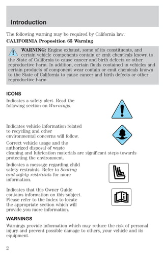
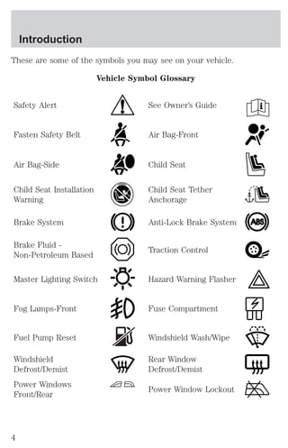
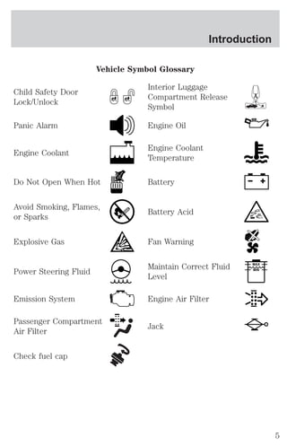
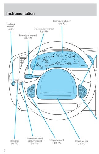
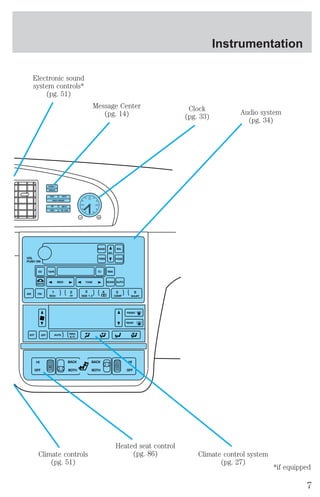
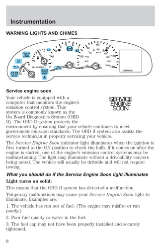
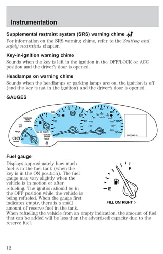
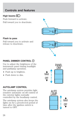
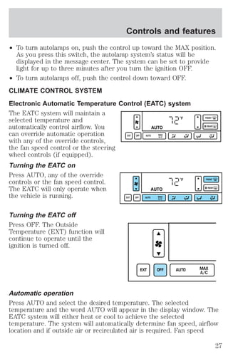
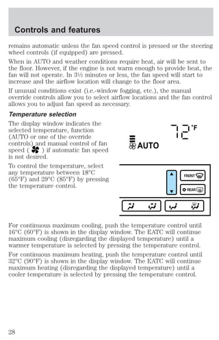
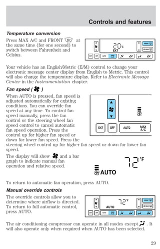
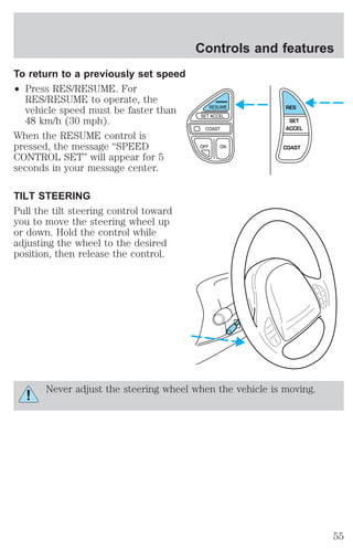
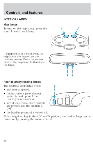
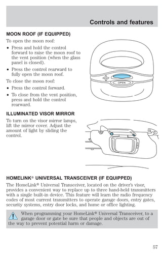
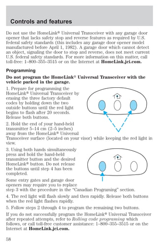
The document provides an overview of the features and controls of a vehicle. It includes sections on instrumentation, controls, seating and safety, starting and driving, servicing, and customer assistance. The instrumentation section describes the various gauges, lights, and warnings displayed to the driver. Controls and features outlines the headlights, turn signals, wipers, and other controls. Seating and safety restraints discusses seat adjustments and safety belts.

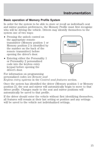
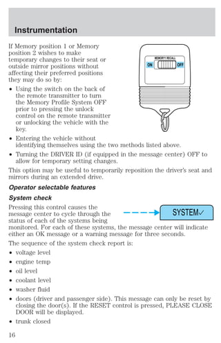
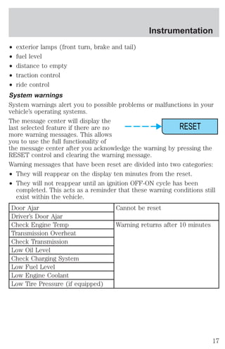
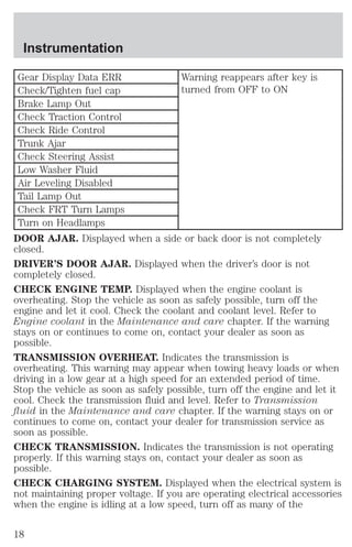
![Instrumentation
DRIVER ID (if equipped)
Press this control and use SELECT
to choose DRIVER 1 or DRIVER 2
when choosing operator selectable
features. Seat and mirror positions
and nine operator selectable features, found under the MENU and
VEHICLE HANDLING controls, will be saved to DRIVER 1 or DRIVER 2.
These will be automatically recalled when the drivers identify themselves
to the system with the remote entry transmitter (refer to Basic
Operation of Memory Profile System in this section) or selecting
DRIVER 1 or DRIVER 2 in the message center. When a vehicle setting is
changed, the message center will display “SAVED TO DRIVER 1 or
DRIVER 2” for 5 seconds to confirm the change has been made. Press
the SELECT to choose “OFF” for temporary position/setting changes
which will not be stored.
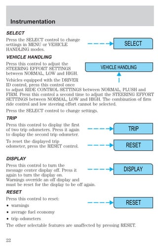
MENU
Press this control to change various
convenience settings throughout the
vehicle. Each press of the MENU
control will display the following:
² Traction control (returns to “ON” everytime vehicle is started).
² Express window (completely goes down with one touch on the power
switch).
DRIVER ID
MENU
² Auto lock (locks the doors when the vehicle reaches 5 km/h [3 mph]).
² Horn chirp (sounds horn one time whenever the doors are locked
using the remote transmitter).
² Seat access (moves seat back to aid entry/exit from the vehicle).
² Reverse mirrors (tilts the exterior mirrors downward to assist parking
using reverse).
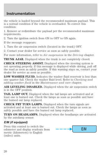
² English/metric (changes the odometer and display readouts)
Press the SELECT control to change the settings to ON or OFF.
These settings will be saved to the vehicle not individualized settings.
Vehicles equipped with the DRIVER ID control, the settings will be saved
to DRIVER 1 or DRIVER 2.
21](https://image.slidesharecdn.com/01continental-140831143446-phpapp02/85/01-continental-21-320.jpg)
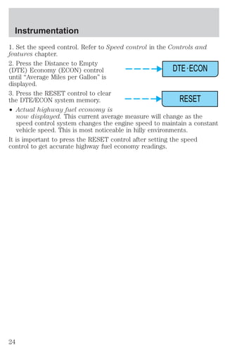
![DTE/ECON
² Press the DTE/ECON control
Instrumentation
DTE ECON
once to display approximately
how far you can drive before
running out of fuel, or the
distance to empty (DTE). To ensure accuracy, turn the ignition OFF
when you fill the tank.
² Press the DTE/ECON control a second time to display the average fuel
economy in liters/100 kilometers or miles/gallon, based on distance
traveled and rate of fuel used information.
² To reset this feature, press the
RESET control while average fuel
economy is displayed (while you
are driving).
RESET
The DTE function will flash for 5 seconds and sound a tone for 1 second
when you have approximately:
² 40 km (25 miles)
² 16 km (10 miles)
DTE is calculated using a running average fuel economy initialized by the
factory. This value is not the same as the average fuel economy display.
The running average fuel economy is based on more than 800 kilometers
(500 miles) of driving history, and is reinitialized if the battery is
disconnected.
If the FUEL LEVEL ERROR message is displayed, there is a problem
with the fuel indication system and you should contact your dealer for
service as soon as possible.
Checking your highway fuel economy using the electronic
message center display
The following procedure will allow you to accurately monitor your actual
highway fuel economy. Since this procedure requires the vehicle speed
control system to be set to highway speeds, it must be run only on
suitable roadways where long distance speed control can be safely
maintained.
You may notice gradual improvement in fuel economy over the course of
your vehicle’s break-in period (approximately 1 600 kilometers [1 000
miles]).
23](https://image.slidesharecdn.com/01continental-140831143446-phpapp02/85/01-continental-23-320.jpg)
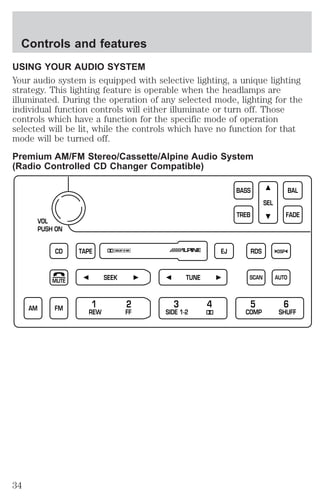
![Treble adjust
The treble adjust control allows you
to increase or decrease the audio
system’s treble output.
Speaker balance adjust
Speaker sound distribution can be
adjusted between the right and left
speakers.
Speaker fade adjust
Speaker sound can be adjusted
between the front and rear
speakers.
Tape/CD select (if equipped)
² To begin tape play (with a tape
loaded into the audio system)
while in the radio or CD mode,
press the TAPE control. Press the
button during rewind or fast forward to stop the rewind or fast
forward function.
² To begin CD play (if CD[s] are
loaded), press the CD control.
The first track of the disc will
begin playing. After that, CD play
will begin where it stopped last.
TREB SEL
BAL SEL
FADE SEL
TAPE
CD
Controls and features
40](https://image.slidesharecdn.com/01continental-140831143446-phpapp02/85/01-continental-40-320.jpg)
![Controls and features
Without moon roof:
1. Start the vehicle.
2. Press and hold the COMP side of
NW
the control for approximately six
seconds until “C” appears in the
COMP MIRROR
mirror display.
3. Drive the vehicle slowly (less
than 5 km/h [3 mph]) in circles or
on your everyday routine until the display reads a direction.
4. The compass is now calibrated.
With moon roof:
1. Start the vehicle.
2. Press and hold both map light
buttons for over 8 seconds, until the
letter “C” appears in the display,
then release.
3. Drive the vehicle slowly (less
than 8 km/h [5 mph]) in circles until the letter “C” display indicates a
direction.
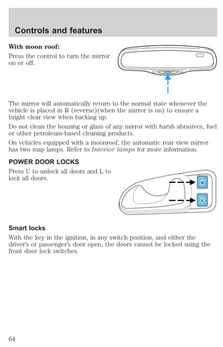
AUTOMATIC DIMMING REAR VIEW MIRROR
Your vehicle is equipped with inside and driver side outside rear view
mirrors with an auto-dimming function. The electronic day/night mirrors
will change from the normal state to the non-glare state when bright
lights (glare) reach the mirrors. When the inside rear view mirror detects
bright light from in front of or behind the vehicle, the inside and driver
side outside rear view mirrors will automatically adjust (darken) to
minimize glare.
Without moon roof:
Press the control to turn the mirror
on or off.
COMP MIRROR
63](https://image.slidesharecdn.com/01continental-140831143446-phpapp02/85/01-continental-63-320.jpg)
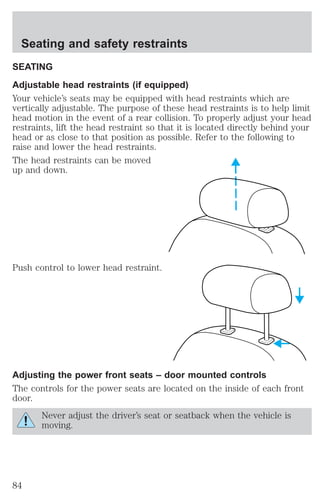
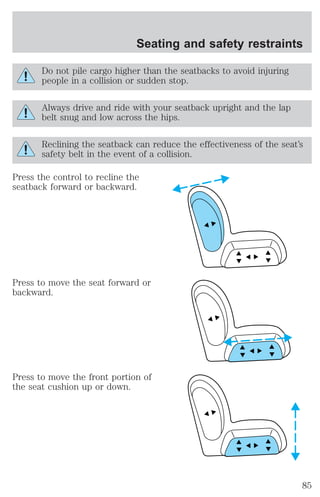
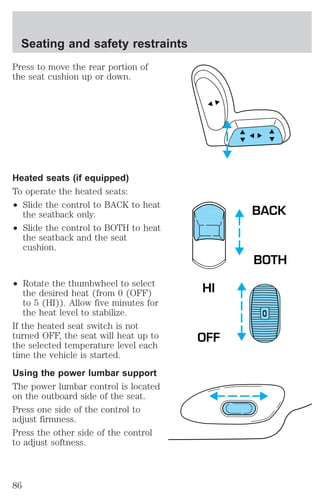
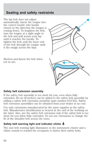
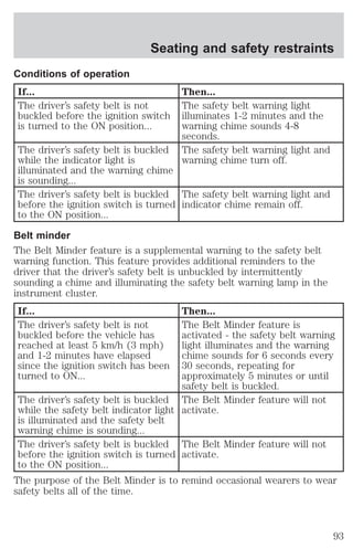
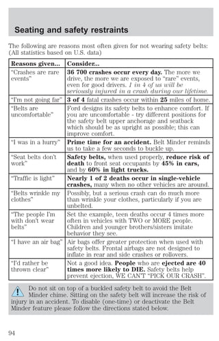
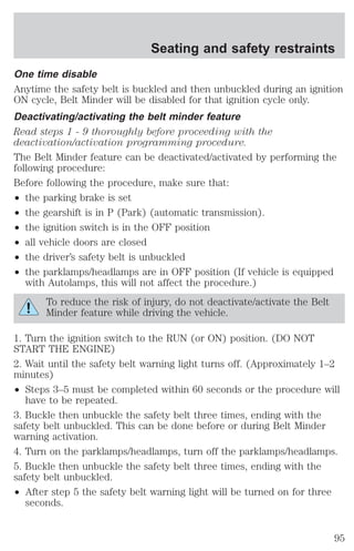
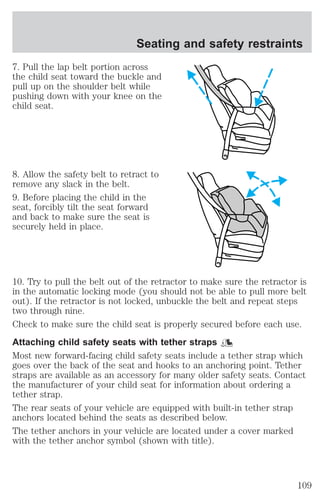
![Seating and safety restraints
If any of these things happen, even intermittently, have the SRS serviced
at your dealership or by a qualified technician immediately. Unless
serviced, the system may not function properly in the event of a collision.
Disposal of air bags and air bag equipped vehicles (including
pretensioners)
For disposal of air bags or air bag equipped vehicles, see your local
dealership or qualified technician. Air bags MUST BE disposed of by
qualified personnel.
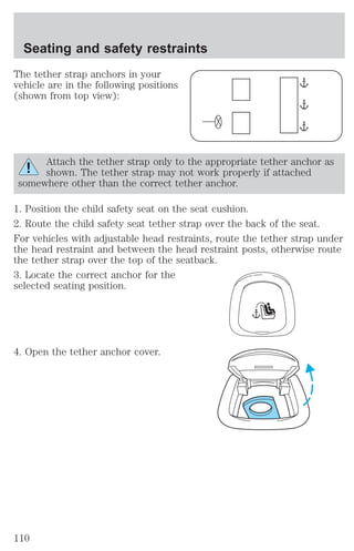
SAFETY RESTRAINTS FOR CHILDREN
See the following sections for directions on how to properly use safety
restraints for children. Also see Air Bag Supplemental Restraint System
(SRS) in this chapter for special instructions about using air bags.
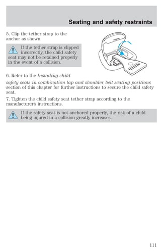
Important child restraint precautions
You are required by law to use safety restraints for children in the U.S.
and Canada. If small children ride in your vehicle (generally children who
are four years old or younger and who weigh 18 kg [40 lbs] or less), you
must put them in safety seats made especially for children. Check your
local and state or provincial laws for specific requirements regarding the
safety of children in your vehicle.
Never let a passenger hold a child on his or her lap while the
vehicle is moving. The passenger cannot protect the child from
injury in a collision.
Always follow the instructions and warnings that come with any infant or
child restraint you might use.
When possible, always place children under age 12 in the rear seat of
your vehicle. Accident statistics suggest that children are safer when
properly restrained in the rear seating positions than in the front seating
position.
Children and safety belts
If the child is the proper size, restrain the child in a safety seat.
Children who are too large for child safety seats (as specified by your
child safety seat manufacturer) should always wear safety belts.
104](https://image.slidesharecdn.com/01continental-140831143446-phpapp02/85/01-continental-104-320.jpg)
![Driving
Always ensure that the weight of passengers, cargo and equipment being
carried is within the weight limitations that have been established for
your vehicle including both gross vehicle weight and Front and rear
gross axle weight rating limits. Under no circumstance should these
limitations be exceeded. Exceeding any vehicle weight rating limitation
could result in serious damage to the vehicle and/or personal injury.
TRAILER TOWING
Your vehicle is classified as a light duty towing vehicle. Refer to the
following chart for towing limits:
Towing class Light duty
Maximum gross trailer weight - kg (lbs.) 454 (1 000)*
Maximum tongue load - kg (lbs.) 45/68 (100/150)
Engine 4.6L
Hitch design Load carrying type
Trailer-tow package option Not required
* Vehicle speed should not exceed 72 km/h (45 mph) when towing on
grades. Limit maximum gross trailer weight to 454 kg (1 000 lbs.) and
maximum tongue load to 45/68 kg (100/150 lbs.): (1) when you are
towing a trailer on steep hills or on moderate hills for distances longer
than 8 km (5 miles) or more and; (2) on very hot days (when the
temperature is above 38°C [100°F])
Your vehicle does not come from the factory fully equipped to tow.
However, you can contact your local Lincoln dealer to get the proper
towing equipment. Do not tow a trailer until your vehicle has been
driven at least 3 200 km (2 000 miles).
Towing a trailer places an additional load on your vehicle’s engine,
transmission, brakes, tires and suspension. Inspect these components
carefully after towing.
Do not tow a trailer when using a temporary spare tire.
Do not exceed the GVWR or the GAWR specified on the
certification label.
128](https://image.slidesharecdn.com/01continental-140831143446-phpapp02/85/01-continental-128-320.jpg)
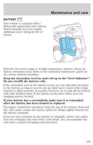
![Maintenance and care
Always dispose of used automotive fluids in a responsible manner.
Follow your community’s regulations and standards for recycling and
disposing of automotive fluids.
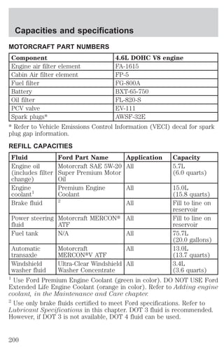
Coolant refill capacity
To find out how much fluid your vehicle’s cooling system can hold, refer
to Refill capacities in the Capacities and specifications chapter.
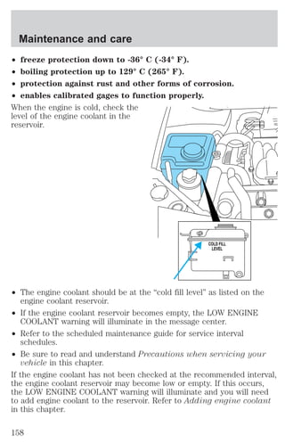
Fill your engine coolant reservoir as outlined in Adding engine coolant
in this chapter.
Severe climates
If you drive in extremely cold climates (less than –36° C [–34° F]):
² it may be necessary to increase the coolant concentration
above 50%.
² NEVER increase the coolant concentration above 60%.
² increased engine coolant concentrations above 60% will
decrease the overheat protection characteristics of the engine
coolant and may cause engine damage.
² refer to the chart on the coolant container to ensure the
coolant concentration in your vehicle will provide adequate
freeze protection at the temperatures in which you drive in the
winter months.
If you drive in extremely hot climates:
² it is still necessary to maintain the coolant concentration
above 40%.
² NEVER decrease the coolant concentration below 40%.
² decreased engine coolant concentrations below 40% will
decrease the corrosion protection characteristics of the engine
coolant and may cause engine damage.
² decreased engine coolant concentrations below 40% will
decrease the freeze protection characteristics of the engine
coolant and may cause engine damage.
² refer to the chart on the coolant container to ensure the
coolant concentration in your vehicle will provide adequate
protection at the temperatures in which you drive.
161](https://image.slidesharecdn.com/01continental-140831143446-phpapp02/85/01-continental-161-320.jpg)
![Maintenance and care
TRANSMISSION FLUID
Checking automatic transmission fluid
Refer to your scheduled maintenance guide for scheduled intervals for
fluid checks and changes. Your transaxle does not consume fluid.
However, the fluid level should be checked if the transaxle is not working
properly, i.e., if the transaxle slips or shifts slowly or if you notice some
sign of fluid leakage.
Automatic transmission fluid expands when warmed. To obtain an
accurate fluid check, drive the vehicle until it is warmed up
(approximately 30 km [20 miles]). If your vehicle has been
operated for an extended period at high speeds, in city traffic
during hot weather or pulling a trailer, the vehicle should be
turned off for about 30 minutes to allow fluid to cool before
checking.
1. Drive the vehicle 30 km (20 miles) or until it reaches normal operating
temperature.
2. Park the vehicle on a level surface and engage the parking brake.
3. With the parking brake engaged and your foot on the brake pedal,
start the engine and move the gearshift lever through all of the gear
ranges. Allow sufficient time for each gear to engage.
4. Latch the gearshift lever in P (Park) and leave the engine running.
5. Remove the dipstick, wiping it clean with a clean, dry lint free rag. If
necessary, refer to Identifying components in the engine compartment
in this chapter for the location of the dipstick.
6. Install the dipstick making sure it is fully seated in the filler tube.
7. Remove the dipstick and inspect the fluid level. The fluid should be in
the designated areas for normal operating temperature.
Low fluid level
Do not drive the vehicle if the fluid
level is at the bottom of the dipstick
and the outside temperatures are
DON’T ADD IF IN CROSSHATCH AREA--CHECH WHEN HOT-IDLING
above 10°C (50°F).
163](https://image.slidesharecdn.com/01continental-140831143446-phpapp02/85/01-continental-163-320.jpg)
![Correct fluid level
The transmission fluid should be checked at normal operating
temperatures 66°C-77°C (150°F-170°F) on a level surface. The normal
operating temperature can be reached after approximately 30 km (20
miles) of driving.
The transmission fluid should be in
this range if at normal operating
temperature (66°C-77°C
DON’T ADD IF IN CROSSHATCH AREA--CHECH WHEN HOT-IDLING
[150°F-170°F]).
High fluid level
Fluid levels above the safe range
may result in transaxle failure. An
overfill condition of transmission
DON’T ADD IF IN CROSSHATCH AREA--CHECH WHEN HOT-IDLING
fluid may cause shift and/or
engagement concerns and/or possible damage.
High fluid levels can be caused by an overheating condition.
Adjusting automatic transmission fluid levels
Before adding any fluid, make sure the correct type is used. The type of
fluid used is normally indicated on the dipstick and also in the
Lubricant specifications section in the Capacities and specifications
chapter.
Use of a non-approved automatic transmission fluid may cause
internal transaxle component damage.
If necessary, add fluid in 250 mL (1/2 pint) increments through the filler
tube until the level is correct.
If an overfill occurs, excess fluid
should be removed by a qualified
technician.
DON’T ADD IF IN CROSSHATCH AREA--CHECH WHEN HOT-IDLING
An overfill condition of
transmission fluid may cause shift and/or engagement concerns
and/or possible damage.
Maintenance and care
164](https://image.slidesharecdn.com/01continental-140831143446-phpapp02/85/01-continental-164-320.jpg)

![² Sudden or hard accelerations may reduce fuel economy.
² Slow down gradually.
² Driving at reasonable speeds (traveling at 88 km/h [55 mph] uses 15%
less fuel than traveling at 105 km/h [65 mph]).
² Revving the engine before turning it off may reduce fuel economy.
² Using the air conditioner or defroster may reduce fuel economy.
² You may want to turn off the speed control in hilly terrain if
unnecessary shifting between third and fourth gear occurs.
Unnecessary shifting of this type could result in reduced fuel
economy.
² Warming up a vehicle on cold mornings is not required and may
reduce fuel economy.
² Resting your foot on the brake pedal while driving may reduce fuel
economy.
² Combine errands and minimize stop-and-go driving.
Maintenance
² Keep tires properly inflated and use only recommended size.
² Operating a vehicle with the wheels out of alignment will reduce fuel
economy.
² Use recommended engine oil. Refer to Lubricant Specifications.
² Perform all regularly scheduled maintenance items. Follow the
recommended maintenance schedule and owner maintenance checks
found in your vehicle scheduled maintenance guide.
Conditions
² Heavily loading a vehicle or towing a trailer may reduce fuel economy
at any speed.
² Carrying unnecessary weight may reduce fuel economy (approximately
0.4 km/L [1 mpg] is lost for every 180 kg [400 lb] of weight carried).
² Adding certain accessories to your vehicle (for example bug
deflectors, rollbars/light bars, running boards, ski/luggage racks) may
reduce fuel economy.
² Using fuel blended with alcohol may lower fuel economy.
² Fuel economy may decrease with lower temperatures during the first
12–16 km (8–10 miles) of driving.
Maintenance and care
183](https://image.slidesharecdn.com/01continental-140831143446-phpapp02/85/01-continental-183-320.jpg)

![Customer assistance
² Mobile communications systems may harm the operation of your
vehicle, particularly if they are not properly designed for automotive
use or are not properly installed. When operated, such systems may
cause the engine to stumble or stall or cause the transmission to be
damaged or operate improperly. In addition, such systems may be
damaged or their performance may be affected by operating your
vehicle. (Citizens band [CB] transceivers, garage door openers and
other transmitters with outputs of five watts or less will not ordinarily
affect your vehicle’s operation.)
² Ford cannot assume responsibility for any adverse effects or damage
that may result from the use of such equipment.
ORDERING ADDITIONAL OWNER’S LITERATURE
To order the publications in this portfolio:
Make checks payable to:
HELM, INCORPORATED
P.O. Box 07150
Detroit, Michigan 48207
For a free publication catalog, order toll free: 1-800-782-4356
Monday-Friday 8:00 a.m. - 6:00 p.m. EST,
for credit card holders only
Obtaining a French owner’s guide
French Owner’s Guides can be obtained from your dealer or by writing to
Ford Motor Company of Canada, Limited, Service Publications, P.O. Box
1580, Station B, Mississauga, Ontario L4Y 4G3.
215](https://image.slidesharecdn.com/01continental-140831143446-phpapp02/85/01-continental-215-320.jpg)