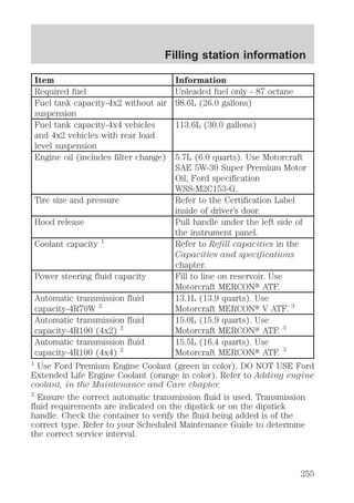
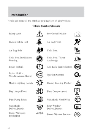
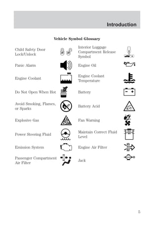
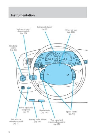
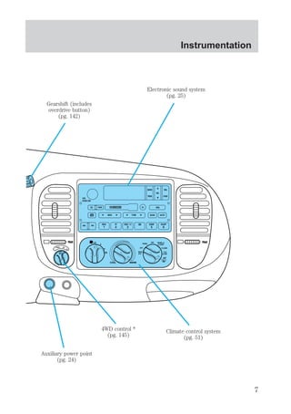
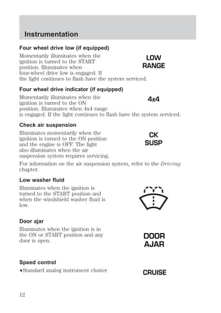
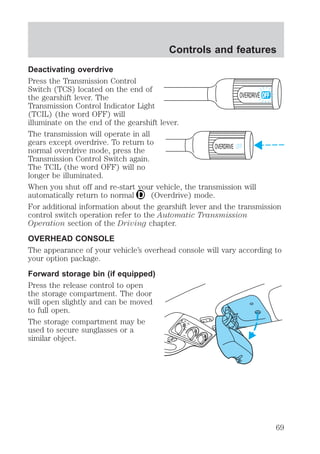
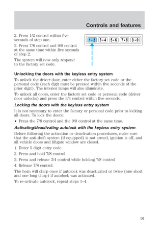
This document provides an overview of the instrumentation, controls, features, and systems of a vehicle. It includes descriptions of the dashboard components, warning lights, gauges, climate controls, and 4-wheel drive system. It also outlines what to do if warning lights illuminate and provides safety information for drivers.

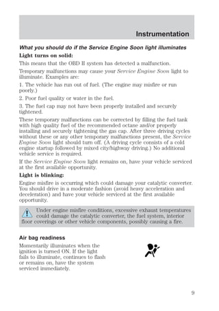
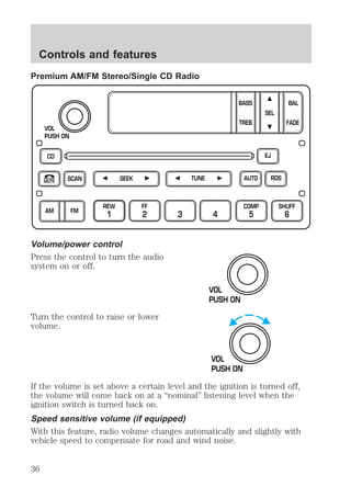
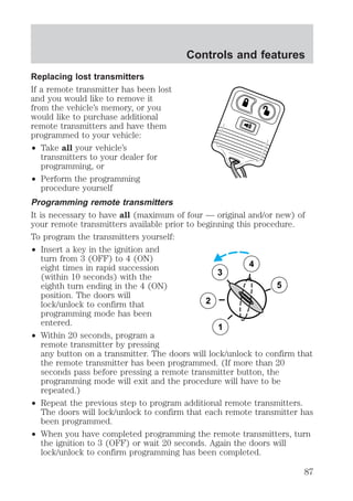
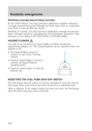
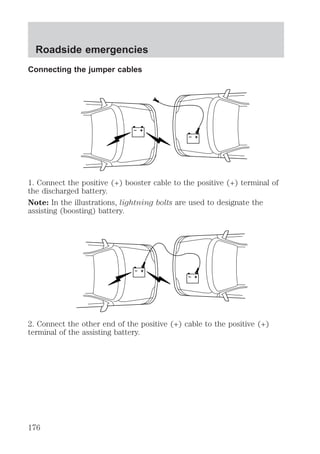
![Controls and features
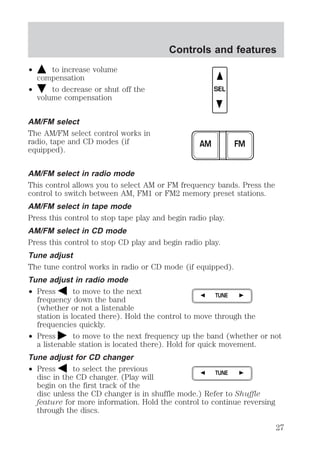
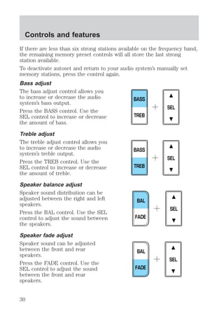
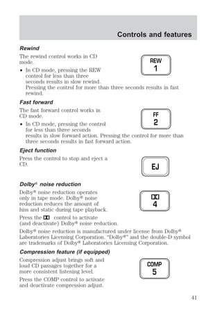
Bass adjust
The bass adjust control allows you
to increase or decrease the audio
system’s bass output.
Treble adjust
The treble adjust control allows you
to increase or decrease the audio
system’s treble output.
Speaker balance adjust
Speaker sound distribution can be
adjusted between the right and left
speakers.
Speaker fade adjust
Speaker sound can be adjusted
between the front and rear
speakers.
SEL
BASS
TREB
SEL
BASS
TREB
SEL
BAL
FADE
SEL
BAL
FADE
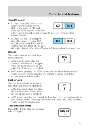
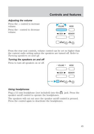
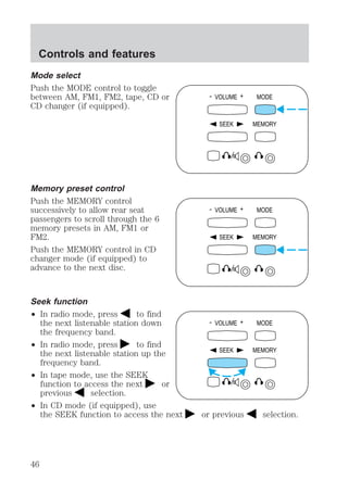
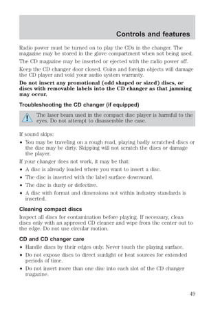
CD select
To begin CD play (if CD[s] are loaded), press the CD control. The first
track of the disc will begin playing. After that, CD play will begin where
it stopped last. Press the CD control again to toggle between CD and CD
changer mode (if equipped).
40](https://image.slidesharecdn.com/00expedition-140904144508-phpapp02/85/00-expedition-40-320.jpg)
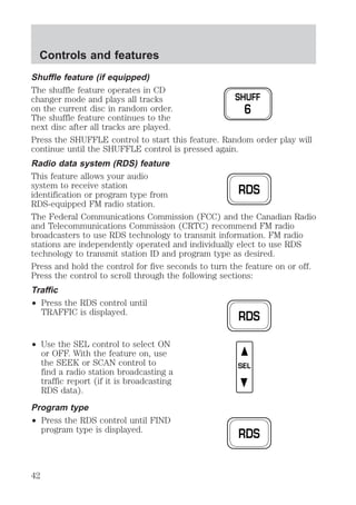
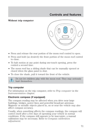
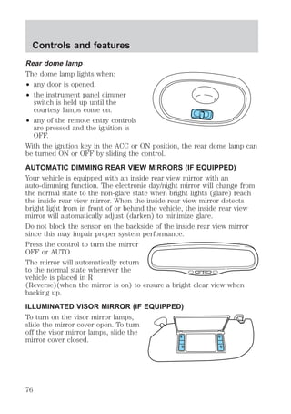
![Without trip computer
1. Press and hold the SELECT
control until VAR appears in the
display, then release. The display
should show the current zone
number.
2. Press the SELECT control until
the desired zone number appears.
The display will flash and then
return to normal operation. The
zone is now updated.
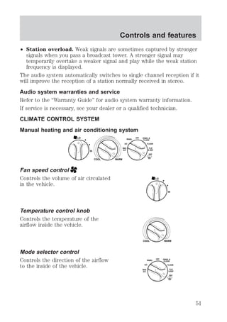
Controls and features
AUTO
ROOF
CAL
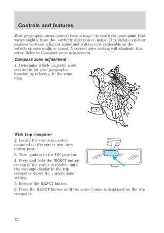
Compass calibration adjustment
Perform this adjustment in an open area free from steel structures and
high voltage lines.
For optimum calibration, turn off all electrical accessories (heater/air
conditioning, wipers, etc.) and make sure all vehicle doors are shut.
1. Start the vehicle.
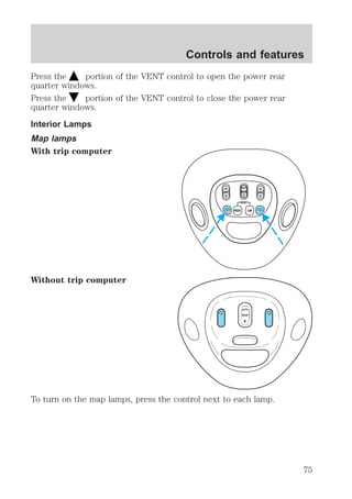
With trip computer
2. Press and hold the RESET button
on the compass module until CAL
indicator is displayed in the trip
computer.
3. Release pressure from the RESET
button.
4. Slowly drive the vehicle in a
circle (less than 5 km/h [3 mph])
until the CAL indicator turns off.
This will take three to five circles to complete calibration.
5. The compass is now calibrated.
73](https://image.slidesharecdn.com/00expedition-140904144508-phpapp02/85/00-expedition-73-320.jpg)
![Without trip computer
1. Press and hold the SELECT
control until CAL appears in the
display (approximately eight
seconds) and release.
2. Drive the vehicle slowly (less
than 5 km/h [3 mph]) in circles until
CAL indicator turns off in about 2–3
complete circles.
3. The compass is now calibrated.
Power quarter rear windows (if equipped)
² With out a moon roof
² With a moon roof
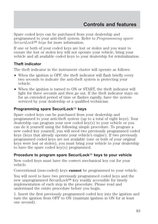
AUTO
ROOF
CAL
VENT VENT
MODE E/M
RESET
VENT ROOF VENT
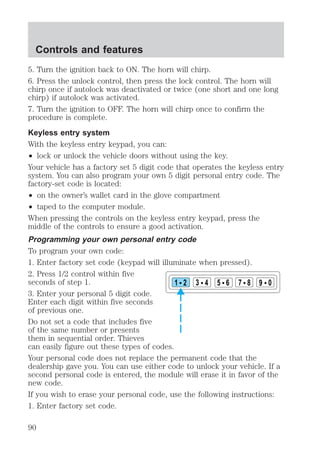
Controls and features
74](https://image.slidesharecdn.com/00expedition-140904144508-phpapp02/85/00-expedition-74-320.jpg)
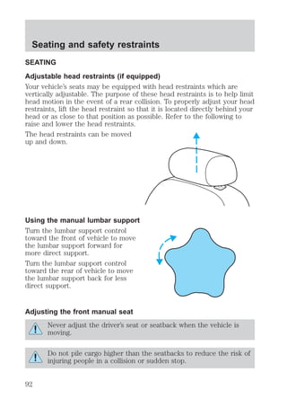
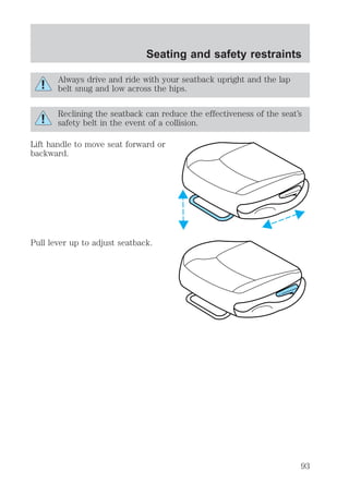
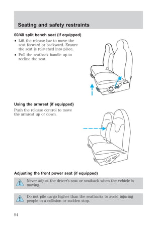
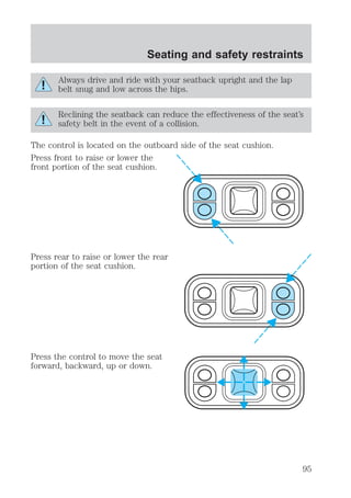
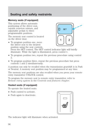
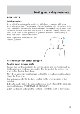
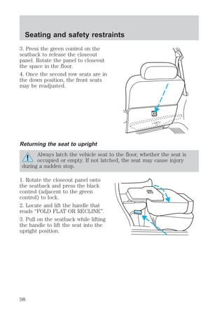
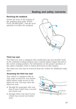
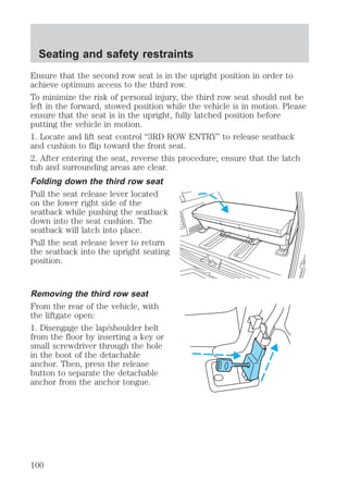
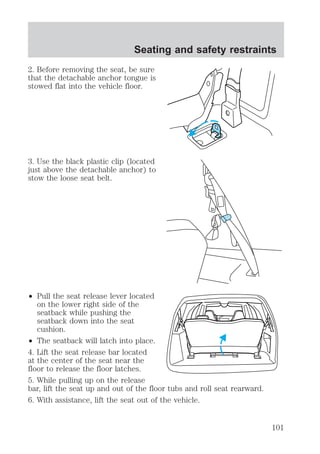
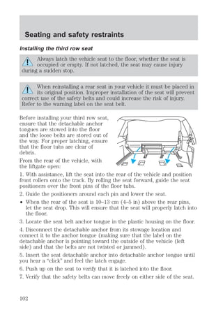
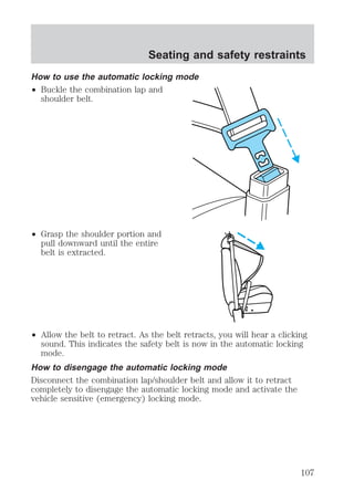
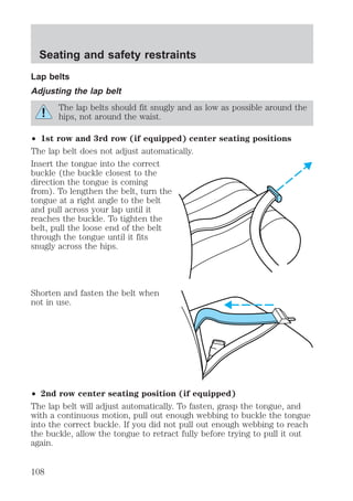
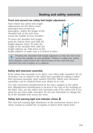
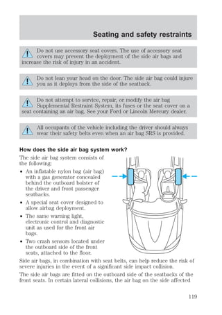
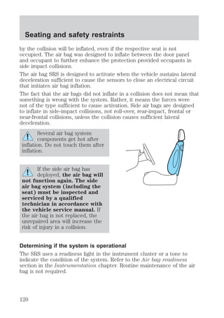
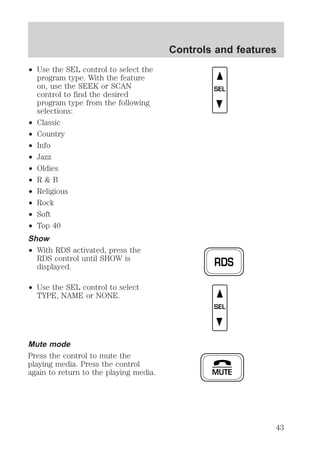
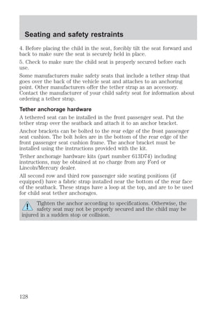
![Seating and safety restraints
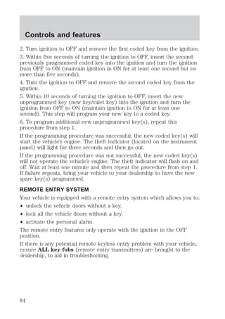
A difficulty with the system is indicated by one or more of the following:
² The readiness light (same light as for front air bag system) will either
flash or stay lit.
² The readiness light will not illuminate immediately after ignition is
turned on.
² A series of five beeps will be heard. The tone pattern will repeat
periodically until the problem and light are repaired.
If any of these things happen, even intermittently, have the SRS serviced
at your dealership or by a qualified technician immediately. Unless
serviced, the system may not function properly in the event of a
collision.
Disposal of air bags and air bag equipped vehicles
For disposal of air bags or air bag equipped vehicles, see your local
dealership or qualified technician. Air bags MUST BE disposed of by
qualified personnel.
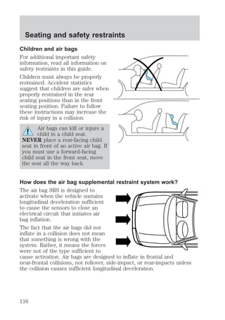
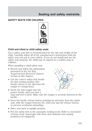
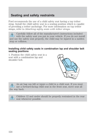
SAFETY RESTRAINTS FOR CHILDREN
See the following sections for directions on how to properly use safety
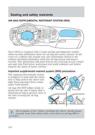
restraints for children. Also see Air Bag Supplemental Restraint
System (SRS) in this chapter for special instructions about using air
bags.
Important child restraint precautions
You are required by law to use safety restraints for children in the U.S.
and Canada. If small children ride in your vehicle (generally children who
are four years old or younger and who weigh 18 kg [40 lbs] or less), you
must put them in safety seats made especially for children. Check your
local and state or provincial laws for specific requirements regarding the
safety of children in your vehicle.
Never let a passenger hold a child on his or her lap while the
vehicle is moving. The passenger cannot protect the child from
injury in a collision.
Always follow the instructions and warnings that come with any infant or
child restraint you might use.
When possible, always place children under age 12 in the rear seat of
your vehicle. Accident statistics suggest that children are safer when
121](https://image.slidesharecdn.com/00expedition-140904144508-phpapp02/85/00-expedition-121-320.jpg)
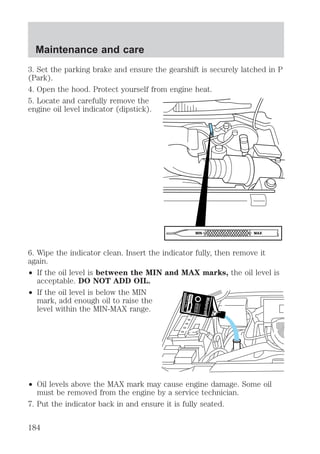
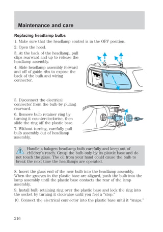
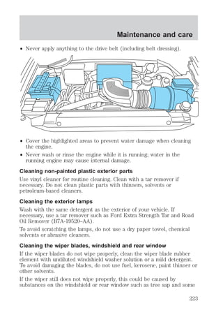
![Maintenance and care
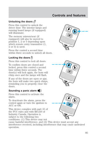
Recycled engine coolant
Ford Motor Company recommends the use of a recycled engine coolant
produced by Ford-approved processes.
Not all coolant recycling processes produce coolant which meets Ford
specification ESE-M97B44-A. Use of a recycled engine coolant which
does not meet the Ford specification may harm engine and cooling
system components.
Always dispose of used automotive fluids in a responsible manner.
Follow your community’s regulations and standards for recycling and
disposing of automotive fluids.
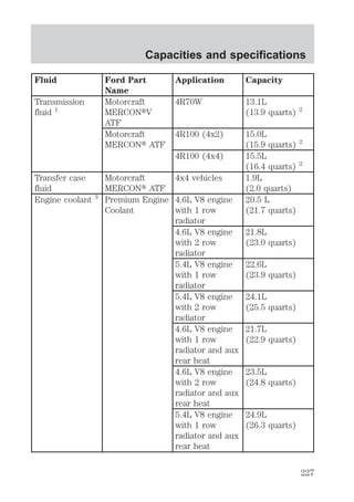
Coolant refill capacity
To find out how much fluid your vehicle’s cooling system can hold, refer
to Refill capacities in the Capacities and specifications chapter.
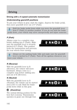
Fill your engine coolant reservoir as outlined in Adding engine coolant
in this chapter.
Severe climates
If you drive in extremely cold climates (less than –36° C [–34° F]):
² it may be necessary to increase the coolant concentration
above 50%.
² NEVER increase the coolant concentration above 60%.
² increased engine coolant concentrations above 60% will
decrease the overheat protection characteristics of the engine
coolant and may cause engine damage.
² refer to the chart on the coolant container to ensure the
coolant concentration in your vehicle will provide adequate
freeze protection at the temperatures in which you drive in the
winter months.
If you drive in extremely hot climates:
² it is still necessary to maintain the coolant concentration
above 40%.
² NEVER decrease the coolant concentration below 40%.
² decreased engine coolant concentrations below 40% will
decrease the corrosion protection characteristics of the engine
coolant and may cause engine damage.
191](https://image.slidesharecdn.com/00expedition-140904144508-phpapp02/85/00-expedition-191-320.jpg)

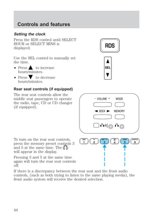
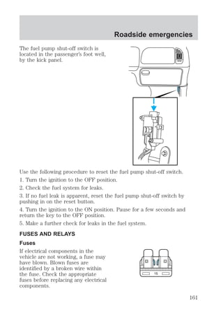
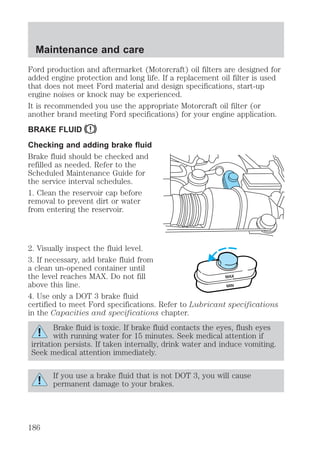
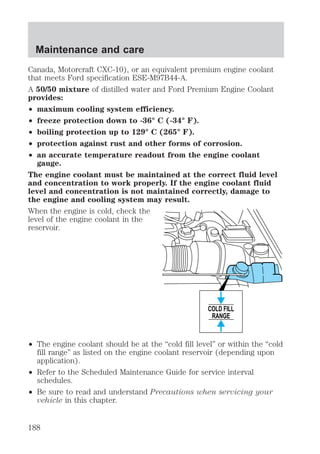
![Maintenance and care
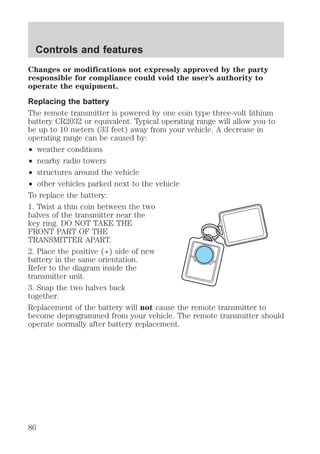
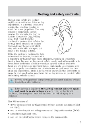
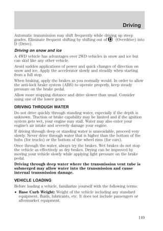
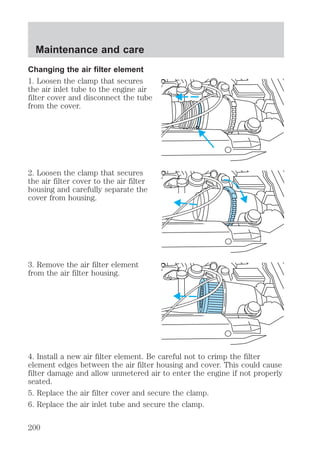
4. Check the fluid level in the
reservoir. It should be between the
MIN and MAX lines. Do not add
fluid if the level is in this range.
5. If the fluid is low, add fluid in
small amounts, continuously
checking the level until it reaches
the range between the MIN and
MAX lines. Be sure to put the cap
back on the reservoir.
MAX
MIN
MAX
MIN
TRANSMISSION FLUID
Checking automatic transmission fluid
Refer to your Scheduled Maintenance Guide for scheduled intervals for
fluid checks and changes. Your transmission does not consume fluid.
However, the fluid level should be checked if the transmission is not
working properly, i.e., if the transmission slips or shifts slowly or if you
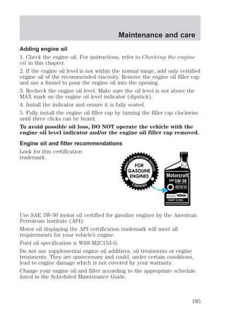
notice some sign of fluid leakage.
Automatic transmission fluid expands when warmed. To obtain an
accurate fluid check, drive the vehicle until it is at normal operating
temperature (approximately 30 km [20 miles]). If your vehicle has been
operated for an extended period at high speeds, in city traffic during hot
weather or pulling a trailer, the vehicle should be turned off for about 30
minutes to allow fluid to cool before checking.
1. Drive the vehicle 30 km (20 miles) or until it reaches normal operating
temperature.
2. Park the vehicle on a level surface and engage the parking brake.
3. With the parking brake engaged and your foot on the brake pedal,
start the engine and move the gearshift lever through all of the gear
ranges. Allow sufficient time for each gear to engage.
4. Latch the gearshift lever in P (Park) and leave the engine running.
194](https://image.slidesharecdn.com/00expedition-140904144508-phpapp02/85/00-expedition-194-320.jpg)
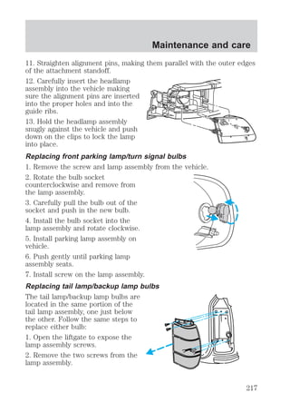
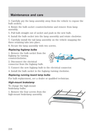
![Maintenance and care
5. Remove the dipstick, wiping it clean with a clean, dry lint free rag. If
necessary, refer to Identifying components in the engine compartment
in this chapter for the location of the dipstick.
6. Install the dipstick making sure it is fully seated in the filler tube.
7. Remove the dipstick and inspect the fluid level. The fluid should be in
the designated area for normal operating temperature or ambient
temperature.
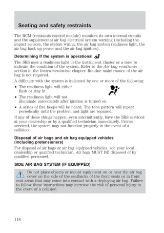
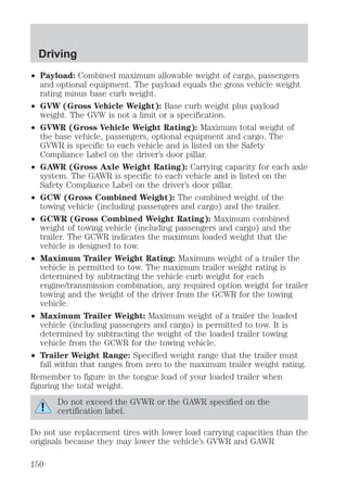
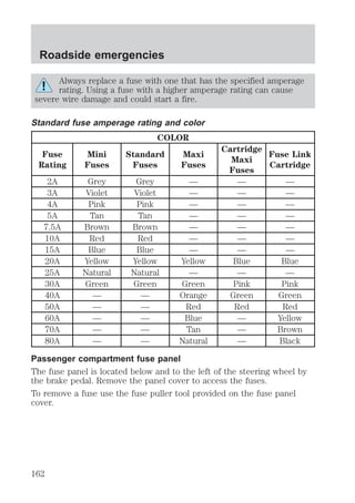
Low fluid level
Do not drive the vehicle if the fluid
level is at the bottom of the dipstick
and the ambient temperature is
DON’T ADD
above 10°C (50°F).
ADD COLD HOT DO NOT ADD
Correct fluid level
The transmission fluid should be checked at normal operating
temperature 66°C-77°C (150°F-170°F) on a level surface. The normal
operating temperature can be reached after approximately 30 km (20
miles) of driving.
You can check the fluid without driving if the ambient temperature is
above 10°C (50°F). However, if fluid is added at this time, an overfill
condition could result when the vehicle reaches normal operating
temperature.
The transmission fluid should be in
this range if at normal operating
temperature (66°C-77°C
[150°F-170°F]).
DON’T ADD
ADD COLD HOT DO NOT ADD
195](https://image.slidesharecdn.com/00expedition-140904144508-phpapp02/85/00-expedition-195-320.jpg)
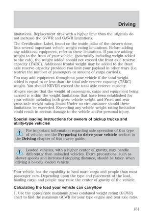
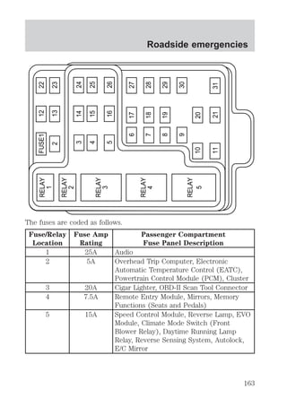
![The transmission fluid should be in
this range if at ambient temperature
(10°C-35°C [50°F-95°F]).
DON’T ADD
ADD COLD HOT DO NOT ADD
High fluid level
Fluid levels above the safe range
may result in transmission failure.
An overfill condition of transmission
DON’T ADD
fluid may cause shift and/or
engagement concerns and/or
possible damage.
High fluid levels can be caused by
ADD COLD HOT DO NOT ADD
an overheating condition.
Adjusting automatic transmission fluid levels
Before adding any fluid, make sure the correct type is used. The type of
fluid used is normally indicated on the dipstick and also in the
Lubricant specifications section in the Capacities and specifications
chapter.
Use of a non-approved automatic transmission fluid may cause
internal transmission component damage.
If necessary, add fluid in 250 mL (1/2 pint) increments through the filler
tube until the level is correct.
If an overfill occurs, excess fluid
should be removed by a qualified
technician.
DON’T ADD
An overfill condition of
transmission fluid may cause
shift and/or engagement
concerns and/or possible
ADD COLD HOT DO NOT ADD
damage.
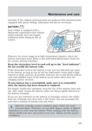
DRIVELINE UNIVERSAL JOINT AND SLIP YOKE
Your vehicle may be equipped with universal joints that require
lubrication. Refer to the Scheduled Maintenance Guide for maintenance
Maintenance and care
196](https://image.slidesharecdn.com/00expedition-140904144508-phpapp02/85/00-expedition-196-320.jpg)
![Maintenance and care
Driving style — good driving and fuel economy habits
Give consideration to the lists that follow and you may be able to change
a number of variables and improve your fuel economy.
Habits
² Smooth, moderate operation can yield up to 10% savings in fuel.
² Steady speeds without stopping will usually give the best fuel
economy.
² Idling for long periods of time (greater than one minute) may waste
fuel.
² Anticipate stopping; slowing down may eliminate the need to stop.
² Sudden or hard accelerations may reduce fuel economy.
² Slow down gradually.
² Driving at reasonable speeds (traveling at 88 km/h [55 mph] uses 15%
less fuel than traveling at 105 km/h [65 mph]).
² Revving the engine before turning it off may reduce fuel economy.
² Using the air conditioner or defroster may reduce fuel economy.
² You may want to turn off the speed control in hilly terrain if
unnecessary shifting between third and fourth gear occurs.
Unnecessary shifting of this type could result in reduced fuel
economy.
² Warming up a vehicle on cold mornings is not required and may
reduce fuel economy.
² Resting your foot on the brake pedal while driving may reduce fuel
economy.
² Combine errands and minimize stop-and-go driving.
Maintenance
² Keep tires properly inflated and use only recommended size.
² Operating a vehicle with the wheels out of alignment will reduce fuel
economy.
² Use recommended engine oil. Refer to Lubricant Specifications.
212](https://image.slidesharecdn.com/00expedition-140904144508-phpapp02/85/00-expedition-212-320.jpg)
![Maintenance and care
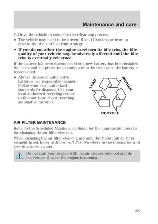
² Perform all regularly scheduled maintenance items. Follow the
recommended maintenance schedule and owner maintenance checks
found in your vehicle Scheduled Maintenance Guide.
Conditions
² Heavily loading a vehicle or towing a trailer may reduce fuel economy
at any speed.
² Carrying unnecessary weight may reduce fuel economy (approximately
0.4 km/L [1 mpg] is lost for every 180 kg [400 lb] of weight carried).
² Adding certain accessories to your vehicle (for example bug
deflectors, rollbars/light bars, running boards, ski/luggage racks) may
reduce fuel economy.
² Using fuel blended with alcohol may lower fuel economy.
² Fuel economy may decrease with lower temperatures during the first
12–16 km (8–10 miles) of driving.
² Driving on flat terrain offers improved fuel economy as compared to
driving on hilly terrain.
² Transmissions give their best fuel economy when operated in the top
cruise gear and with steady pressure on the gas pedal.
² Four-wheel-drive operation (if equipped) is less fuel efficient than
two-wheel-drive operation.
² Close windows for high speed driving.
EPA window sticker
Every new vehicle should have the EPA window sticker. Contact your
dealer if the window sticker is not supplied with your vehicle. The EPA
window sticker should be your guide for the fuel economy comparisons
with other vehicles.
It is important to note the box in the lower left corner of the window
sticker. These numbers represent the Range of L/100 km (MPG)
expected on the vehicle under optimum conditions. Your fuel economy
may vary depending upon the method of operation and conditions.
EMISSION CONTROL SYSTEM
Your vehicle is equipped with various emission control components and a
catalytic converter which will enable your vehicle to comply with
applicable exhaust emission standards. To make sure that the catalytic
213](https://image.slidesharecdn.com/00expedition-140904144508-phpapp02/85/00-expedition-213-320.jpg)
![Customer assistance
cause the engine to stumble or stall. In addition, such systems may be
damaged or their performance may be affected by operating your
vehicle. (Citizens band [CB] transceivers, garage door openers and
other transmitters with outputs of five watts or less will not ordinarily
affect your vehicle’s operation.)
² Ford cannot assume responsibility for any adverse effects or damage
that may result from the use of such equipment.
ORDERING ADDITIONAL OWNER’S LITERATURE
To order the publications in this portfolio:
Make checks payable to:
HELM, INCORPORATED
P.O. Box 07150
Detroit, Michigan 48207
For a free publication catalog, order toll free: 1-800-782-4356
Monday-Friday 8:00 a.m. - 6:00 p.m. EST,
for credit card holders only
Obtaining a French owner’s guide
French Owner’s Guides can be obtained from your dealer or by writing to
Ford Motor Company of Canada, Limited, Service Publications, P.O. Box
1580, Station B, Mississauga, Ontario L4Y 4G3.
246](https://image.slidesharecdn.com/00expedition-140904144508-phpapp02/85/00-expedition-246-320.jpg)