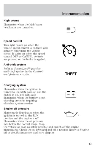
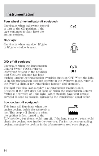
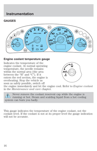
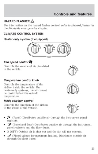
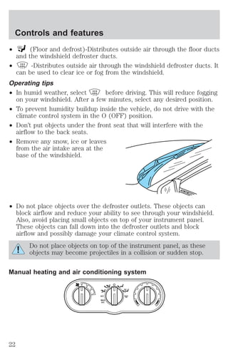
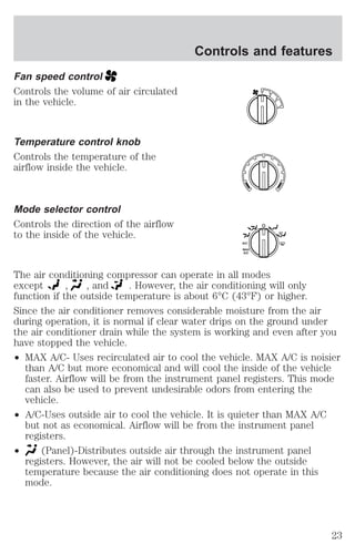
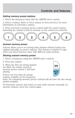
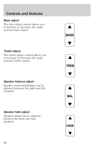
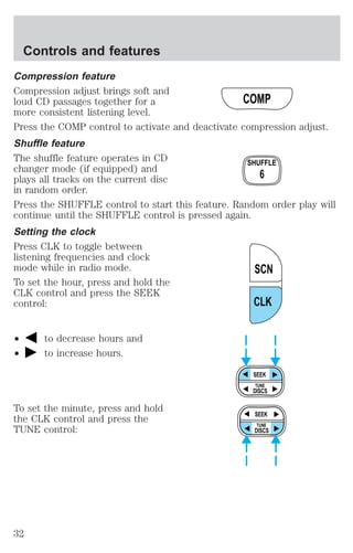
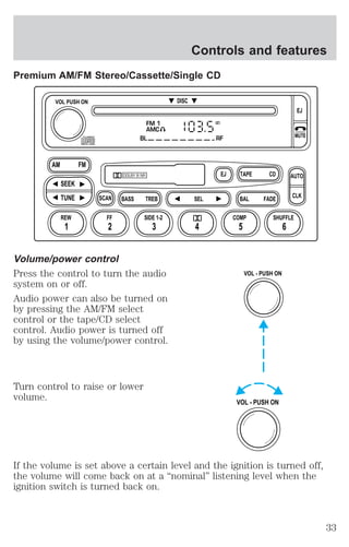
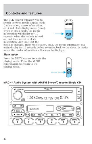
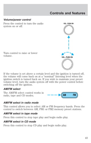
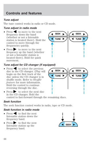
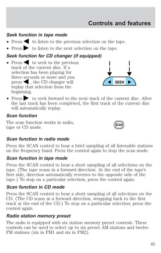
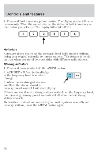
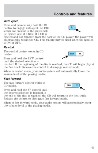
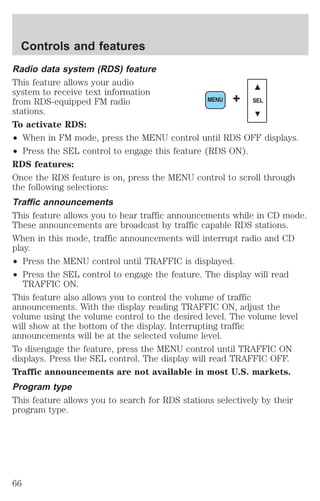
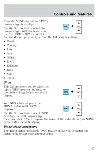
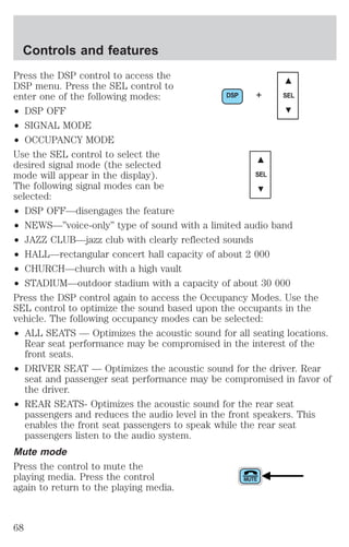
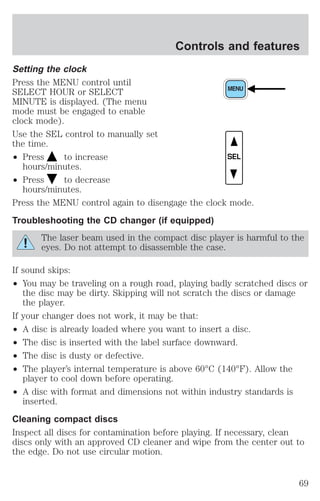
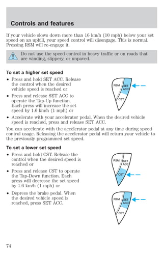
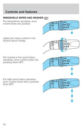
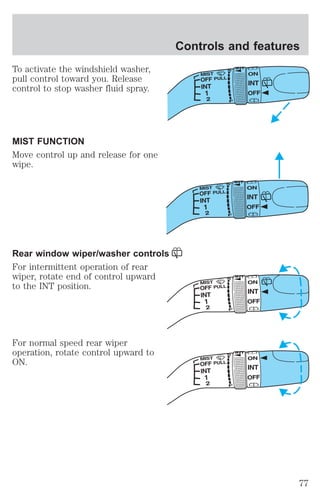
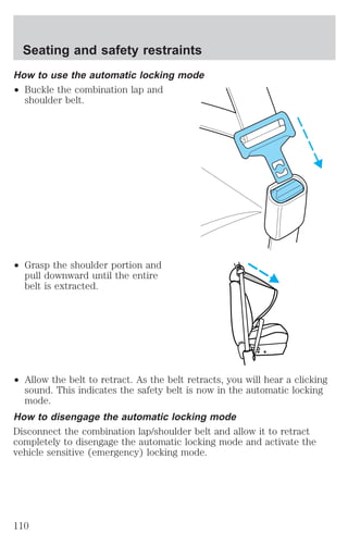
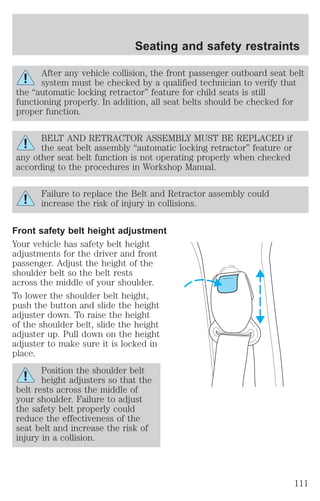
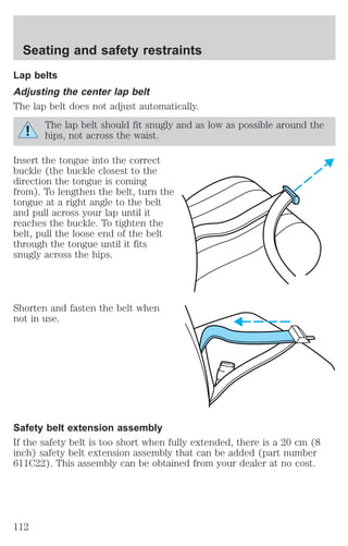
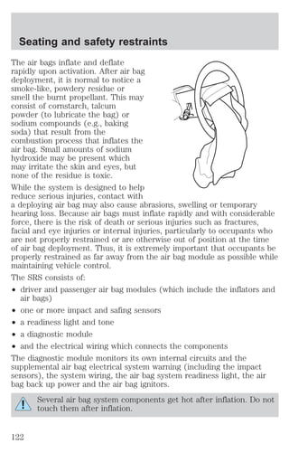
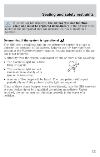
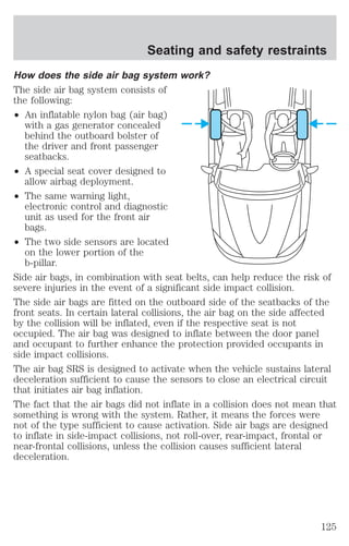
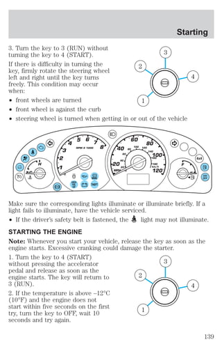
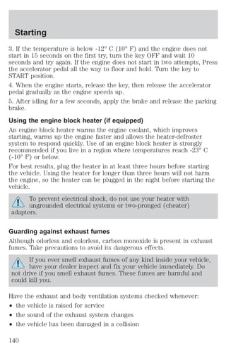
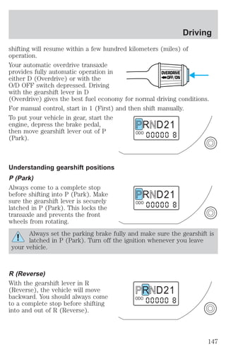
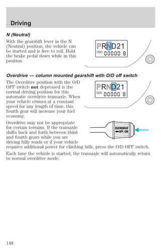
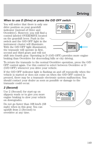
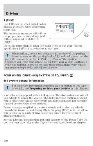
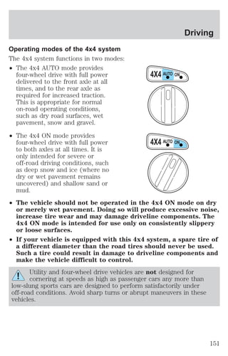
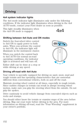
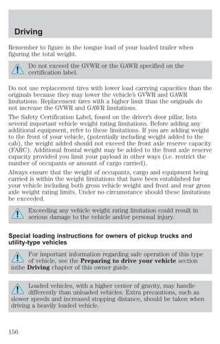
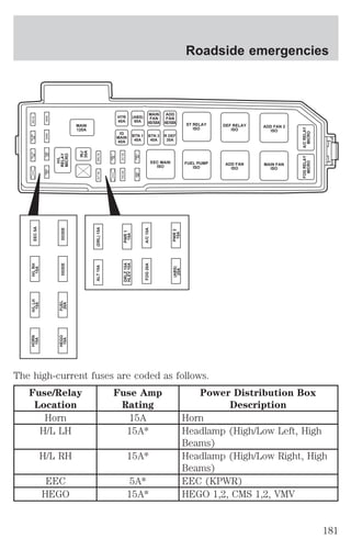
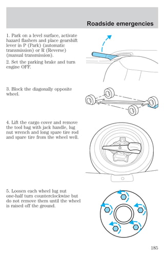
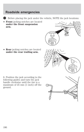
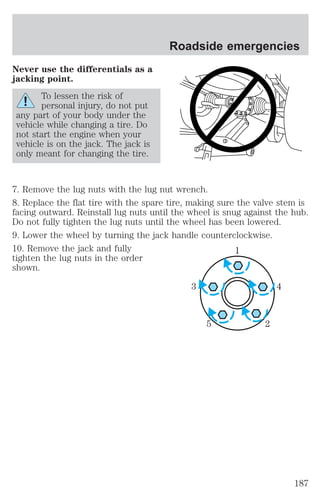
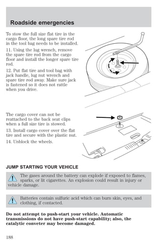
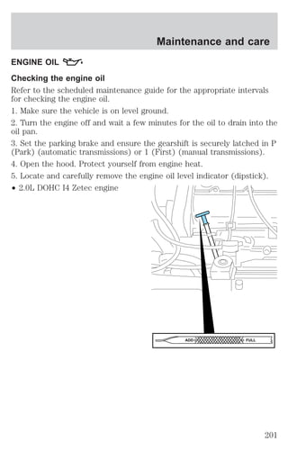
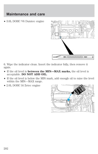
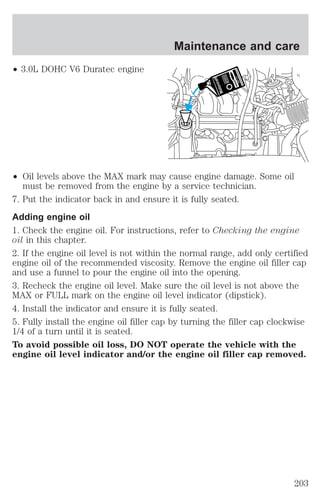
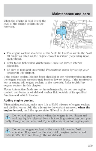
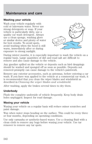
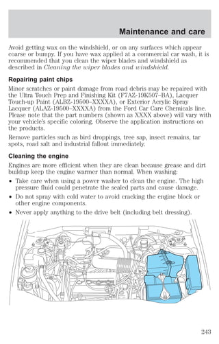
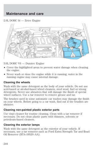
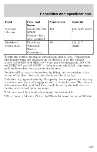
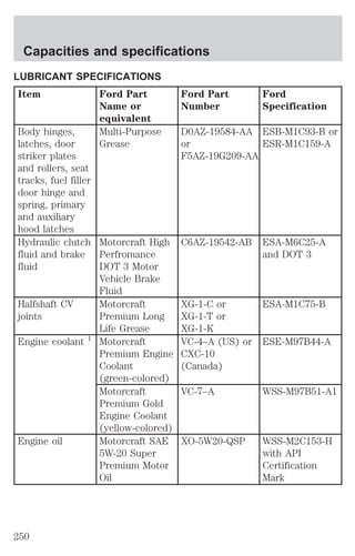
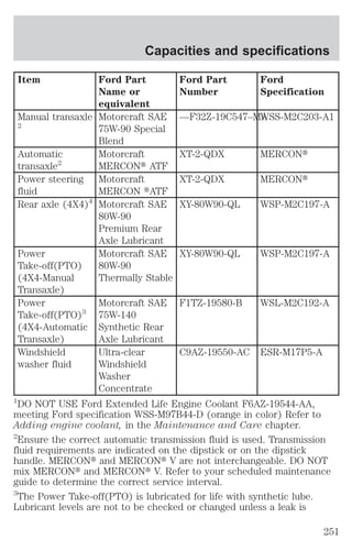
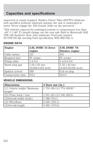
This document provides an overview of instrumentation, controls, and features for a vehicle. It includes descriptions and functions for various buttons, gauges, lights, and vehicle systems. Safety and operational information is also presented. The document contains detailed explanations to help the driver understand and properly operate the vehicle.
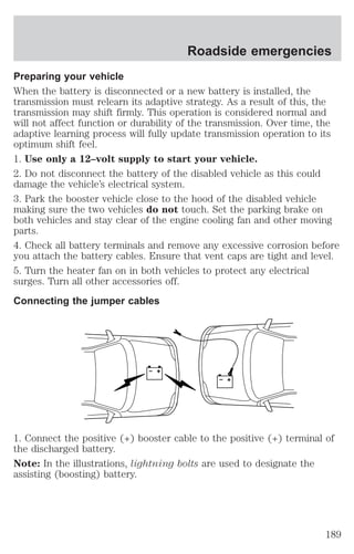
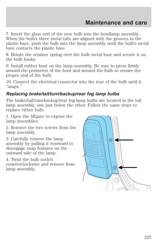
![Controls and features
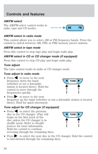
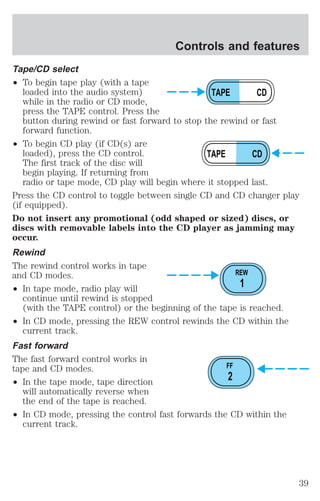
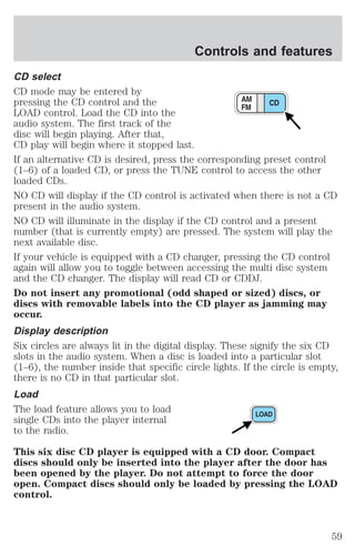
CD select
To begin CD play (if CD[s] are
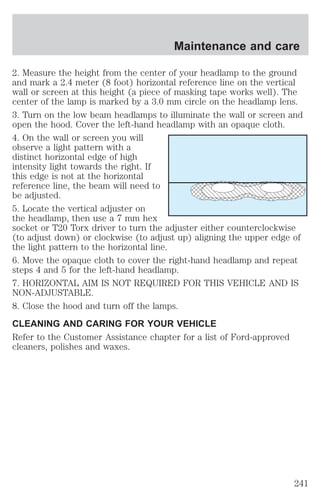
loaded), press the CD control. The
AM
first track of the disc will begin
FM
playing. After that, CD play will
begin where it stopped last. Press
CD
the control again to begin CD
changer play (if equipped).
Do not insert any promotional (odd shaped or sized) discs, or
discs with removable labels into the CD player as jamming may
occur.
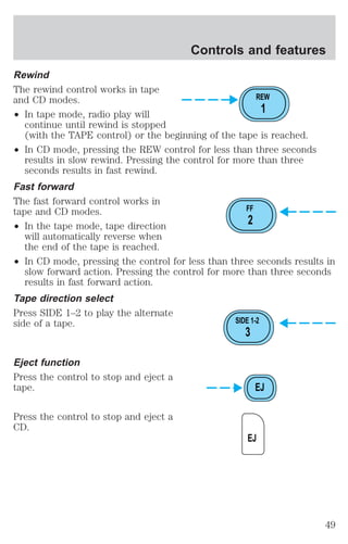
Rewind
The rewind control works in CD and CD changer (if equipped) modes.
To rewind in CD mode press the CD
CD
control (preset 1).
1
Pressing the control for less than
three seconds results in slow
rewind. Pressing the control for more than three seconds results in fast
rewind.
Fast forward
The fast forward control works in CD mode.
To fast forward in CD mode, press
CD
the CD control (preset 2).
2
Pressing the control for less than
three seconds results in slow
forward action. Pressing the control for more than three seconds results
in fast forward action.
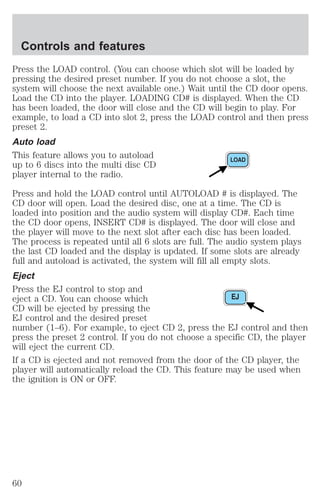
Eject function
Press the control to stop and eject a
CD.
EJ
31](https://image.slidesharecdn.com/01escape-140831143452-phpapp01/85/01-escape-31-320.jpg)
![Seating and safety restraints
Disposal of air bags and air bag equipped vehicles (including
pretensioners)
For disposal of air bags or air bag equipped vehicles, see your local
dealership or qualified technician. Air bags MUST BE disposed of by
qualified personnel.
SAFETY RESTRAINTS FOR CHILDREN
See the following sections for directions on how to properly use safety
restraints for children. Also see Air bag supplemental restraint system
(SRS) in this chapter for special instructions about using air bags.
Important child restraint precautions
You are required by law to use safety restraints for children in the U.S.
and Canada. If small children ride in your vehicle (generally children who
are four years old or younger and who weigh 18 kg [40 lbs] or less), you
must put them in safety seats made especially for children. Check your
local and state or provincial laws for specific requirements regarding the
safety of children in your vehicle.
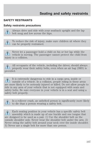
Never let a passenger hold a child on his or her lap while the
vehicle is moving. The passenger cannot protect the child from
injury in a collision.
Always follow the instructions and warnings that come with any infant or
child restraint you might use.
When possible, always place children under age 12 in the rear seat of
your vehicle. Accident statistics suggest that children are safer when
properly restrained in the rear seating positions than in the front seating
position.
Children and safety belts
If the child is the proper size, restrain the child in a safety seat.
Children who are too large for child safety seats (as specified by your
child safety seat manufacturer) should always wear safety belts.
Follow all the important safety restraint and air bag precautions that
apply to adult passengers in your vehicle.
127](https://image.slidesharecdn.com/01escape-140831143452-phpapp01/85/01-escape-127-320.jpg)
![Driving
Water intrusion into the transaxle may damage the transaxle.
If the rear axle is submerged in water, the rear axle lubricant should be
checked and changed, if necessary. The rear axle is filled with a lubricant
that does not normally require a lubricant change for the life of the
vehicle. Rear axle lubricant quantities should not need to be checked
unless a leak is suspected.
Driving on hilly or sloping terrain
When driving on a hill, avoid driving crosswise or turning on steep
slopes. You could lose traction and slip sideways. Drive straight up,
straight down or avoid the hill completely. Know the conditions on the
other side of a hill before driving over the crest.
When climbing a steep hill, start in a lower gear rather than downshifting
to a lower gear from a higher gear once the ascent has started. This
reduces strain on the engine and the possibility of stalling.
When descending a steep hill, avoid sudden braking. Shift to a lower gear
when added engine braking is desired.
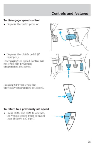
When speed control is on and you are driving uphill, your vehicle speed
may drop considerably, especially if you are carrying a heavy load.
If vehicle speed drops more than 16 km/h (10 mph), the speed control
will cancel automatically. Resume speed with accelerator pedal.
If speed control cancels after climbing the hill, reset speed by pressing
and holding the SET ACCEL button (to resume speeds over 50 km/h [30
mph]).
Automatic transaxles may shift frequently while driving up steep grades.
Eliminate frequent shifting by shifting out of (Overdrive) into D
(Drive).
Driving on snow and ice
An 4x4 vehicle has advantages over 2WD vehicles in snow and ice but
can skid like any other vehicle.
Avoid sudden applications of power and quick changes of direction on
snow and ice. Apply the accelerator slowly and steadily when starting
from a full stop.
When braking, apply the brakes as you normally would. In order to allow
the anti-lock brake system (ABS) to operate properly, keep steady
pressure on the brake pedal.
154](https://image.slidesharecdn.com/01escape-140831143452-phpapp01/85/01-escape-154-320.jpg)

![Maintenance and care
specification ESE-M97B44–A. Use of such coolant may harm the engine
and cooling system components.
Ford Motor Company does NOT recommend the use of recycled engine
coolant in vehicles originally equipped with Motorcraft Premium Gold
Engine Coolant since a Ford-approved recycling process is not yet
available.
Used engine coolant should be disposed of in an appropriate
manner. Follow your community’s regulations and standards for recycling
and disposing of automotive fluids.
Coolant refill capacity
To find out how much fluid your vehicle’s cooling system can hold, refer
to Refill capacities in the Capacities and specifications chapter.
Fill your engine coolant reservoir as outlined in Adding engine coolant
in this chapter.
Severe climates
If you drive in extremely cold climates (less than –36° C [–34° F]):
² It may be necessary to increase the coolant concentration
above 50%.
² NEVER increase the coolant concentration above 60%.
² Increased engine coolant concentrations above 60% will
decrease the overheat protection characteristics of the engine
coolant and may cause engine damage.
² Refer to the chart on the coolant container to ensure the
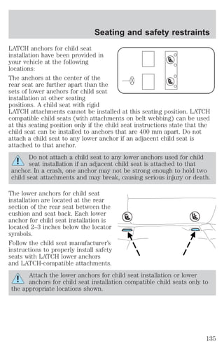
coolant concentration in your vehicle will provide adequate
freeze protection at the temperatures in which you drive in the
winter months.
If you drive in extremely hot climates:
² It is still necessary to maintain the coolant concentration
above 40%.
² NEVER decrease the coolant concentration below 40%.
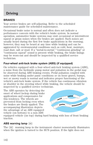
² Decreased engine coolant concentrations below 40% will
decrease the corrosion protection characteristics of the engine
coolant and may cause engine damage.
212](https://image.slidesharecdn.com/01escape-140831143452-phpapp01/85/01-escape-212-320.jpg)
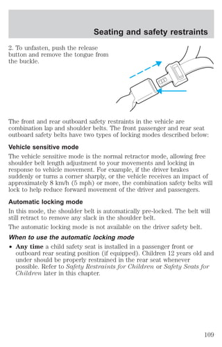
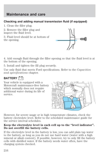
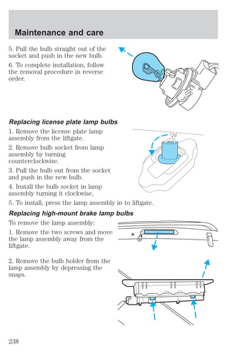
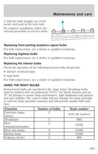
![Maintenance and care
5. If the fluid is low, add fluid in small amounts, continuously checking
the level until it reaches the range between the MIN and MAX lines. Be
sure to put the cap back on the reservoir.
TRANSMISSION FLUID
Checking automatic transmission fluid (if equipped)
Refer to your scheduled maintenance guide for scheduled intervals for
fluid checks and changes. Your transaxle does not consume fluid.
However, the fluid level should be checked if the transaxle is not working
properly, i.e., if the transaxle slips or shifts slowly or if you notice some
sign of fluid leakage.
Automatic transmission fluid expands when warmed. To obtain an
accurate fluid check, drive the vehicle until it is warmed up
(approximately 30 km [20 miles]). If your vehicle has been
operated for an extended period at high speeds, in city traffic
during hot weather or pulling a trailer, the vehicle should be
turned off for about 30 minutes to allow fluid to cool before
checking.
1. Drive the vehicle 30 km (20 miles) or until it reaches normal operating
temperature.
2. Park the vehicle on a level surface and engage the parking brake.
3. With the parking brake engaged and your foot on the brake pedal,
start the engine and move the gearshift lever through all of the gear
ranges. Allow sufficient time for each gear to engage.
4. Latch the gearshift lever in P (Park) and leave the engine running.
5. Remove the dipstick, wiping it clean with a clean, dry lint free rag. If
necessary, refer to Identifying components in the engine compartment
in this chapter for the location of the dipstick.
6. Install the dipstick making sure it is fully seated in the filler tube.
7. Remove the dipstick and inspect the fluid level. The fluid should be in
the crosshatch zone for normal operating temperature.
Low fluid level
Do not drive the vehicle if the fluid
level is at the bottom of the dipstick
and the outside temperatures are
above 10°C (50°F).
214](https://image.slidesharecdn.com/01escape-140831143452-phpapp01/85/01-escape-214-320.jpg)
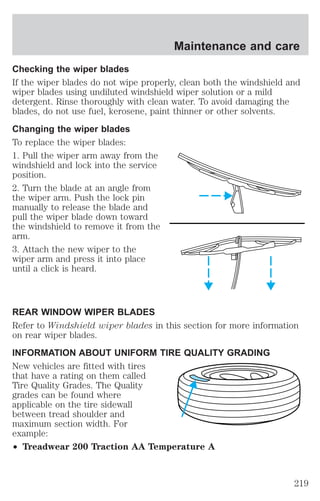
![Maintenance and care
Correct fluid level
The transmission fluid should be checked at normal operating
temperatures 66°C-77°C (150°F-170°F) on a level surface. The normal
operating temperature can be reached after approximately 30 km (20
miles) of driving.
The transmission fluid should be in
the crosshatch zone if at normal
operating temperature (66°C-77°C
[150°F-170°F]).
High fluid level
Fluid levels above the crosshatch
zone may result in transaxle failure.
An overfill condition of transmission
fluid may cause shift and/or
engagement concerns and/or
possible damage.
High fluid levels can be caused by an overheating condition.
Adjusting automatic transmission fluid levels
Before adding any fluid, make sure the correct type is used. The type of
fluid used is normally indicated on the dipstick and also in the
Lubricant specifications section in the Capacities and specifications
chapter.
Use of a non-approved automatic transmission fluid may cause
internal transaxle component damage.
If necessary, add fluid in 250 mL (1/2 pint) increments through the filler
tube until the level is correct.
If an overfill occurs, excess fluid
should be removed by a qualified
technician.
An overfill condition of
transmission fluid may cause
shift and/or engagement concerns and/or possible damage.
215](https://image.slidesharecdn.com/01escape-140831143452-phpapp01/85/01-escape-215-320.jpg)
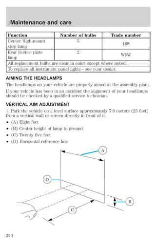
![Maintenance and care
² Idling for long periods of time (greater than one minute) may waste
fuel.
² Anticipate stopping; slowing down may eliminate the need to stop.
² Sudden or hard accelerations may reduce fuel economy.
² Slow down gradually.
² Driving at reasonable speeds (traveling at 88 km/h [55 mph] uses 15%
less fuel than traveling at 105 km/h [65 mph]).
² Revving the engine before turning it off may reduce fuel economy.
² Using the air conditioner or defroster may reduce fuel economy.
² You may want to turn off the speed control in hilly terrain if
unnecessary shifting between third and fourth gear occurs.
Unnecessary shifting of this type could result in reduced fuel
economy.
² Warming up a vehicle on cold mornings is not required and may
reduce fuel economy.
² Resting your foot on the brake pedal while driving may reduce fuel
economy.
² Combine errands and minimize stop-and-go driving.
Maintenance
² Keep tires properly inflated and use only recommended size.
² Operating a vehicle with the wheels out of alignment will reduce fuel
economy.
² Perform all regularly scheduled maintenance items. Follow the
recommended maintenance schedule and owner maintenance checks
found in your vehicle scheduled maintenance guide.
Conditions
² Heavily loading a vehicle or towing a trailer may reduce fuel economy
at any speed.
² Carrying unnecessary weight may reduce fuel economy (approximately
0.4 km/L [1 mpg] is lost for every 180 kg [400 lb] of weight carried).
² Adding certain accessories to your vehicle (for example bug
deflectors, rollbars/light bars, running boards, ski/luggage racks) may
reduce fuel economy.
² Using fuel blended with alcohol may lower fuel economy.
232](https://image.slidesharecdn.com/01escape-140831143452-phpapp01/85/01-escape-232-320.jpg)
![Customer assistance
² The Federal Communications Commission (FCC) and Canadian Radio
Telecommunications Commission (CRTC) regulate the use of mobile
communications systems - such as two-way radios, telephones and
theft alarms - that are equipped with radio transmitters. Any such
equipment installed in your vehicle should comply with FCC or CRTC
regulations and should be installed only by a qualified service
technician.
² Mobile communications systems may harm the operation of your
vehicle, particularly if they are not properly designed for automotive
use or are not properly installed. When operated, such systems may
cause the engine to stumble or stall or cause the transmission to be
damaged or operate improperly. In addition, such systems may be
damaged or their performance may be affected by operating your
vehicle. If you intend on fitting a mobile radio such as a citizens band
radio (CB), please refer to your local dealer for Ford recommended
installation guidelines. Ask you dealer to reference the “Ford Mobile
Radio Installation Guidelines.” (Citizens band [CB] transceivers, garage
door openers and other transmitters with outputs of five watts or less
will not ordinarily affect your vehicle’s operation.)
² Ford cannot assume responsibility for any adverse effects or damage
that may result from the use of such equipment.
ORDERING ADDITIONAL OWNER’S LITERATURE
To order the publications in this portfolio, contact Helm, Incorporated at:
HELM, INCORPORATED
P.O. Box 07150
Detroit, Michigan 48207
Or call:
For a free publication catalog, order toll free: 1-800-782-4356
Monday-Friday 8:00 a.m. - 6:00 p.m. EST
(Items in this catalog may be purchased by credit card holders only.)
Obtaining a French owner’s guide
French Owner’s Guides can be obtained from your dealer or by writing to
Ford Motor Company of Canada, Limited, Service Publications, P.O. Box
1580, Station B, Mississauga, Ontario L4Y 4G3.
267](https://image.slidesharecdn.com/01escape-140831143452-phpapp01/85/01-escape-267-320.jpg)