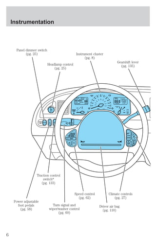
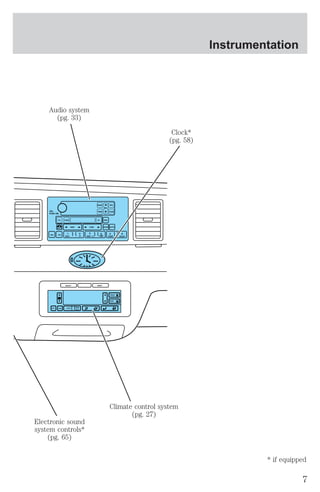
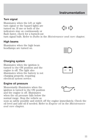
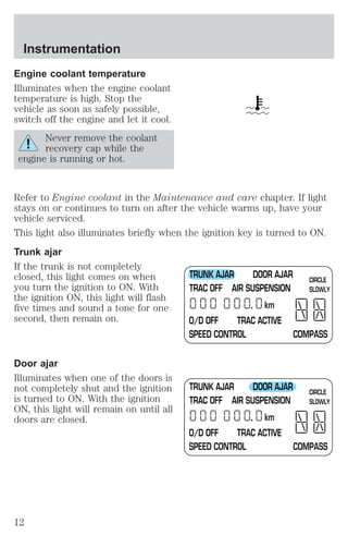
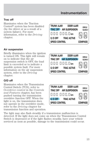
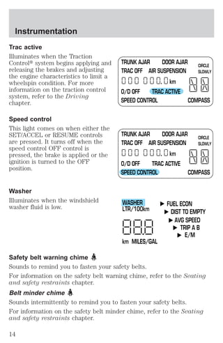
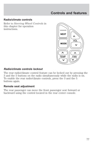
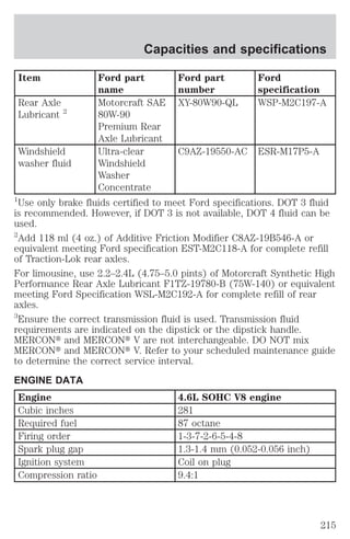
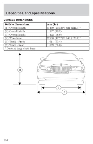
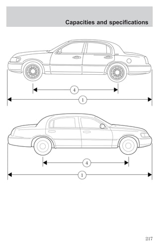
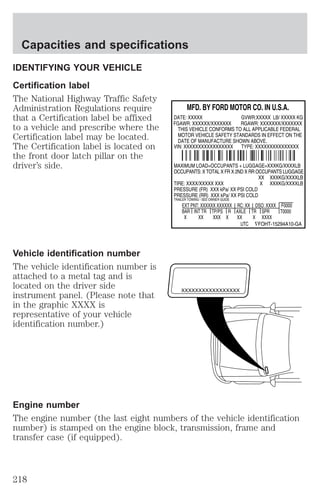
This document provides an overview of instrumentation, controls, and features for a vehicle. It includes descriptions and pictures to explain the purpose and function of various dashboard controls, indicators, and warning lights. Safety information is also provided to explain important alerts and how to respond. The document is an owner's manual intended to help operators understand and properly use all aspects of their vehicle.
![Instrumentation
3. Press and hold the CALIBRATION
BUTTON for 2 to 4 seconds until
CIRCLE SLOWLY is displayed on the
message center.
4. Release pressure from the button.
5. Slowly drive the vehicle in a
circle (less than 5 km/h [3 mph])
until the CIRCLE SLOWLY indicator
turns off. This will take up to five circles to complete calibration.
6. The compass is now calibrated.
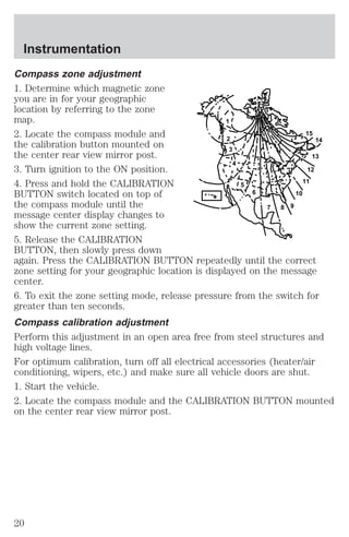
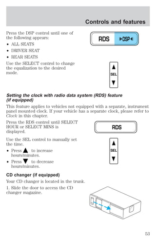
Message center functions
Fuel econ (Average fuel economy)
Select this function to display your
average fuel economy in
liters/100 km or miles/gallon.
If you calculate your average fuel
economy by dividing liters of fuel
used by 100 kilometers traveled
(miles traveled by gallons used),
your figure may be different than
displayed for the following reasons:
² your vehicle was not perfectly level during fill-up
² differences in the automatic shut-off points on the fuel pumps at
service stations
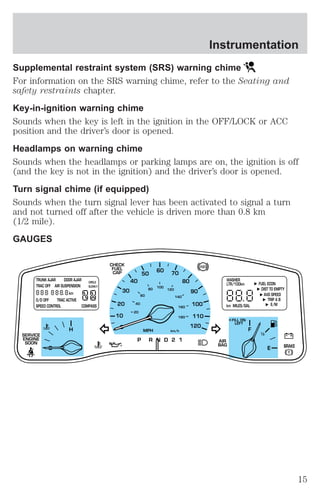
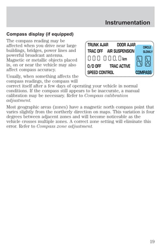
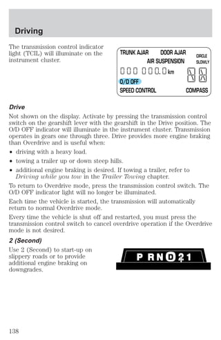
TR UNK AJAR DOOR AJAR
TRAC OFF AIR SUSPENSION
km
CIRCLE
SLOWLY
O/D OFF TRAC ACTIVE
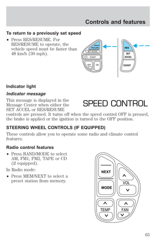
SPEED CONTROL COMPASS
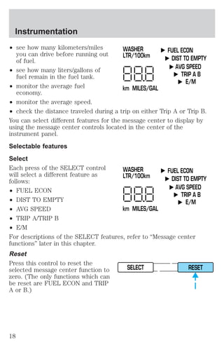
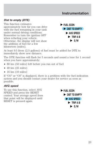
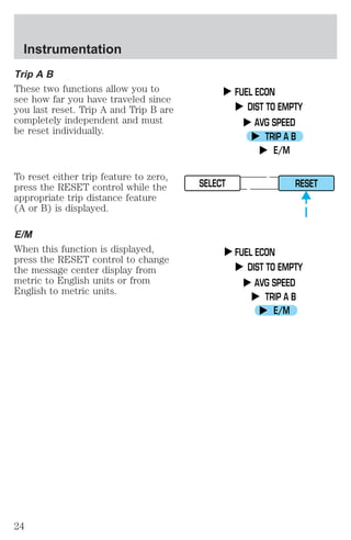
FUEL ECON
DIST TO EMPTY
AVG SPEED
TRIP A B
E/M
² variations in top-off procedure from one fill-up to another
² rounding of the displayed values to the nearest 0.1 liter (gallon)
Checking your highway fuel economy using the electronic
message center display
The following procedure will allow you to accurately monitor your actual
highway fuel economy. Since this procedure requires the vehicle speed
control system to be set to highway speeds, it must be run only on
suitable roadways where long distance speed control can be safely
maintained.
21](https://image.slidesharecdn.com/01towncar-140831143532-phpapp02/85/01-town-car-21-320.jpg)
![Instrumentation
You may notice gradual improvement in fuel economy over the course of
your vehicle’s break-in period (approximately 1 600 kilometers
[1 000 miles]).
1. Set the speed control. Refer to Speed control in the Controls and
features chapter.
2. Select FUEL ECON
3. Press the RESET control to clear
the system memory.
² Actual highway fuel economy is
FUEL ECON
DIST TO EMPTY
AVG SPEED
TRIP A B
E/M
SELECT RESET
now displayed. This current
average measure will change as
the speed control system changes the engine speed to maintain a
constant vehicle speed. This is most noticeable in hilly environments.
4. Drive the vehicle at least 8 km (5 miles) with the speed control
system engaged to display a stabilized average.
5. Record the highway fuel economy for future reference.
It is important to press the RESET control after setting the speed
control to get accurate highway fuel economy readings.
22](https://image.slidesharecdn.com/01towncar-140831143532-phpapp02/85/01-town-car-22-320.jpg)
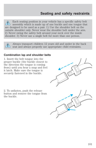
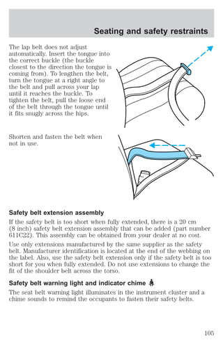
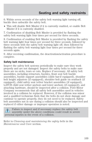
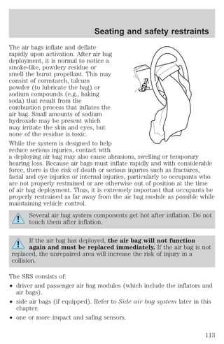
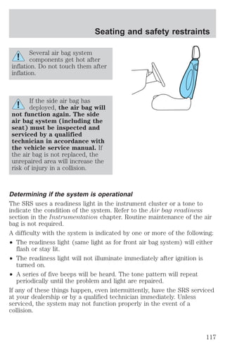
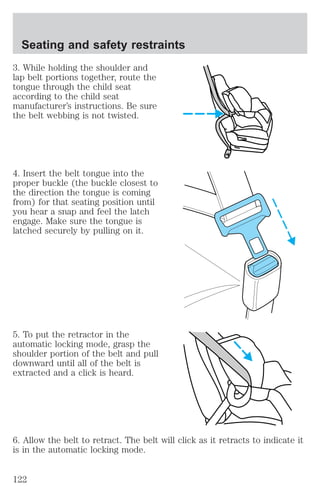
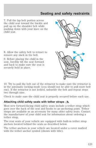
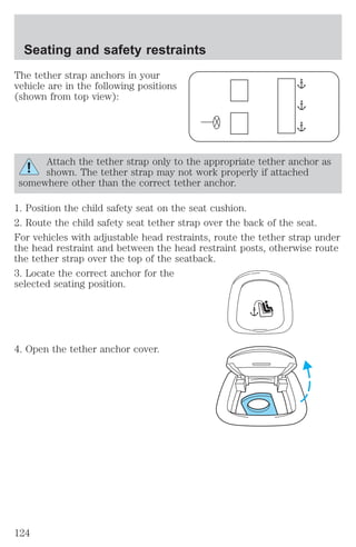
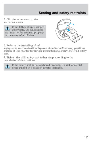
![Seating and safety restraints
Disposal of air bags and air bag equipped vehicles
(including pretensioners)
For disposal of air bags or air bag equipped vehicles, see your local
dealership or qualified technician. Air bags MUST BE disposed of by
qualified personnel.
SAFETY RESTRAINTS FOR CHILDREN
See the following sections for directions on how to properly use safety
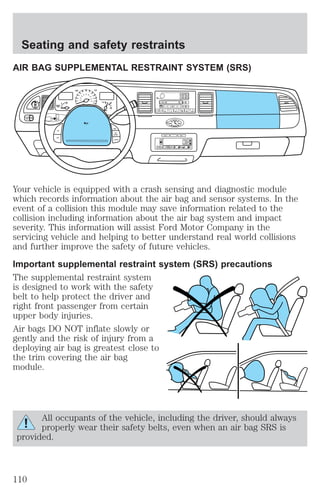
restraints for children. Also see Air Bag Supplemental Restraint
System (SRS) in this chapter for special instructions about using air
bags.
Important child restraint precautions
You are required by law to use safety restraints for children in the U.S.
and Canada. If small children ride in your vehicle (generally children who
are four years old or younger and who weigh 18 kg [40 lbs] or less), you
must put them in safety seats made especially for children. Check your
local and state or provincial laws for specific requirements regarding the
safety of children in your vehicle.
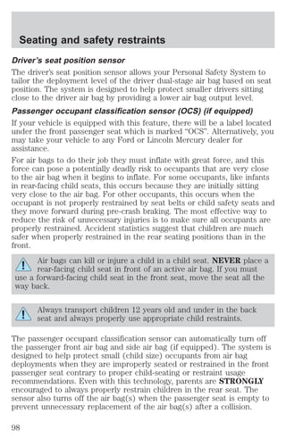
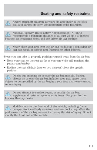
Never let a passenger hold a child on his or her lap while the
vehicle is moving. The passenger cannot protect the child from
injury in a collision.
Always follow the instructions and warnings that come with any infant or
child restraint you might use.
When possible, always place children under age 12 in the rear seat of
your vehicle. Accident statistics suggest that children are safer when
properly restrained in the rear seating positions than in the front seating
position.
Children and safety belts
If the child is the proper size, restrain the child in a safety seat.
Children who are too large for child safety seats (as specified by your
child safety seat manufacturer) should always wear safety belts.
Follow all the important safety restraint and air bag precautions that
apply to adult passengers in your vehicle.
118](https://image.slidesharecdn.com/01towncar-140831143532-phpapp02/85/01-town-car-118-320.jpg)

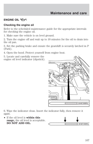
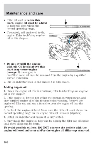
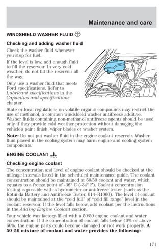
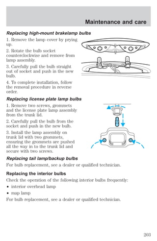
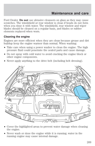
![Maintenance and care
If you have to add more than 1.0 liter (1.0 quart) of engine coolant per
month, have your dealer check the engine cooling system. Your cooling
system may have a leak. Operating an engine with a low level of coolant
can result in engine overheating and possible engine damage.
Recycled engine coolant
Ford Motor Company recommends the use of a recycled engine coolant
produced by Ford-approved processes in vehicles originally equipped
with Motorcraft Premium Engine Coolant (green-colored). However, not
all coolant recycling processes produce coolant that meets Ford
specification ESE-M97B44–A. Use of such coolant may harm the engine
and cooling system components.
Ford Motor Company does NOT recommend the use of recycled engine
coolant in vehicles originally equipped with Motorcraft Premium Gold
Engine Coolant since a Ford-approved recycling process is not yet
available.
Used engine coolant should be disposed of in an appropriate
manner. Follow your community’s regulations and standards for recycling
and disposing of automotive fluids.
Coolant refill capacity
To find out how much fluid your vehicle’s cooling system can hold, refer
to Refill capacities in the Capacities and specifications chapter.
Fill your engine coolant reservoir as outlined in Adding engine coolant
in this chapter.
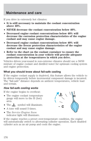
Severe climates
If you drive in extremely cold climates (less than –36° C [–34° F]):
² It may be necessary to increase the coolant concentration
above 50%.
² NEVER increase the coolant concentration above 60%.
² Increased engine coolant concentrations above 60% will
decrease the overheat protection characteristics of the engine
coolant and may cause engine damage.
² Refer to the chart on the coolant container to ensure the
coolant concentration in your vehicle will provide adequate
freeze protection at the temperatures in which you drive in the
winter months.
175](https://image.slidesharecdn.com/01towncar-140831143532-phpapp02/85/01-town-car-175-320.jpg)
![Maintenance and care
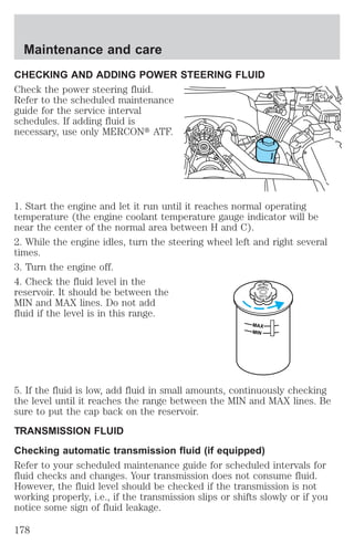
Automatic transmission fluid expands when warmed. To obtain an
accurate fluid check, drive the vehicle until it is at normal operating
temperature (approximately 30 km [20 miles]). If your vehicle has been
operated for an extended period at high speeds, in city traffic during hot
weather or pulling a trailer, the vehicle should be turned off for about 30
minutes to allow fluid to cool before checking.
1. Drive the vehicle 30 km (20 miles) or until it reaches normal operating
temperature.
2. Park the vehicle on a level surface and engage the parking brake.
3. With the parking brake engaged and your foot on the brake pedal,
start the engine and move the gearshift lever through all of the gear
ranges. Allow sufficient time for each gear to engage.
4. Latch the gearshift lever in P (Park) and leave the engine running.
5. Remove the dipstick, wiping it clean with a clean, dry lint free rag. If
necessary, refer to Identifying components in the engine compartment
in this chapter for the location of the dipstick.
6. Install the dipstick making sure it is fully seated in the filler tube.
7. Remove the dipstick and inspect the fluid level. The fluid should be in
the designated area for normal operating temperature or ambient
temperature.
Low fluid level
Do not drive the vehicle if the fluid
level is at the bottom of the dipstick
and the ambient temperature is
above 10°C (50°F).
DON’T ADD
Correct fluid level
The transmission fluid should be checked at normal operating
temperature 66°C-77°C (150°F-170°F) on a level surface. The normal
operating temperature can be reached after approximately 30 km
(20 miles) of driving.
179](https://image.slidesharecdn.com/01towncar-140831143532-phpapp02/85/01-town-car-179-320.jpg)
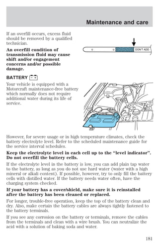
![You can check the fluid without driving if the ambient temperature is
above 10°C (50°F). However, if fluid is added at this time, an overfill
condition could result when the vehicle reaches normal operating
temperature.
The transmission fluid should be in
this range if at normal operating
temperature (66°C-77°C
[150°F-170°F]).
The transmission fluid should be in
this range if at ambient temperature
(10°C-35°C [50°F-95°F]).
DON’T ADD
DON’T ADD
High fluid level
Fluid levels above the safe range
may result in transmission failure.
An overfill condition of transmission
fluid may cause shift and/or
DON’T ADD
engagement concerns and/or
possible damage.
High fluid levels can be caused by
an overheating condition.
Adjusting automatic transmission fluid levels
Before adding any fluid, make sure the correct type is used. The type of
fluid used is normally indicated on the dipstick and also in the
Lubricant specifications section in the Capacities and specifications
chapter.
Use of a non-approved automatic transmission fluid may cause
internal transmission component damage.
If necessary, add fluid in 250 ml (1/2 pint) increments through the filler
tube until the level is correct.
Maintenance and care
180](https://image.slidesharecdn.com/01towncar-140831143532-phpapp02/85/01-town-car-180-320.jpg)
![Maintenance and care
² Idling for long periods of time (greater than one minute) may waste
fuel.
² Anticipate stopping; slowing down may eliminate the need to stop.
² Sudden or hard accelerations may reduce fuel economy.
² Slow down gradually.
² Driving at reasonable speeds (traveling at 88 km/h [55 mph] uses 15%
less fuel than traveling at 105 km/h [65 mph]).
² Revving the engine before turning it off may reduce fuel economy.
² Using the air conditioner or defroster may reduce fuel economy.
² You may want to turn off the speed control in hilly terrain if
unnecessary shifting between third and fourth gear occurs.
Unnecessary shifting of this type could result in reduced fuel
economy.
² Warming up a vehicle on cold mornings is not required and may
reduce fuel economy.
² Resting your foot on the brake pedal while driving may reduce fuel
economy.
² Combine errands and minimize stop-and-go driving.
Maintenance
² Keep tires properly inflated and use only recommended size.
² Operating a vehicle with the wheels out of alignment will reduce fuel
economy.
² Perform all regularly scheduled maintenance items. Follow the
recommended maintenance schedule and owner maintenance checks
found in your vehicle scheduled maintenance guide.
Conditions
² Heavily loading a vehicle or towing a trailer may reduce fuel economy
at any speed.
² Carrying unnecessary weight may reduce fuel economy (approximately
0.4 km/L [1 mpg] is lost for every 180 kg [400 lb] of weight carried).
² Adding certain accessories to your vehicle (for example bug
deflectors, rollbars/light bars, running boards, ski/luggage racks) may
reduce fuel economy.
² Using fuel blended with alcohol may lower fuel economy.
196](https://image.slidesharecdn.com/01towncar-140831143532-phpapp02/85/01-town-car-196-320.jpg)
![Customer assistance
the front or rear axle (GVWR or GAWR as indicated on the Safety
compliance certification label). Consult your dealer for specific weight
information.
² The Federal Communications Commission (FCC) and Canadian Radio
Telecommunications Commission (CRTC) regulate the use of mobile
communications systems - such as two-way radios, telephones and
theft alarms - that are equipped with radio transmitters. Any such
equipment installed in your vehicle should comply with FCC or CRTC
regulations and should be installed only by a qualified service
technician.
² Mobile communications systems may harm the operation of your
vehicle, particularly if they are not properly designed for automotive
use or are not properly installed. When operated, such systems may
cause the engine to stumble or stall or cause the transmission to be
damaged or operate improperly. In addition, such systems may be
damaged or their performance may be affected by operating your
vehicle. (Citizens band [CB] transceivers, garage door openers and
other transmitters with outputs of five watts or less will not ordinarily
affect your vehicle’s operation.)
² Ford cannot assume responsibility for any adverse effects or damage
that may result from the use of such equipment.
ORDERING ADDITIONAL OWNER’S LITERATURE
To order the publications in this portfolio, contact Helm, Incorporated at:
HELM, INCORPORATED
P.O. Box 07150
Detroit, Michigan 48207
Or call:
For a free publication catalog, order toll free: 1-800-782-4356
Monday-Friday 8:00 a.m. - 6:00 p.m. EST
(Items in this catalog may be purchased by credit card holders only.)
Obtaining a French owner’s guide
French Owner’s Guides can be obtained from your dealer or by writing to
Ford Motor Company of Canada, Limited, Service Publications, P.O. Box
1580, Station B, Mississauga, Ontario L4Y 4G3.
228](https://image.slidesharecdn.com/01towncar-140831143532-phpapp02/85/01-town-car-228-320.jpg)