JSC "GTL" is developing a technology to directly synthesize alcohols from natural gas or associated gas, then process the alcohols into high octane gasoline and diesel fuel. The company has invested over 2 billion rubles in R&D. It is currently building a pilot plant with 1,000 ton/year methanol capacity in Bratsk. The plant is scheduled to launch in May 2014 and produce 350-420 tons/year of gasoline. The technology allows for cost effective processing of gas from small, remote, or low pressure fields into liquid fuels.
Methanol most flexible chemical commodities and energy sources produced from convert the feedstock natural gas into a synthesis gas and also by catalytic synthesis of methanol
Episode 3 : Production of Synthesis Gas by Steam Methane ReformingSAJJAD KHUDHUR ABBAS
Episode 3 : Production of Synthesis Gas by Steam Methane Reforming
History of Synthesis Gas
In 1780, Felice Fontana discovered that combustible gas develops if water vapor is passed over carbon at temperatures over 500 °C. This CO and H2 containing gas was called water gas and mainly used for lighting purposes in the19th century.
As of the beginning of the 20th century, H2/CO-mixtures were used for syntheses of hydrocarbons and then, as a consequence, also called synthesis gas.
Haber and Bosch discovered the synthesis of ammonia from H2 and N2 in 1910 and the first industrial ammonia synthesis plant was commissioned in 1913.
The production of liquid hydrocarbons and oxygenates from syngas conversion over iron catalysts was discovered in 1923 by Fischer and Tropsch.
Much of the syngas conversion processes were being developed in Germany during the first and second world wars at a time when natural resources were becoming scare and alternative routes for hydrogen production, ammonia synthesis, and transportation fuels were a necessity.
In 1943/44, this was applied for large-scale production of artificial fuels from synthesis gas in Germany.
Thermodynamic modeling and experimental study of rice husk pyrolysiseSAT Journals
Abstract Pyrolysis of agricultural waste is a promising route for waste to energy generation. Rice husk is a type of agro-waste that is available in plenty in India. It can be used as feed for pyrolysis to produce different products such as (solid) coke and silica, (liquid) tar and other organics and syngas. HSC Chemistry computer aided code for thermodynamic modeling was used to predict the products of rice-husk pyrolysis in this research study. The pyrolysis of rice husk was carried out between 100-1200°C in the pressure range of 1 – 15 bar. The pyrolysis products predicted by HSC calculations were mainly solid coke, gases like H2, CO2, CO, CH4, with small quantity of aromatic compounds like C6H6, C7H8, C8H10 (ethyl benzene), C8H10 (xylenes) and C6H5 –OH. An experimental study for product validation was also done and the results are presented. Keywords: Pyrolysis, syngas, HSC Chemistry, aromatic compounds.
Gasification process for generating producer gas by updraft, downdraft etc. and advantage and disadvantages of gasifier and application of producer gas for generating electricity or motive power for running the engine.
In this project we basically studied scope of this project, its feasibility and market assessment, raw material availability, different routes to produce Syngas and their comparison, process selection and its complete description, its P&ID, and environmental consideration.
SYNGAS PRODUCTION BY DRY REFORMING OF METHANE OVER CO-PRECIPITATED CATALYSTSIAEME Publication
The syngas manufacturing from the reforming of methane with carbon dioxide is tempting because of output in terms of extra pure synthesis gas and lower H2 to CO ratio than other synthesis gas production methods like either partial oxidation or steam reforming. For production of long-chain hydrocarbons though the Fischer-Tropsch synthesis, lower H2 to CO ratio is required and important, as it is a most likely feedstock. In recent decades, CO2 utilization has become more and more important in view of the emergent global warming phenomenon. On the environmental point of view, methane reforming is tantalizing due to the reduction of carbon dioxide and methane emissions as both are consider as dangerous greenhouse gases. Commercially, as cost effectively, nickel is used for methane reforming reactions due to its availability and lower cost compared to noble metals. Number of catalysts endures rigorous deactivation because of carbon deposition. Mainly carbon formation is because of methane decomposition and CO disproportionate. It is important and required to recognize essential steps of activation and conversion of CH4 and CO2 to design catalysts that minimize deactivation. Effect of promoters on activity and stability were studied in the detail. In order to develop the highly active with minimum coke formation the alkali metal oxides and ceria/zirconia/magnesia promoters were incorporated in the catalysts. The influence of ZrO2, CeO2 and MgO, in the performance of Ni-Al2O3 catalyst, prepare by co-precipitation method was studied in detailed. The XRD, FTIR, and BET and reactivity test for different promoted and unprompted catalyst was carried out.
Production of Syngas from biomass and its purificationAwais Chaudhary
This project includes production of syngas from biomass and its purification. Firstly we discuss feasibility and availability of raw material. Then we have literature survey. A lot of techniques are there to produce syngas, we have discuss process selection. Environmental considerations are also have been discussed. Piping and instrumentation (P&ID) diagrams also have been attached. At the end we've our conclusion and our recommendations.
Bp methanol presentation to China ndrc for methanol as fuels 2006Steve Wittrig
Presentation made to China National Development and Reform Commission at their request by Scott Charpentier and Steve Wittrig on the global experience and guidance to China for methanol as a transport fuel.
In the plant, ammonia is produced from synthesis gas containing hydrogen and nitrogen in the ratio of approximately 3:1. Besides these components, the synthesis gas contains inert gases such as argon and methane to a limited extent. The source of H2 is demineralized water and the hydrocarbons in the natural gas. The source of N2 is the atmospheric air. The source of CO2 is the hydrocarbons in the natural gas feed. Product ammonia and CO2 is sent to urea plant. The present article intended the description of ammonia plant for natural gas based plants and the possible material balance of some section.
In the plant, ammonia is produced from synthesis gas containing hydrogen and nitrogen in the
ratio of approximately 3:1. Besides these components, the synthesis gas contains inert gases such
as argon and methane to a limited extent. The source of H2 is demineralized water and the
hydrocarbons in the natural gas. The source of N2 is the atmospheric air. The source of CO2 is
the hydrocarbons in the natural gas feed. Product ammonia and CO2 is sent to urea plant. The
present article intended the description of ammonia plant for natural gas based plants and the
possible material balance of some section
This is a presentation on the design of plant for producing 20 million standard cubic feet per day (0.555 × 10⁶ standard m3/day) of hydrogen (H2) of at least 95% purity from heavy fuel oil (HFO) with an upstream time of 7680 hours/year applying the process of partial oxidation of the heavy oil feedstock.
GE / Texaco Gasifier Feed to a Lurgi Methanol Plant and its Effect on Methano...Gerard B. Hawkins
GE / Texaco Gasifier Feed to a Lurgi Methanol Plant and its Effect on Methanol Production
CONTENTS
0 Methanol Synthesis Introduction
1 Executive Summary
2 Design Basis
2.1.1 Train I Design Basis
2.1.2 Train II Design Basis
2.1.3 Train III Design Basis
2.2 Design Philosophy
2.2.1 Operability Review
2.3 Assumptions
2.4 Train IV Flowsheet
2.4.1 CO2 Removal
3 Discussion
3.1 Natural Gas Consumption Figures
3.1.1 Base Case
3.1.2 Case 1 – Coal Gasification in Service
3.1.3 Case 2 – Coal Gasification in Service – No CO2 Export
3.2 Methanol Production Figures
3.2.1 Base Case
3.2.2 Case 1 – Coal Gasification in Service
3.2.3 Case 2 – Coal Gasification in Service – No CO2 Export
3.3 85% Natural Gas Availability
3.4 100% Natural Gas Availability
3.5 CO2 Emissions
3.5.1 Base Case
3.5.2 Case 1 – Coal Gasification in Service
3.5.3 Case 2 – Coal Gasification in Service – No CO2 Export
3.6 Specific Consumption Figures
3.6.1 Base Case
3.6.2 Case 1 – Coal Gasification and CO2 Import
3.6.3 Case 2 – Coal Gasification and No CO2 Import
3.7 Train IV Synthesis Gas Composition
4 Further Work
5 Conclusion
APPENDIX
Important Stream Data – Material Balance Stream Data
Texaco Gasifier with HP Steam Raising Boiler
CHARACTERISTICS OF COAL
Material Balance Considerations
Exhaust Gas Recirculation is an effective method for NOx control. The exhaust gases mainly consist of carbon dioxide, nitrogen, etc. and the mixture has higher specific heat compared to atmospheric air. Re-circulated exhaust gas displaces fresh air entering the combustion chamber with carbon dioxide and water vapor present in engine exhaust. As a consequence of this air displacement, lower amount of oxygen in the intake mixture is available for combustion. Reduced oxygen available for combustion lowers the effective air–fuel ratio. This effective reduction in air–fuel ratio affects exhaust emissions
A minor presentation report based on the development of electrolyzer for hydrogen production.
And burning the produced hydrogen along with petrol air mixture or charge in SI Engine.
Explaining the major changes obtained in the fuel emission as well the performance of vehicle
Технология Консорциума GTL для ОАО «ГМК «Норильский никель»gtl-rus_com
Технология Консорциума GTL предложенная ОАО «ГМК «Норильский никель» в рамках международного тендера для выполнения работ по внедрению новейших мировых достижений по утилизации диоксида серы на Медном и Надеждинском металлургическом заводах (МЗ и НМЗ).
New Tax Regime User Guide Flexi Plan Revised (1).pptx
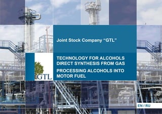
TECHNOLOGY FOR ALCOHOLS DIRECT SYNTHESIS FROM GAS. PROCESSING ALCOHOLS INTO MOTOR FUEL
1.
2. COMPANY INITIATING PROJECT REFERENCE
Full name of the company:
Legal address:
Location address:
Main state registration number:
Main activity:
Taxpayer identification number:
Management:
Shareholder's capital:
IPO:
Joint Stock Company “GTL”
125047, Gasheka Street 8-10, build. 8, Moscow
117246, Nauchniy driveway 8, build. 1, Moscow
1027700525181
engineering and technical activity
7706211944
Kadyrov Rafis Faizovich, President of the Company
519 200 000 rubles
February 2013, Moscow Central Stock Exchange
JSC “GTL” CURRENT CAPITAL STRUCTURE
Registered capital
Fixed assets:
— intangible assets
— research and developments results
Current assets:
— recurring operations
519 200 000 rubles
27.04 billion rubles, including:
24.9 billion rubles
2.14 billion rubles
1.64 billion rubles, including
1.54 billion rubles
3. JSC “GTL” BRIEF REFERENCE
JSC “GTL” was founded in 2000 in order to realize a project of extinguishing flares
and refining natural gas into high-octane engine fuels (petrol and diesel fuel)
avoiding the stage of synthesis gas in the technological process. To fulfill this task
the company has worked out the technology for direct synthesis of alcohols with
their further processing into motor fuel.
The technology is unique due to its high profitability, possibility of refining gas
containing any components with isolating end-product (high-octane petrol, diesel
fuel, methanol, ethanol, helium).
JSC ''GTL'' has invested in R&D aimed at creating this technology 2.139 billion
rubles by 2013, the project is at the stage of building industrial plant.
At the present moment JSC “GTL” in the frames of agreement with JSC “Rosneft” and “ITERA Oil-and-gas company” Ltd. has
started building the plant with capacity 100 thousand tons per annum in the territory of Bratsk Gas Condensate Field
(Krasnoyarsk Territory). The first stage of the project is planned to be launched in May 2014.
4. PROJECT BRIEF DESCRIPTION
AIM OF THE PROJECT
PRODUCTS
TARGETS OF
THE PROJECT
Creating business structure which will provide processing natural and associated gas on the
base of low-tonnage automated unitized GTL plants
Low-tonnage automated unitized GTL plants. The distribution area for the products of the
project is represented by oil companies
Cost efficient development of small and middle gas fields and gas-condensate fields
Processing associated gas in oil fields
Creating and developing market for low-tonnage automated unitized plants of synthetic
liquid fuels
Recycling associated gas for oil production
Monetisation of gas in remote and low-pressure fields
Monetisation of remote shale gas fields
Processing gas into liquid on sea-based platforms
PROJECT STATUS
Current stage of the project (August 2013)
Planned stage of the project (February 2014)
THE STAGE OF DESIGNING
THE STAGE OF THE FIRST INDUSTRIAL LAUNCH
The technical documentation of the petrol synthesis block
of the plant with capacity 100 thousand tons per annum
(for the gas of Bratsk Gas Condensate Field) is prepared.
The preparation for testing pilot plant of direct alcohols
synthesis (1000 tons of methanol) is being terminated.
The launch of pilot plant of direct alcohols synthesis with
capacity 1000 tons of methanol per year to receive
350-420 tons/year of certified gasoline 95 octane per annum.
5. TECHNOLOGICAL PROCESS BRIEF DESCRIPTION
The raw material which goes to reactor is associated oil gas or natural gas containing methane, ethane, propane, butane and other
components. The process may be realized at pressure from 1.5 to 500 at.
Oxygen for reactor is received from air by the method of electromembrane separation with its further special preparation to
facilitate the reaction.
The process of alcohols synthesis is implemented with heat liberation. The optimum temperature for this process is 200-270oС.
Chemical reaction of alcohols synthesis:
1. 2CH4+O2=2CH3OH
from 1m3 of methane
→
1.43 kg of methanol is produced
2. 2C2H6+O2=2C2H5OH
from 1m3 of ethane
→
2.05 kg of ethanol are produced
3. 2C3H8+O2=2C3H7OH
from 1m3 of propane
→
2.68 kg of propanol are produced
4. 2C4H10+O2=2C4H9OH
from 1m3 of butane
→
3.30 kg of butanol are produced
The produced alcohols are extracted from gas phase in liquid form and are directed to the block of petrol synthesis. Depending on
the demand of a client, any alcohol from the mixture can be extracted as a separate product. The gas fractions which have not
entered into reaction are directed to the block of extraction of helium and hydrogen. The balance of produced alcohols depends
on the content of initial gas.
The synthesis of petrol is realized in isothermal reactor with stationary level of high-silicon zeolite catalyst. Service life of
catalyst is three years. The flow of raw material is heated to the temperature of 300-350oС. Space velocity of feeding alcohols:
0.5-1.5 h. Alcohols conversion index during the reaction is not less than 90-95%. Output of liquid hydrocarbons: 38-45%.
Maximum temperature of the reaction: 430 oС.
6. TECHNOLOGICAL PROCESS ADVANTAGES
1.
The synthesis of alcohols is realized without intermediate stages.
2.
The process is going at any pressure, there is no need in regulating pressure, the
synthesis may be fulfilled from natural gas at high pressure and from associated
gas where the pressure is not high.
3.
It does not demand compressing equipment.
4.
The process may be exercised in the field conditions of oil and gas production.
It permits to implement the cost-effective development of small and middle gas
fields and gas condensate fields, remote and low-pressure fields, fields of shale
gas, gas at sea-based platforms, also to process associated gas directly at oil fields.
7. PLANT GENERAL TECHNOLOGICAL SCHEME FOR BRATSK GAS CONDENSATE FIELD
Oxygen
38 576 791 m3/year
5400 kW
Reactor of
direct synthesis of
alcohols and
oxo compounds
from natural gas
Nitrogen
for consumers
Natural gas
35 000 000 m3/year
Electrochemical
fuel cell
Residual gases:
hydrogen, helium,
carbon dioxide
Alcohols and
oxo compounds
(table 1.1)
Gaseous hydrogen
1 076 288 m3/year
Membrane apparatus
of producing helium
Block of
petrol synthesis
Hydrogen
Helium
97000 m3/year
Petrol
24 000 tons/year
Blowing-off gases (table 1.2)
Membrane
separator of air
Air
Table 1.1
Alcohols and Oxo Compounds
Item
tons/year
СН3ОН
50 975.0
С2Н3ОН
564.0
С2Н5ОН
2 758.0
С3Н5ОН
304.0
С3Н7ОН
1 813.5
i-С4Н9ОН
966.0
n-С4Н9ОН
319.0
С4Н7ОН -2-trans
54.7
С4Н7ОН -2-cis
50.4
Table 1.2
Blowing-off Gases
Item
tons/year
Н2
59.9
СН4
487.6
СО
87.3
СО2
63.3
С2Н4
358.8
С2Н6
115.8
С3Н6
220.1
С3Н8
876.0
i-С4Н10
557.4
n-С4Н10
250.1
i-С4Н8 + С4Н8-1
541.2
С4Н8-2-trans
42.5
С4Н8-2-cis
39.2
11. CATALYST
Catalyst of receiving petrol from methanol of NKT-1 mark.
Possible supplies: “New catalystic technologies” LLC.
Design: extrudate having diameter 3-4 mm of white or yellowish colour.
Composition:
High-silicon zeolite (% of mass)
Promoting agents (% of mass)
Bonding agent (% of mass)
70.0
5.0
25.0
Portion of weight loss during tempering at 550 °С, % mass, not more than
Degree of crystallinity of zeolite, %, not less than
Containing dust and granulate, % of mass, not more than
Density, in filling layer, kg/m3
Strength index, kg/mm of diameter
Conversion of methanol, %, not less than
Output of liquid hydrocarbons, % of mass of source methanol
Temperature of reaction start, oC
Maximum temperature of reaction, oC
Maximum temperature of reactivation, oC
Process pressure, mPas
Space velocity of feeding methanol, h -1
5.0
100
2.0
550-800 (according to producer's data 700-750)
1.5
95
35 ÷ 38
350-360
430
550
0.7÷1.0
0.8÷1.2
Cycle length of catalyst at space velocity 1 h-1 and degree of conversion of
methanol 95%, hour
>500
Service life of catalyst, year, not less than
3
12. MATERIAL AND PRODUCT BALANCE OF PLANT
Flow name
1
Taken:
Raw materials 98% methanol, including
methanol
Recycle of raw methanol, including
methanol
Total:
Produced:
Blowing-off gases, including
of separator
of column
High octane component of petrol
Hydro- methanolic mixture, including
methanol
Total:
Kg per hour
2
Outlet
Thousand t/year*
3
% of mass for raw materials
4
180
176.5
63.5
62
243.5
1.107
1.085
0.39
0.381
1.497
100.0
98.0
35.27
34.44
135.27
15
8
7
60.5
168
62
243.5
0.092
0.049
0.043
0.372
1.033
0.381
1.497
8.33
4.44
3.89
33.61
93.33
34.44
135.27
* number of working hours is taken of 6150
The reactor produces 105 kg/h of water steam of 18 at of absolute pressure due to heat removal.
It wastes for its own needs 10 kg/h of steam (for heating cube of stabilizer).
13. END PRODUCTS CHARACTERISTICS
Gas
with the minimum temperature of burning not less than
molecular mass
density
containing H2
containing С3 -С4
11 400 kcal/kg
20.9
0.885 kg/mn3
to 32% of volume
to 43% of volume
The complete component composition is mentioned in technical documentation.
High octane component of petrol
Density at 15°С
Molecular mass
Containing paraffin hydrocarbons
Containing olefin hydrocarbons
Containing naphthene hydrocarbons
Containing aromatic hydrocarbons
Octane number (RON), not less than
Octane number (MON), not less than
Pressure of saturated steams of petrol, mm, not more than
Fractional composition:
start of distillation temperature, °С
10%
50%
90%
end of boiling temperature, °С
The complete component composition is mentioned in technical documentation.
755 kg/m3
90
38-42% of mass
6-7% of mass
9-11% of mass
30-35% of mass (containing benzol: 0.05 - 0.1% of mass)
92
84
500
35
55
120
160
205