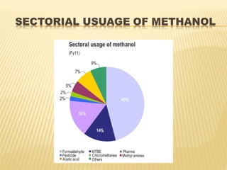
Methanol is the simplest alcohol and can be used as an alternative fuel or chemical feedstock. It is produced via a four step process: feed purification using desulphurization; steam reforming of natural gas over nickel catalysts at high pressures and temperatures; methanol synthesis over copper catalysts in a reactor; and methanol purification through distillation. Methanol production facilities are located globally and the demand for methanol is increasing in countries like India at 7-8% annually.
Calculation of an Ammonia Plant Energy Consumption: Gerard B. Hawkins
Calculation of an Ammonia Plant Energy Consumption:
Case Study: #06023300
Plant Note Book Series: PNBS-0602
CONTENTS
0 SCOPE
1 CALCULATION OF NATURAL GAS PROCESS FEED CONSUMPTION
2 CALCULATION OF NATURAL GAS PROCESS FUEL CONSUMPTION
3 CALCULATION OF NATURAL GAS CONSUMPTION FOR PILOT BURNERS OF FLARES
4 CALCULATION OF DEMIN. WATER FROM DEMIN. UNIT
5 CALCULATION OF DEMIN. WATER TO PACKAGE BOILERS
6 CALCULATION OF MP STEAM EXPORT
7 CALCULATION OF LP STEAM IMPORT
8 DETERMINATION OF ELECTRIC POWER CONSUMPTION
9 DETERMINATION OF THE TOTAL ENERGY CONSUMPTION OF THE AMMONIA PLANT ISBL
10 ADJUSTMENT OF ELECTRIC POWER CONSUMPTION FOR TEST RUN CONDITIONS
11 CALCULATION OF AMMONIA SHARE IN MP STEAM CONSUMPTION IN UTILITIES
12 CALCULATION OF AMMONIA SHARE IN ELECTRIC POWER CONSUMPTION IN UTILITIES
13 DETERMINATION OF THE TOTAL ENERGY CONSUMPTION OF THE AMMONIA PLANT OSBL
14 DETERMINATION OF THE TOTAL ENERGY CONSUMPTION OF THE AMMONIA PLANT
DEACTIVATION OF METHANOL SYNTHESIS CATALYSTS
CONTENTS
1 INTRODUCTION
2 THERMAL SINTERING
3 CATALYST POISONING
4 REACTANT INDUCED DEACTIVATION
5 SUMMARY
TABLES
1 DEACTIVATION PROCESSES ON METHANOL SYNTHESIS CATALYSTS
2 MELTING POINT, HUTTIG AND TAMMANN TEMPERATURES OF COPPER, IRON AND NICKEL
3 SINTERING RATE CONSTANTS CALCULATED INLET AND OUTLET SIDE STREAM UNIT FOR VULCAN VSG-M101
4 COMPARISON BETWEEN CALCULATED S∞ AND DISCHARGED MEASUREMENTS ON VULCAN VSG-M101
5 EFFECT OF POSSIBLE CONTAMINANTS AND POISONS ON CU/ZNO/AL2O3 CATALYSTS FOR METHANOL SYNTHESIS
6 GUARD SCREENING TEST RESULTS ON METHANOL MICRO-REACTOR. EFFECT OF DEPOSITED METALS ON METHANOL ACTIVITY
FIGURES
1 THE HΫTTIG AND TAMMANN TEMPERATURES OF THE COMPONENTS OF A SYNTHESIS CATALYST
2 A SCHEMATIC REPRESENTATION OF TWO CATALYST SINTERING MECHANISMS
3 SIDE STREAM DATA FOR VULCAN VSG-M101. INLET TEMPERATURE 242 OC, PRESSURE 1500 PSI, GAS COMPOSITION 6% CO, 9.2% CO2, 66.9% H2, 2.5% N2 AND 15.4% CH4, SPACE VELOCITY 17,778 HR-1. MEAN OUTLET TEMPERATURE 280 OC
4 TEMPERATURE DEPENDENCE OF THE RATE OF SINTERING
5 MECHANISM OF SULFUR RETENTION
6 CORRELATION OF SULFUR CAPACITY WITH TOTAL SURFACE AREA
7 EFFECT OF DEPOSITED (NI+FE) PPM ON METHANOL SYNTHESIS CATALYST ACTIVITY
8 DISCHARGED (FE + NI) DEPOSITION LEVELS ON METHANOL SYNTHESIS PLANT SAMPLES
9 EPMA ANALYSIS OF DISCHARGED LABORATORY SAMPLE OF POISONED VULCAN VSG-M101
10 THE EFFECT OF CO2 ON SYNTHESIS CATALYST DEACTIVATION
REFERENCES
Episode 3 : Production of Synthesis Gas by Steam Methane ReformingSAJJAD KHUDHUR ABBAS
Episode 3 : Production of Synthesis Gas by Steam Methane Reforming
History of Synthesis Gas
In 1780, Felice Fontana discovered that combustible gas develops if water vapor is passed over carbon at temperatures over 500 °C. This CO and H2 containing gas was called water gas and mainly used for lighting purposes in the19th century.
As of the beginning of the 20th century, H2/CO-mixtures were used for syntheses of hydrocarbons and then, as a consequence, also called synthesis gas.
Haber and Bosch discovered the synthesis of ammonia from H2 and N2 in 1910 and the first industrial ammonia synthesis plant was commissioned in 1913.
The production of liquid hydrocarbons and oxygenates from syngas conversion over iron catalysts was discovered in 1923 by Fischer and Tropsch.
Much of the syngas conversion processes were being developed in Germany during the first and second world wars at a time when natural resources were becoming scare and alternative routes for hydrogen production, ammonia synthesis, and transportation fuels were a necessity.
In 1943/44, this was applied for large-scale production of artificial fuels from synthesis gas in Germany.
Purpose
Key to good performance
Problem Areas
Catalysts, heat shields and plant up-rates
Burner Guns
Development of High Intensity Ring Burner
Case Studies
Conclusions
Introduction High temperature shift Catalysts
Low temperature shift catalysts
Catalyst storage, handling, charging and discharging
Health and safety precautions
Reduction and start-up of high temperature shift catalysts
Operation of high temperature shift catalysts
Reduction and start-up of low temperature shift catalysts
Operation of low temperature shift catalysts
Reactor and Catalyst Design
0 INTRODUCTION/PURPOSE
1 SCOPE
2 FIELD OF APPLICATION
3 DEFINITIONS
4 CATALYST DESIGN
4.1 Equivalent Pellet Diameter
4.2 Voidage
4.3 Pellet Density
5 REACTOR DESIGN
6 CATALYST SUPPORT
6.1 Choice of Support
TABLES
1 CATALYST SUPPORT SHAPES
2 SECONDARY REFORMER SPREADSHEET
FIGURES
1 GRAPH OF EFFECTIVENESS v THIELE MODULUS
2 VARIATION OF COSTS WITH CATALYST SIZE
3 VARIATION OF COSTS WITH CATALYST BED VOIDAGE
4 VARIATION OF COSTS WITH VESSEL DIAMETER
This is great Presentation with 3D effects which is all about production of ammonia from natural gas.
I am damn sure you will be getting everything here searching for.
its better to download it and then run in powerpoint 2013.
These slides are developed for a part of the undergraduate course in Petroleum Refinery Engineering. The slides are also helpful for Masters level introductory course.
(HTS) High Temperature Shift Catalyst (VSG-F101) - Comprehensiev OverviewGerard B. Hawkins
The high temperature shift duty introduction and theory
HTS catalyst characteristics
developments over time
Typical HTS operational problems
Improved catalysts
VULCAN Series VSG-F101 Series
Summary
Methanol most flexible chemical commodities and energy sources produced from convert the feedstock natural gas into a synthesis gas and also by catalytic synthesis of methanol
2. Methanol is a new future alternative fuel and it is also widely used
as a raw material for MTBE and other chemicals.
The demand and production of methanol is increased.
Methanol is the simplest alcohol, light, volatile, colourless,
flammable and poisonous and has distinctive odor very similar to,
but, slightly sweeter than, that of ethanol.
Methanol is also known as methyl alcohol, wood alcohol, wood
spirit.
3. The ancient Egyptians used a mixture of substances, including
methanol, which they obtained from the pyrolysis of wood.
Pure methanol, however, was first isolated in 1661 by Robert Boyle,
who called it spirit of box, because he produced it via the distillation
of boxwood.
In 1834, the French chemists Jean-Baptiste Dumas and Eugene
Peligot determined its elemental composition.
This was shortened to methanol in 1892 by the International
Conference on Chemical Nomenclature.
In 1923, the German chemist Matthias Pier, working for
BASF developed a means to convert synthesis gas (a mixture of
carbon monoxide and hydrogen derived from coke and used as the
source of hydrogen in synthetic ammonia production) into methanol.
Pressures 300–1000 atm,
Temperatures of about 400°C.
4. As a fuel in internal combustion engines, flammable as gasoline.
As a solvent and as an antifreeze in pipelines.
As a denaturing agent.
About 40% of methanol is converted to formaldehyde, and from
there into products as diverse as plastics, plywood, paints,
explosives, and permanent press textiles.
In the 1990s, large amounts of methanol were used in the United
States to produce the gasoline additive methyl tert-butyl
ether (MTBE).
Other chemical derivatives of methanol include dimethyl ether,
which has replaced chlorofluorocarbons as the propellant in
aerosol sprays, and acetic acid.
5.
6. The methanol industry spans the entire globe, with production in Asia, North
and South America, Europe, Africa and the Middle East. Worldwide, over 100
methanol plants have a combined production capacity of about 100 million
metric tons (33 billion gallons or 125 billion litres), and each day more than
180,000 tons of methanol is used as a chemical feedstock or as a transportation
fuel (60 million gallons or 225 million litres).
Indian demand for methanol is likely to increase at the rate of 7% to 8% per
annum till 2015. The likely import of methanol in India by 2015 would be 1.4
million metric tonnes per annum.
The current price of methanol is Rs. 26-30/lit
12. Gujarat Narmada Valley Fertilizers Company (GNFC) is the largest
producer of methanol in India with installed capacity of 268,700 TPA.
Deepak Fertilizers & Petrochemicals Corporation is the second
largest methanol producer with installed capacity of 1,00,000 TPA.
Rashtriya Chemicals & Fertilizers (RCF) is the third largest methanol
producer with installed capacity of 72,600 TPA.
Assam Petrochemicals has an installed capacity of 33,000 TPA of
methanol.
Assam Petrochemical is likely to start commercial production from its
new plant in the fourth quarter of 2014. The new methanol plant at
Namrup, Assam in India, will have a production capacity of 165,000
tonne per annum.
13. Short Term Effects
Small amount
• Nausea, headache, abdominal pain, vomiting and visual
disturbances ranging from blurred vision to light sensitivity.
High concentrations
• Irritate mucous membranes, cause headaches, sleepiness,
nausea, confusion, loss of consciousness, digestive and visual
disturbances and death.
•Long Term Effects
•Repeated exposure
• Systemic poisoning
• Brain disorders
• Impaired vision
• Blindness.
14. Small fires
Dry Chemical
CO2
water spray.
Large fire
Water spray
AFFF(R) (Aqueous Film Forming Foam (alcohol resistant)).
Methanol burns with a clean clear flame that is almost
invisible in daylight
15. Chemically Stable
Incompatible with other substances
Strong oxidizers, strong acids, strong bases.
Conditions of Reactivity
Presence of incompatible materials and ignition sources
Hazardous Decomposition Products
Formaldehyde, carbon dioxide and carbon monoxide
16. Anhydrous methanol is non-corrosive except:
Lead
Magnesium
Methanol is non-corrosive except:
lead
Aluminum
Mild steel is the recommended construction material.
Storage
In totally enclosed equipment
Avoid ignition and human contact
Tanks must be grounded and vented and should have
vapor emission controls.
Avoid storage with incompatible materials.
17. Biodegradation / Aquatic Toxicity:
Methanol biodegrades easily in
Water.
Soil.
Methanol in high concentrations (>1%) in fresh or salt water can have short-
term harmful effects on aquatic life within the immediate spill area.
No smoking or open flame in storage.
Ensure proper electrical grounding procedures are in place.
18. An effective spill prevention program will include
Engineering controls
Training and procedure
Spill response planning.
Effective engineering controls include
Overfill alarms,
Containment for tanks, such as
dikes or bunds to contain large spills.
Workers must be trained to handle methanol in a safe manner.
Systems and procedures that protect the employees.
The plant and the environment should be implemented to be prepared in the
event of a spill.
The facility should develop and implement spill response plans.
Regular exercises of the plan will ensure that workers know how to respond
safely and effectively to a release.
19. Methanol is made using the Low Pressure
Methanol Synthesis Process.
The plants production process that can be
divided into four main stages:
Feed Purification.
Reforming.
Methanol Synthesis.
Methanol Purification.
20. NG is compressed to about 45 bar
sulphur removed by desulphurization
Additional steam to achieve 3:1 steam to carbon ratio for reforming.
The total feed stream is then heated in the gas heated reformer preheater.
21. Steam reforming Partial oxidation Autothermal
reforming
Type of process endothermic exothermic neutral
System
complexicity
complex Very simple simple
Outlet Hydrogen
content(dry
basis)
70-80% 35-45% 40-45%
Carbon yield 9%CO
15% CO2
19% CO
1% CO2
3% CO
15% CO2
System
configuration
complex simple complex
22.
23. • There are three main chemical reactions which occur in this process
step :
• Steam reforming CH4 + H2O = CO + 3H2
Shift reaction CO + H2O =
CO2 + H2
• Preheated gas flows from the preheater to the tube side of the
advanced gas heated reformer (AGHR).
• As it passed down through the catalyst (nickel, zinc oxide based on
alumina) the reforming reactions start.
• Reforming reactions continue and the gas leaves 1000°C with less
than 0.5% methane slip.
• The process condensate which condenses out of the reformed gas is
recycled back to the saturator.
• After heat recovery the reformed gas is finally cooled and then
compressed to about 70 barg in the synthesis gas compressor to be
fed as synthesis gas to the synthesis loop.
24. There are two main chemical reactions which occur in this process
step :
CO + 2H2 = CH3OH
CO2+3H2 = CH3OH + H2O
Production of a crude methanol stream which is about 80% methanol
and 20% water, carried out over a catalyst.
Crude methanol is separated from the uncondensed gases and the
gases recirculated back to the converter via the circulator.
This section consists :
Topping column
Refining column
25. Type of Converter Description
Quench Cooled Converter The warm quench is fed to the converter at
100-1500C. Quench reactor converter
requires relatively large catalyst volume
because the temperature profile does not
follow the same path
Adiabatic bed Converter It has a smaller total catalyst volume. Capital
cost is less
Tube cooled Converter Low catalyst volume leading to smaller
converter volume, increased heat recovery as
compared to quench converter