Downloaded 11 times


![3.5. Emissions
During the warranty test in December 1989 detailed
measurements of flue gas components or of noise rate level
have not been carried out. Only the regular 02 and NO,,
measurements have been carried out with the standard equipment
of Kaldin. In a mutual agreement between Lurgi and Kaldin
additional emission measurements have been carried out in a
later stage.
The NOx-emission which was measured by Kaldin during the
Warranty test is about 940 mg/Nm3
at 7 % 02, which is higher
than the requirements which are mentioned in Kaldin's nuisance
act (500 mg/Nm3
). After gaining more experiences concerning the
use of coal residues, and the corresponding level of the NOx-
emission, effective modifications to the CFB have been made in
order to decrease the NOx-emission. After the end of the
program, with the use of only coal as a fuel the NOx-emission
could be decreased to a level below 500 mg/Nm3
, when using a
limited quantity of combustion air. In this case the quality
of the product, concerning the carbon outburn, could not
always be guaranteed.
Other randomly measured components such as C02, CO and S02 and
components measured at dust samples such as the quantity of
dust, Cd, Pb, Zn, Sb, Hg and fluorides, stay far below the
requirements mentioned in the private nuisance act [1].
3.6. Raw materials
3.6.1. Limestone
During the entire phase 2 a fine-grained limestone has been
processed. This limestone arises as a side-product after
crushing and sieving of limestone, which is used for lime
production in conventional lime calcining kilns.
The composition of the fine-grained limestone is shown in
table 4. Most of the data have been provided by the supplier,
only the CaC03 and water content are averages from the analyses
which have been carried out by the Kaldin laboratory.
The grain size of the limestone is between 0 and 3 mm, and in
average (d50) 0.7 to 0.8 mm.
The limestone is not a pure limestone but consists partly of
sand and clay (about 10 to 15 % m/m). The presence of these
components has a positive effect on the transportability of
the limestone in the plant. On the other hand, the free CaO
19](https://image.slidesharecdn.com/calcinacion-190212023124/85/Calcinacion-33-320.jpg)
![4. CALCINING LIMESTONE WITH COAL RESIDUES
4.1. Introduction
On a laboratory scale, several investigators (Wittneben [2]
and Bloem [3]) have found indications that the use of coal
residues as a raw material in sand-lime bricks can have a
positive effect on the green strength of the moulded product
and on the compressive strength of the cured product (taking
into account the only limited amount of parameters studied).
The greatest disadvantage of the use of coal residues in this
application is the discolouration of the sand-lime bricks. In
stead of white this becomes grey, depending on the carbon
content and the amount of coal residues which is used.
In tests on a pilot-plant scale performed by Lurgi in 1985, it
has been shown that the carbon in coal residues could be
sufficiently burned out in a fluidized bed. After burning out
the carbon, the coal residues could be used as a raw material
for the production of sand-lime bricks, because the
discolouration of the product is acceptable.
A study carried out by Ingenieursbureau Dekker in 1985 [4]
showed that the product (a coal residues-lime mixture) is
suitable for the use in sand-lime brick production and it can
result in a higher green strength of the moulded product, a
higher compressive strength of the cured product and a saving
of the amount of free lime which has to be dosed.
During phase no. 3 of the measuring and monitoring program the
above mentioned conclusions have been checked for the product
which was generated by Kaldin and for the sand-lime bricks
which have been produced by De Hazelaar with the use of Kaldin
lime.
In practice it appeared that several technological
disturbances occurred during phase 2 which resulted in a delay
of the time that the first coal residues could be processed.
In stead of 1 July 1989, only on 30 January 1990 the first
coal residues could be used.
The measuring and monitoring program has been prematurely
concluded after the end of phase 3. As a result thereof no
experiences have been gained with the production of lime with
a maximum coal residues input of 12.5 tons per hour. However
during some short periods, for example during a test which was
monitored by TNO in January 1991, the input of coal residues
has been increased to a reach level which was as high as
possible for that time.
26 -](https://image.slidesharecdn.com/calcinacion-190212023124/85/Calcinacion-40-320.jpg)
![4.2. Operation time
During phase 3, except for some periods, a continuous
production has not been realized. In total, during phase 3
3960 hours production has been realized. This implies an
efficiency of the use of the available operation time of 60 %,
Compared to phase 2 this is an improvement of 12 %.
During almost the entire phase 3 the plant has been operated
in a continuous shift system (3 shifts, 5 days a week).
4.3. Global description of the progress
Originally the aim of the measuring and monitoring program was
to increase the coal residues input gradually from 0 to 12.5
tons per hour. During this increase the effect on the process-
conditions, the quality of the product and the quality of the
sand-lime bricks have been monitored.
During the first two months of phase 3 (February and March
1990) an input of about 2 tons coal residues per hour has been
realized during the periods in which the coal residues has
actually been processed. The limestone input during this
period varied between 13 and 17 tons per hour. No disturbances
were directly a result of the use of coal residues. In April
1990 the coal residues input has been increased to 3 - 4 tons
per hour, interchanged with periods during which this input
was less. Also with the use of this quantity of coal residues
no disturbances occurred which could be related to use of coal
residues. During large parts of the months July, August and
September 1990 the coal residues input has been increased to
about 6 tons per hour. Due to problems with the quality of the
sand-lime bricks, at the end of September it has been decided
to decrease the coal residues input back to 3 - 4 tons per
hour. During the last couple of months in 1990 this has been
reduced to about 3 tons per hour. During the entire phase 3 an
average of 2.53 tons of coal residues per production hour has
been processed.
During a short period in January 1991 (several hours), under
the supervision of TNO [5], a test has been carried out with
an input of 8 tons of coal residues per hour and 16 tons of
limestone per hour. This resulted in a product output of 15 to
16 tons per hour, depending on the carbon content of the coal
residues). During this test, stable process-conditions have
been realized. From this test can be concluded that a further
increase of the coal residues input was technologically
- 27](https://image.slidesharecdn.com/calcinacion-190212023124/85/Calcinacion-41-320.jpg)
![The increase of the flue gas temperature, also as a result
of after-burning of the coal residues, lead to a
deformation of the valves in the return pipe between the
first cyclone and the CFB.
Other problems cannot directly be related to the use of only
coal or coal + coal residues as fuel. These problems are
mostly a result of the generation of a large volume of dust
and the nature of this material.
Depending on the type of coal residues, mostly a small amount
of coal is allways needed in order to keep the the process
conditions at a constant level.
4.6. Emissions
4.6.1. NO^-emission
The components which are continuously analyzed in the flue
gasses of Kaldin are N0X and 02. The N0X content is measured
before the chimney at the same spot as the 02 measurement is
performed.
From these data (in ppm) the NOx-emission can be calculated in
mg/Nm3
, according to the unit in which this parameter is
defined in the private nuisance act, with the aid of the
following formulae:
N0X (mg/Nm3
) = N0X (ppm) x 2.05 x
20.94 - 7 % 02
20.94 - % O,
When coal residues are used, a higher N0X content of the flue
gasses is measured than with the use of only fine-grained
coal. The NO^-emissions with coal residues varied between 900
and 2100 mg/Nm3
, compared to 940 mg/Nm3 which was measured
during the warranty test with only coal (see § 3.5).
During a test period in phase 3, continuous measurements have
been made by DHV of the following components: C02, CO, 02, N0X
and S02 [l]. Samples of the dust have been taken every hour.
These samples have been analyzed on the following components:
Cd, Pb, Zn, Hg, Sb and fluorides.
Also the analyses of DHV show a higher NO*-emission (1000 -
1300 mg/Nm3
as an average per hour) than which is allowed
according to the private nuisance act.
Of the 3 samples of dust which have been measured, the amount
of dust of one sample exceeds the limit mentioned in the
31](https://image.slidesharecdn.com/calcinacion-190212023124/85/Calcinacion-45-320.jpg)
![nuisance act. This is mainly caused by a damage of the cloth
filter at the time the dust samples have been taken. In a
later stage, the bags of the cloth filter have been replaced.
The S02-emission stays largely below the limit of 700 mg/Nm3
.
Also the above mentioned components which have been measured
on the dust samples stay largely below the limits mentioned in
the nuisance act.
After the end of phase 3, several tests have been carried out
regarding possible measures which could be taken to reduce the
N0X emission. From these test results it became clear that the
NO* level depended largely on both the total amount of nitrogen
present in the fuel and on the amount of air which is used for
the combustion of the fuel. Following these results,
modifications have been made to the CFB, which have resulted
in a decrease of the NOx-emission.
With the use of only coal as a fuel the NOx-emission can be
decreased to a level below the limit mentioned in the private
nuisance act (N0X < 500 mg/Nm3
), when using a limited quantity
of combustion air and a reduction of the quality of the
product. When more than about 2 tons of coal residues are
processed, additional measures have to be taken to further
reduce the N0X emission to a level below 500 mg/Nm3
. Tests have
shown that this can be achieved up till a coal residue input
of at least 8 tons per hour. The quality of the product
concerning the carbon outburn and calcination ratio can
however not be guaranteed.
4.6.2. Noise emission
In April 1990 acoustic measurements have been carried out by
Cauberg-Huygen concerning the noise emission of Kaldin and of
De Hazelaar and the nuisance that this noise caused to the
near environment of these factories [6]. When these results
are compared with the limits mentioned in the private nuisance
act, it appears that on some locations the noise level exceeds
the limit which is set for the nighttime (40 dB(A) between
11.00 pm and 7.00 am).
Based on these results, at the end of phase 3 modifications
have been made to some components of the installation and
vehicles which have led to a reduction of the noise level,
although new acoustic measurements have not yet been carried
out in order to quantify this reduction of noise rate level.
32](https://image.slidesharecdn.com/calcinacion-190212023124/85/Calcinacion-46-320.jpg)
![means that the fine-grained particles have always acted mainly
as a filler in addition to the fine-grained sand particles.
In practice during a longer period of time a mixture of Dornap
lime and flyash-lime has been used for the production of sand-
lime bricks and elements.
4.9.4. Laboratory tests
With the flyash-lime several laboratory experiments have been
carried out in which the properties of the sand-lime mortars
and sand-lime bricks have been compared with the mortars and
bricks which were produced using Dornap lime [8]. Following,
the most important results will be discussed. For more detail
the reader is referred to [8].
The samples have been produced by mixing the raw materials in
a laboratory mixer and moulding the mortar into cylinder-
shaped samples. Thereafter they are steam-cured in the plant.
The green strength is determined after the moulding of the
samples and the compressive strength after steam-curing. In
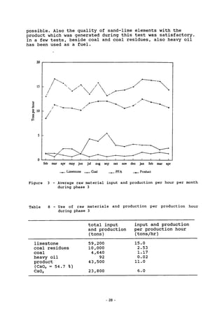
table 12 the results of a comparative study between sand-lime
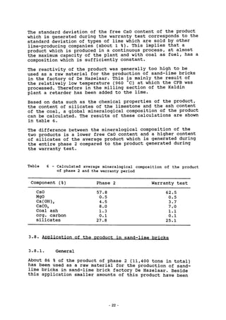
bricks with a flyash-lime (free CaO = 37 %) and with Dornap
lime are shown. From these results it can be concluded that a
larger amount of fine-grained particles (the samples with fly-
ash lime) result in an increase of the apparent density of the
product, together with an increase of green strength and
compressive strength. The water absorption and expansion of
these samples are lower. In order to reach a similar free CaO
content in the mortar, compared to Dornap lime, more than
twice the amount of flyash-lime has to be dosed.
It has however to be noted that question marks have to be
placed with these tests. The apparent density of the samples
is about 150 kg/m3
higher than the apparent density of the
products which are produced in practice by De Hazelaar.
As a result thereof all the data mentioned in table 12 deviate
from the data of products generated in practice. This applies
mainly to the green strength. In practice hardly ever can be
seen that the green strength of a moulded sand-flyash-lime
mortar is higher than of a moulded sand-Dornap lime mortar
(based on an equal free CaO content). Therefor, at the end of
phase 3 the moulding pressure for the preparation of the
samples has been decreased. The result thereof was, in
contradistinction with former times, that a clearer relation
could be seen between the green strength and the product-loss
as a result of fracturing (see section 4.9.5).
39](https://image.slidesharecdn.com/calcinacion-190212023124/85/Calcinacion-53-320.jpg)
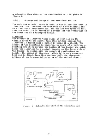
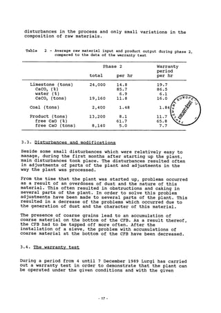
![Table 12 - Properties of sand-lime mortars with Dornap lime and with
flyash-lime, based on laboratory tests
Dornap lime (free CaO = 85 %)
Free CaO % 5.5
Green strength kPa 1.0
Compr. strength MPa 25.3
App. density kg/m3
1825
Water absorption % 13.2
Expansion mm/m 0.7
Flyash-lime (free CaO = 37 %)
Free CaO %
Green strength kPa
Compr. strength MPa
App. density kg/m3
Water absorption %
Expansion mm/m
5.5
1.7
31.9
1870
12.8
0.3
6.5
1.8
33.5
1825
13.1
0.7
6.5
2.2
35.8
1880
12.3
0.6
7.5
2.3
37.3
1840
13.0
0.9
7.5
3.9
42.3
1900
12.3
0.4
8.5
3.7
1860
13.2
1.4
8.5
5.0
43.6
1930
11.6
0.8
9.5
4.9
43.6
1860
13.7
1.4
9.5
6.8
46.7
1925
11.9
0.4
4.9.5. Experiences in practice
During the main part of phase 3 the product-loss of both
bricks and elements was about the same as during phase 2.
A good quality of sand-lime bricks and elements has been
obtained with the use of a flyash-lime or a combination of
Kaldin lime and Filter lime.
However, during some periods with a higher coal residues input
in the Kaldin plant, an increase of product-loss has occurred,
mainly in production of the large elements. Especially the
larger elements are very sensitive for fracturing just after
the moulding of the element and for pressure cracks during
steam-curing. It has to be noted that the increase of product-
loss is probably not only caused by the increase of the coal
residues input in the Kaldin plant. In a latter stage, after
the end of the measuring and monitoring program, with an input
of more than 4 tons of coal residues per hour also a good
quality of the sand-lime elements could be obtained. The above
mentioned increase of the product-loss will therefor, beside
the coal residues content in the product, have been generated
by a complex of causes, such as the quality of the sand and
variations in the quality of the lime and their interactions
[9]. Moreover the personnel of the sand-lime brick plant
gained more experience in the production of bricks and
elements with the use of Kaldin lime and Filter lime. It can
therefor be expected that the product-loss can be further
decreased in the near future, also with a relatively high
input of coal residues.
40 -](https://image.slidesharecdn.com/calcinacion-190212023124/85/Calcinacion-54-320.jpg)
![5. OTHER APPLICATIONS
5.1. Introduction
As mentioned in section 4.9. almost the total amount of the
product has been applied as a binding agent in calcium-silica-
te production. In this application it was however not possible
to notice an advantage of the use of this lime over the use of
another type of lime.
Beside the application in C.S. production, different applica-
tions of the product have been studied. The most promising
applications are the following:
a filler in asphalt
sludge stabilization
masonry mortars
5.2. Slaking of the lime
Before the calcinated product can be used in some of the above
mentioned appications, the free CaO of the product has to be
slaked into Ca(0H)2. Because the slaking process of the product
can sometimes be rather long and irregular (especially concer-
ning the filter lime), tests have been carried out with a
three-stage slaking installation. Both Kaldin lime and filter
lime which were slaked with this installation are completely
expansion-free with a water content < 1 %. With the slaked
product generated in these tests, the possibilities of
application in asphalt and masonry mortar have been studied.
5.3. Asphalt filler
Fly-ashes, pulverized limestone and hydrated lime are materi-
als which are often used as a filler in asphalt. In contradis-
tinction to normal asphalt, in very open asphalt a filler with
a Ca(0H)2 content of about 50 % is applied. Laboratory tests
have indicated that the slaked product of the calcination
process, especially the slaked filter lime is a good filler in
very open asphalt. The potential market is estimated at
100.000 - 120.000 tons of Kaldin lime per year [7].
5.4. Sewage sludge stabilization
The degree of stabilization of sewage sludges depends on the
amount of waterreduction and on the hardening of the sludge
which can be achieved. These properties are influenced by the
amount of free CaO which can be dosed to the sludge and by the
43](https://image.slidesharecdn.com/calcinacion-190212023124/85/Calcinacion-57-320.jpg)
![amount of inert fine-grained particles which are used for the
stabilization.
Because of its higher free CaO content, Kaldin lime is more
suitable for sludge stabilization and because of the higher
quantity of fines the filter lime can be suitable. Tests on
laboratory scale and in practice which were carried out after
the end of phase 3 of the program, have shown promissing
results. The potential market is estimated at 10.000 - 15.000
tons of lime per year.
5.5. Masonry mortars
By using lime in a masonry mortar the workability and the
waterretention of the mortar are positively influenced.
It also decreases the elasticity modul of the hardened mortar,
Laboratory tests have shown that both products, Kaldin lime
and filter lime can replace a lime which is normally used in
this application, especially in dry prefab masonry mortars.
The potential market is estimated at 10.000 - 12.000 tons per
year [7],
44](https://image.slidesharecdn.com/calcinacion-190212023124/85/Calcinacion-58-320.jpg)
![ECONOMICAL ASPECTS
6.1. General
In 1991 an interim evaluation of the economic aspects of the
Kaldin plant has been carried out by DHV. The aim of this
study was to determine the value of the project for the
National Coal Investigation Program (NOK). The bureau A+
calculated the economic viability of the Kaldin plant when
products with a different free CaO content are produced.
The main conclusions of these studies, together with an
exploitation overview will be discussed in the following
sections. For more detail the reader is referred to [7] and
[10].
6.2. Raw materials
The economic viability depends for a large part on the input
of coal residues with a high carbon content.
The coal residues which come available at electric power
stations mainly have a relatively low carbon content.
Moreover, these types of coal residue are currently used in
other applications. The coal residues which come available
with fluidized bed combustion have a much higher carbon con-
tent. Although this type of coal residue arises at a smaller
scale, in Germany a sufficiently high supply of these ashes is
available at higher negative prices. Economically this type of
coal residue is therefor more attractive than the Dutch types
of coal residue arising from coal-fired electric power stati-
ons.
Mainly due to transportation costs, the limestone price in The
Netherlands is relatively high compared to the effective cost
of limestone at the quarry. The ideal situation is when a
calcination plant is situated close to a limestone quarry, or
when industrial side-product, such as drinking water granules
can be used.
6.3. The product
As indicated in section 4.6., the product consists partly of
free CaO and partly of an inert fraction. To both parts a
certain value can be attributed, but the price of the product
depends mainly on the free CaO level in the product.
An indication of the price of the product can be obtained by a
calculation based on a price for the binder (free CaO) and a
price for the filler (the inert fraction) with the following
formulae, which is based on the current price level:
price of the product = f 140,- x free CaO + f 40,- x inert.
45](https://image.slidesharecdn.com/calcinacion-190212023124/85/Calcinacion-59-320.jpg)
![One ton of a product with a free CaO content of 55 % (average
of phase 3) would therefor achieve a price of f 95,- (without
transportation costs). However, the value of the filler (in
combination with free CaO) has so far not been demonstrated in
C.S. brick production, but can become relevant in applications
such as a filler in asphalt.
It has been calculated [7] that the plant has the highest
economical efficiency when a product with a free CaO content
between 50 and 60 % is produced, although this optimum depends
also on the possible applications of the product.
Another aspect is that currently the main part of the Kaldin
product is sold to sand-lime brick factory De Hazelaar. Other
possible applications such as in masonry mortars, sludge
stabilization, or as a filler in asphalt have only reached an
experimental stage, but seem promising (chapter 5).
Therefor, during the measuring and monitoring program less
product could be produced than which was originally
anticipated (about 32.000 in stead of 90.000 tons/yr). The
proceeds of the Kaldin plant have therefore been lower than
expected.
6.4. Outlook
There are two ways in which the plant can be operated:
1. Burning limestone with coal
2. Burning limestone with coal residues and small amounts of
coal.
For the process with limestone and coal it must be mentioned
that due to problems with caking in several components of the
plant, a production time of 8000 hours per year cannot be
expected. Together with the high investment of the plant, this
leads to a high cost price of the product. On the other hand
the product will have a low price because of the low CaC03
content of the limestone, resulting in a low CaO content of
the product. The use of a limestone with a high CaC03 content
in this plant is only possible in combination with coal
residues.
These considerations lead to the conclusion that the
production of lime with only limestone and coal will not
result in an positive economic viability of the plant.
When using coal residues a higher amount of production hours
can be achieved, because the internal part of the components
are "cleaned" by the coal residues. This will lead to lower
costs of the product. Although Kaldin is still in the middle
- 46](https://image.slidesharecdn.com/calcinacion-190212023124/85/Calcinacion-60-320.jpg)

![REFERENCES
[1] Anonymus (1991); Emissiemetingen aan de afgassen van de
calcineringsinstallatie op 5 en 7 maart 1991, DHV
afdeling Milieu en Infrastructuur, dossier E-2414-84-001
[2] Wittneben U. (1988); Moeglichkeiten zur Reducierung der
Kalk- und Energiebedarfs bei der Kalksandsteinherstellung
durch den Zusatz von Flugashe, Forschungsbericht no. 68,
Forschungsvereinigung des Bundesverbandes
Kalksandsteinindustrie eV Hannover
[3] Bloem P.J.C. & Sciarone B.J.G. (1989); Application of
pulverized fly-ash and spray-dry absorbtion products in
sand/lime-brick production, Kema Scientific & Technical
Reports 7 (1), pp 35-45.
[4] Dekker W. (1985); Onderzoek van kalk- en
calciumsulfaathoudende materialen die met kolenrijke
vliegassen in een pilot-plant van een circulerend
wervelbed zijn gebrand, om als grondstof in de
kalkzandsteenindustrie te worden toegepast,
Ingenieursbureau Dekker, rapport no. 32-511
[5] Rappoldt L.M. (1991); Technische evaluatie Kaldin, TNO
rapport no. 91-043.
[6] Vossen J.M.M. (1990); Akoestisch onderzoek inzake de
aanvraag van een nieuwe Hinderwetvergunning
kalkzandsteenfabriek De Hazelaar b.v. Koningsbosch,
Cauberg Huygen rapport no. 900207-2.
[7] Lahaye P.P.J. (1991); De analyse van de mogelijkheden tot
het afsplitsen van productiestromen in het
calcineerproces, A+, architectuur en bouwontwikkeling,
rapport no. R.91.086.
[8] Dekker W. (1990); Het bepalen van eigenschappen van
Kaldin kalk en Kaldin-vliegaskalk in kalkzandsteen,
Ingenieursbureau Dekker, rapport no. 81-9003.
[9] Saraber A.J. en Schuur H.M.L. (1991); De begeleiding van
de inzet van Kaldin kalk in de kalkzandsteenindustrie,
PBI-rapport no. R91.013.
[10] Ellerbroek G. (1991); Tussentijdse evaluatie Kaldin-
project, DHV Milieu & Infrastructuur, dossier no. E 3108-
22-001
51](https://image.slidesharecdn.com/calcinacion-190212023124/85/Calcinacion-65-320.jpg)


This document provides a summary of a report on a project to calcine limestone in a circulating fluidized bed with coal residues as fuel. The plant was designed to calcine 14 tons of limestone with 12.5 tons of coal residues per hour. The report describes operating the plant using fine-grained coal and then coal residues. Key findings include disturbances occurring during startup, higher NOx emissions when using coal residues, and that the product could be used to produce quality sand-lime bricks when calcined with coal but product quality issues arose when using coal residues.


