
Recommended
More Related Content
What's hot
What's hot (20)
Similar to Design of Machine Elements - Unit 4 Procedures
Similar to Design of Machine Elements - Unit 4 Procedures (20)
More from s Kumaravel
More from s Kumaravel (20)
Recently uploaded
Recently uploaded (20)
Design of Machine Elements - Unit 4 Procedures
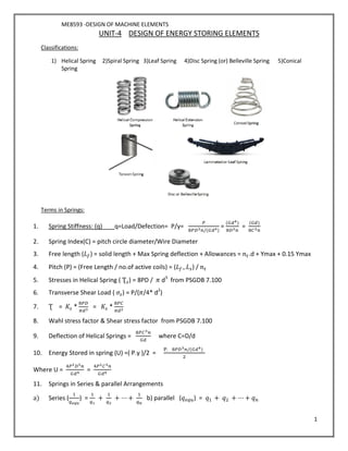
- 1. ME8593 -DESIGN OF MACHINE ELEMENTS 1 UNIT-4 DESIGN OF ENERGY STORING ELEMENTS Classifications: 1) Helical Spring 2)Spiral Spring 3)Leaf Spring 4)Disc Spring (or) Belleville Spring 5)Conical Spring Terms in Springs: 1. Spring Stiffness: (q) q=Load/Defection= P/y= /( ) = ( ) = ( ) 2. Spring Index(C) = pitch circle diameter/Wire Diameter 3. Free length ( ) = solid length + Max Spring deflection + Allowances = .d + Ymax + 0.15 Ymax 4. Pitch (P) = (Free Length / no.of active coils) = ( ) / 5. Stresses in Helical Spring ( Ʈ ) = 8PD / d3 from PSGDB 7.100 6. Transverse Shear Load ( ) = P/( /4* d2 ) 7. Ʈ = * = * 8. Wahl stress factor & Shear stress factor from PSGDB 7.100 9. Deflection of Helical Springs = where C=D/d 10. Energy Stored in spring (U) =( P.y )/2 = . /( ) Where U = = 11. Springs in Series & parallel Arrangements a) Series ( ) = + + ⋯ + b) parallel ( ) = + + ⋯ +
- 2. ME8593 -DESIGN OF MACHINE ELEMENTS 2 Design procedure for Helical Spring:- Step:1 Select suitable materials for spring according to load,deflection and usage Step:2 The pitch dia of coil D,is selected and choose spring index C value usually from(5 to 10) Step:3 Find wire dia d. Step:4 Wahl’s factor stress factor (Ks) can be calculated Step:5 Determine standard size of wire from PSG DB-7.105 Step:6 Find the number of coils.If number of coils is small-spring is soft so reduce mean dia and it increase dia of wire.If number of coil is large the mean coil dia may increase. Step:7 Decide the end conditions and select number of inactive coils from PSG DB-7.101 Step:8 Find the spring specifications 1)Dia of the spring (d) 2)Mean coil dia(D) 3)Number of active turns(n) 4)Solid length of the spring (Ls) 5)Free length of the spring (Lf) 6)Pitch od the coil (P) 7)Helix angle(α)=tan-1 (P/ D) 8)Spring Index(q)=P max/y Design procedure for Leaf spring:- Step:1 Select material and find permissible stress by selecting suitable FOS. Step:2 Assume number of leaves is not given usually 5 to 10. For railway wagons take upto 14. Step:3 Find effective length 2L. Step:4 σ= 6PL/nbt2 Assume number of leaves. Step:5 By assuming b (or) t, the thickness ranges 5-16,width 45-100 Step:6 Find max.stress deflection. Step:7 Find radius of curvature. Step:8 According to load Pb,centre bolt (or) band will be designed. Step:9 Design of pin the master leaf. Width of leaf=b , Length of pin b’ =(bt2 )*clearance , Load on pin= dp * b * Pb , Load on the pin=P/cos α Check for pin bending: Mb = (Load on pin * b’ ) /4 By assuming distributed uniform M= σb * z ,where z=(П/32)dp3 Check for pin shear: The pin will be double shear. = 2 * (П/4) *dp2 *Ʈ =Load on pin
- 3. ME8593 -DESIGN OF MACHINE ELEMENTS 3 Design of Belleville Springs (OR) Disc Springs: Applied load = P = ( ) ( ) ( (h- ) (h - y)t + ) From PSGDB 7.104 Spring constants M,C1,C2 (C1,C2 it depends upon ratio) M= ( ) ( ) From PSGDB 7.104 Maximum & minimum stresses are ( & ) : = ( ) ( ) ( (h- ) + t) , = ( ) ( ) ( (h- ) - t) = ( ) ( − 1) , = ( ) DESIGN OF FLYWHEEL A flywheel used in machines serves as a reservoir which stores energy during the period when the supply of energy is more than the requirement and release it during the period when the requirement of energy is more than supply. Co-efficient of fluctuation of speed = Ks = [ 2 max - 2 min] / 2 Fluctuation of energy ∆ = Emax - Emin Co efficent of fluctuation of energy CE = maximum Fluctuation of energy /work done per cycle
- 4. ME8593 -DESIGN OF MACHINE ELEMENTS 4 Work done per cycle =Tmean × θ θ =angle turned in radians per revolution, =2π in case of stream engine and two stroke I.C engine =4π in case of four stroke I.C engines energy stored in flywheel rim Flywheel Effect & COF of fluctuation of speed E = = = Change in kinetic energy = ∆ = 2 Ks , Fluctuation of energy ∆ = Emax - Emin k may be equal to mean radius of rim(R) because the thickness of rim is very small as compared to the diameter of rim substituting k=R Mass of flywheel m = ∆ Mass m = volume x density = ПD x A X ρ A=b*t b-width of rim , t- thickness of rim CONNECTING ROD The connecting rod may be of circular section, rectangular section or I- section. In high speed engines connecting rod of I- section is preferred.
- 5. ME8593 -DESIGN OF MACHINE ELEMENTS 5 For the selection of I-section, From PSGDB 7.122 Area of the section, a=11t2 Moment of inertia of the section about X-axis I xx= t4 Moment of inertia of the section about Y-axis I yy = t4 The ratio of should be 3 to 3.5 for safety design. Step1: Dimensions of I-section. Load due to maximum explosion pressure, FG = П d2 p Radius of gyration about the X- axis, K2 xx = 3.18t2 Rankine’s formula for buckling load Crippling stress (Fcr) = . Fcr= Factor of safety ×FG Rankine’s constant For cast iron, C = For mild steel, C = t- Thickness of I- section Height of the I- section, H=5t, Width of the I- section, B=4t. Step 2: Design of pin for small end Length of small end pin=L1 Diameter of small end pin= d1 =1.5 to 2 Load due to steam pressure, FG=L1×d1× Assume bearing pressure for small end= 10.5 to 15N/mm2 Assume FOS=6 to15 for heavy shock = 4 to 7 for light shock = 3 to 5 for steady shock Assume σ
- 6. ME8593 -DESIGN OF MACHINE ELEMENTS 6 Step 3: Design of pin for big end Length of big end pin=L2 Diameter of big end pin= d2 =1.25 to 1.50 Load due to steam pressure, FG=L2×d2× Assume bearing pressure for big end= 5 to 11 N/mm2 Step 4: Diameter of bolts: Angular velocity, = Radius of the crank, r = Inertia force Fi = × × r cos + Inertia force Fi = n× × × , [Assume and n] dc – core diameter of bolt n-Number of bolts Nominal diameter of bolt, db= . Step5: Thickness of bolt end cap, tc Distance between the bolt centers, X=(1.3 to1.75) d2 Maximum bending moment acting on the cap, Mc = × Mc = × Z (assume =100 N/mm2 ) Section modulus, Z = Width of cap, b =L2 tc- Thickness of bolt end cap