2. 1 Notations
1.1 Terms used in bevel gears
• a = Addendum.
• OP = Cone distance.
• d = Dedendum.
• DP = Pitch circle diameter.
• a = Addendum.
• θP = Pitch angle.
• Dd = Inside diameter.
1.2 Determination of pitch angle for bevel gears
• θP1 = Pitch angle for the pinion.
• ∴P2= Pitch angle for the gear.
• θS = Angle between the two shaft axes.
• DP = Pitch diameter of the pinion.
• DG = Pitch diameter of the gear.
• V.R. = Velocity ratio.
1.3 Formative or equivalent number of teeth for bevel gears - Tredgold’s approximation
• θP = Pitch angle or half of the cone angle.
• R = Pitch circle radius of the bevel pinion or gear.
• RB = Back cone distance or equivalent pitch circle radius of spur pinion or gear.
• T = Actual number of teeth on the gear.
1.4 Strength of bevel gears
• σo = Allowable static stress.
• Cv = Velocity factor.
• v = Peripheral speed in m / s.
• b = Face width.
• m = Module.
• y = Tooth form factor (or Lewis factor) for the equivalent number of teeth.
• L = Slant height of pitch cone (or cone distance).
• DG = Pitch diameter of the gear.
• DP = Pitch diameter of the pinion.
1.5 Design of a shaft for bevel gears
• P = Power transmitted in watts.
• NP = Speed of the pinion in r.p.m.
• dP = Diameter of the pinion shaft.
• τ = Shear stress for the material of the pinion shaft.
3. 2 Introduction
The bevel gears are used for transmitting power at a constant velocity ratio between two shafts whose axes
intersect at a certain angle. The pitch surfaces for the bevel gear are frustums of cones. The two pairs of cones
in contact is shown in Fig. 1.
Figure 1: Pitch surface for bevel gears.
3 Classification of Bevel Gears
1. Mitre gears. When equal bevel gears (having equal teeth and equal pitch angles) connect two shafts
whose axes intersect at right angle.
2. Angular bevel gears. When the bevel gears connect two shafts whose axes intersect at an angle other
than a right angle.
3. Crown bevel gears. When the bevel gears connect two shafts whose axes intersect at an angle greater
than a right angle and one of the bevel gears has a pitch angle of 90o
, then it is known as a crown gear.
The crown gear corresponds to a rack in spur gearing.
4. Internal bevel gears. When the teeth on the bevel gear are cut on the inside of the pitch cone.
Figure 2: Classification of bevel gears.
Note: The bevel gears may have straight or spiral teeth. It may be assumed, unless otherwise stated, that the
bevel gear has straight teeth and the axes of the shafts intersect at right angle.
4. 4 Terms used in Bevel Gears
The following terms in connection with bevel gears are important from the subject point of view :
1. Pitch cone. It is a cone containing the pitch elements of the teeth.
2. Cone center. It is the apex of the pitch cone. It may be defined as that point where the axes of two
mating gears intersect each other.
3. Pitch angle. It is the angle made by the pitch line with the axis of the shaft. It is denoted by θP .
4. Cone distance. It is the length of the pitch cone element. It is also called as a pitch cone radius. It is
denoted by OP . Mathematically, cone distance or pitch cone radius,
OP =
Pitch radius
sin θP
=
DP /2
sin θP1
=
DG/2
sin θP2
5. Addendum angle. It is the angle subtended by the addendum of the tooth at the cone center. It is
denoted by α Mathematically, addendum angle,
α = tan−1 a
OP
6. Dedendum angle. It is the angle subtended by the dedendum of the tooth at the cone centre. It is
denoted by β . Mathematically, dedendum angle,
β = tan−1 d
OP
7. Face angle. It is the angle subtended by the face of the tooth at the cone center. It is denoted by Φ .
The face angle is equal to the pitch angle plus addendum angle.
8. Root angle. It is the angle subtended by the root of the tooth at the cone center. It is denoted by θR.
It is equal to the pitch angle minus dedendum angle.
9. Back (or normal) cone. It is an imaginary cone, perpendicular to the pitch cone at the end of the
tooth.
10. Back cone distance. It is the length of the back cone. It is denoted by RB. It is also called back cone
radius.
11. Backing. It is the distance of the pitch point (P) from the back of the boss, parallel to the pitch point of
the gear. It is denoted by B .
12. Crown height. It is the distance of the crown point (C) from the cone center (O), parallel to the axis of
the gear. It is denoted by HC.
13. Mounting height. It is the distance of the back of the boss from the cone center. It is denoted by HM .
14. Pitch diameter. It is the diameter of the largest pitch circle.
15. Outside or addendum cone diameter. It is the maximum diameter of the teeth of the gear. It is
equal to the diameter of the blank from which the gear can be cut. Mathematically, outside diameter,
DO = DP + 2 a cos θP
16. Inside or dedendum cone diameter. The inside or the dedendum cone diameter is given by
Dd = DP − 2 d cos θP
5. Figure 3: Terms used in bevel gears.
5 Determination of Pitch Angle for Bevel Gears
Consider a pair of bevel gears in mesh, as shown in Fig. 3.
V.R. =
DG
DP
=
TG
TP
=
NG
NP
From Fig. 3, we find that
θS = θP1 + θP2 or θP2 = θS − θP1
sin θP2 = sin(θS − θP1) = sin θS cos θP1 − cos θS sin θP1
We know that cone distance,
OP =
DP /2
sin θP1
=
DG/2
sin θP2
⇒
sin θP2
sin θP1
=
DG
DP
= V.R.
∴ sin θP2 = V.R. × sin θP1
∴ V.R. × sin θP1 = sin θS cos θP1 − cos θS sin θP1
Dividing throughout by cos θP1 we get
V.R. tan θP1 = sin θS − cos θS tan θP1
⇒ tan θP1 =
sin θS
V.R. + cos θS
∴ θP1 = tan−1 sin θS
V.R. + cos θS
Similarly, we can find that
tanθP 2
=
sin θS
1
V.R.
+ cos θS
θP2 = tan−1 sin θS
1
V.R.
+ cos θS
6. Note: When the angle between the shaft axes is 90o
i.e. θS = 90o
, then
θP1 = tan−1 1
V.R.
= tan−1 DP
DG
= tan−1 TP
TG
= tan−1 NG
NP
θP2 = tan−1
(V.R.) = tan−1 DG
DP
= tan−1 TG
TP
= tan−1 NP
NG
6 Proportions for Bevel Gear
The proportions for the bevel gears may be taken as follows:
1. Addendum, a = 1 m
2. Dedendum, d = 1.2 m
3. Clearance = 0.2 m
4. Working depth = 2 m
5. Thickness of tooth = 1.5708 m
where m is the module.
Note: Since the bevel gears are not interchangeable, therefore these are designed in pairs.
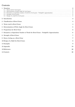
7 Formative or Equivalent Number of Teeth for Bevel Gears - Tredgold’s Ap-
proximation
We have already discussed that the involute teeth for a spur gear may be generated by the edge of a plane as
it rolls on a base cylinder. A similar analysis for a bevel gear will show that a true section of the resulting
involute lies on the surface of a sphere. But it is not possible to represent on a plane surface the exact profile
of a bevel gear tooth lying on the surface of a sphere. Therefore, it is important to approximate the bevel gear
tooth profiles as accurately as possible. The approximation (known as Tredgold’s approximation) is based
upon the fact that a cone tangent to the sphere at the pitch point will closely approximate the surface of the
sphere for a short distance either side of the pitch point, as shown in Fig. 4 (a). The cone (known as back cone)
may be developed as a plane surface and spur gear teeth corresponding to the pitch and pressure angle of the
bevel gear and the radius of the developed cone can be drawn. This procedure is shown in Fig. 4 (b). Now
from Fig. 4 (b), we find that
RB = R sec θP
We know that the equivalent (or formative) number of teeth,
TE =
2 RB
m
=
2R sec θP
m
= T sec θP
Figure 4:
7. Notes:
1. The action of bevel gears will be same as that of equivalent spur gears.
2. Since the equivalent number of teeth is always greater than the actual number of teeth, therefore a given
pair of bevel gears will have a larger contact ratio. Thus, they will run more smoothly than a pair of spur
gears with the same number of teeth.
8 Strength of Bevel Gears
The strength of a bevel gear tooth is obtained in a similar way as discussed in the previous articles. The modified
form of the Lewis equation for the tangential tooth load is given as follows:
WT = (σo × Cv) b π m y
L − b
L
Cv =
3
3 + v
, for teeth cut by form cutters
=
6
6 + v
, for teeth generated with precision machines
L =
DG
2
2
+
DP
2
2
Notes:
1. The factor L−b
L
may be called as bevel factor.
2. For satisfactory operation of the bevel gears, the face width should be from 6.3 m to 9.5 m, where m is
the module. Also the ratio L/b should not exceed 3. For this, the number of teeth in the pinion must not
less than 48√
1+(V.R.)2
, where V.R. is the required velocity ratio.
3. The dynamic load for bevel gears may be obtained in the similar manner as discussed for spur gears.
4. The static tooth load or endurance strength of the tooth for bevel gears is given by
WS = σe b π m y
L − b
L
The value of flexural endurance limit σe may be taken from Table 28.8, in spur gears.
5. The maximum or limiting load for wear for bevel gears is given by
Ww =
Dp b Q K
cos θP1
where DP , b, Q and K have usual meanings as discussed in spur gears except that Q is based on formative
or equivalent number of teeth, such that
Q =
2 TEG
TEG + TEP
9 Forces Acting on a Bevel Gear
Consider a bevel gear and pinion in mesh as shown in Fig. 5. The normal force (WN ) on the tooth is per-
pendicular to the tooth profile and thus makes an angle equal to the pressure angle (Φ) to the pitch circle.
Thus normal force can be resolved into two components, one is the tangential component (WT ) and the other
is the radial component (WR). The tangential component (i.e. the tangential tooth load) produces the bearing
reactions while the radial component produces end thrust in the shafts. The magnitude of the tangential and
radial components is as follows:
WT = WN cos Φ , and WR = WN sin Φ = WT tan Φ
8. These forces are considered to act at the mean radius (Rm). From the geometry of the Fig. 30.5, we find that
Rm = L −
b
2
sin θP1 = L −
b
2
Dp
2 L
Now the radial force (WR) acting at the mean radius may be further resolved into two components, WRH and
WRV , in the axial and radial directions as shown in Fig. 5. Therefore the axial force acting on the pinion shaft,
WRH = WR sin θP1 = WT tan Φ sin θP1
and the radial force acting on the pinion shaft,
WRV = WR cos θP1 = WT tan Φ cos θP1
A little consideration will show that the axial force on the pinion shaft is equal to the radial force on the gear
shaft but their directions are opposite. Similarly, the radial force on the pinion shaft is equal to the axial force
on the gear shaft, but act in opposite directions.
Figure 5: Forces acting on a bevel gear.
10 Design of a Shaft for Bevel Gears
In designing a pinion shaft, the following procedure may be adopted:
1. First of all, find the torque acting on the pinion. It is given by
T =
P × 60
2πNp
N-m
2. Find the tangential force (WT ) acting at the mean radius (Rm) of the pinion. We know that
WT = T/Rm
3. Now find the axial and radial forces (i.e. WRH and WRV ) acting on the pinion shaft as discussed above.
4. Find resultant bending moment on the pinion shaft as follows:
The bending moment due to WRH and WRV is given by
M1 = WRV × Overhang − WRH × Rm
and bending moment due to WT ,
M2 = WT × Overhang
∴ Resultant bending moment,
M = M1 + M2
5. Since the shaft is subjected to twisting moment (T) and resultant bending moment (M), therefore equiv-
alent twisting moment,
Te =
√
M2 + T2
6. Now the diameter of the pinion shaft may be obtained by using the torsion equation. We know that
Te =
π
16
× τd3
p
7. The same procedure may be adopted to find the diameter of the gear shaft.