Downloaded 911 times


![Measurement of Individual elements
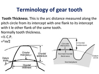
Measurement of tooth thickness
The permissible error or the tolerance on
thickness of tooth is the variation of actual
thickness of tooth from its theoretical value.
The tooth thickness is generally measured at
pitch circle and is therefore, the pitch line
thickness of tooth.
There are various methods of measuring the
gear tooth thickness.
(i) Measurement of tooth thickness by gear
tooth vernier calliper.
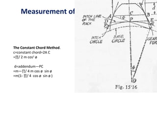
(ii) Constant chord method.
(iii) Base tangent method.
(iv) Measurement by dimension over pins.
Gear Tooth Caliper.
w=Nm. sin( 90∕N)
d= = Nm ∕2[1+2∕N− cos(90∕ N)]](https://image.slidesharecdn.com/gearthread-120918023938-phpapp01/85/Gear-thread-44-320.jpg)
![Measurement of Individual elements
The Base Tangent Method. (‘David Brown’
tangent comparator). In this method, the span
of a convenient number of teeth is measured
with the help of the tangent comparator. This
uses a single vernier calliper
BD=Nm cos ø [tanø –ø −∏ ∕ 2N +∏ S ∕ N ]](https://image.slidesharecdn.com/gearthread-120918023938-phpapp01/85/Gear-thread-47-320.jpg)


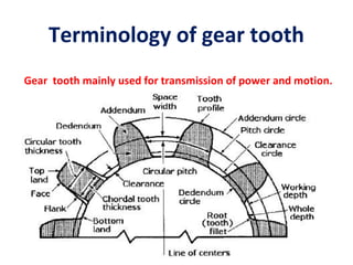
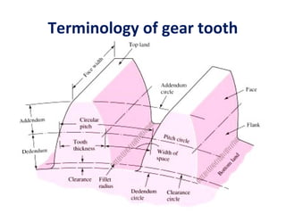
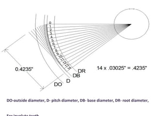
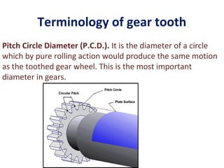
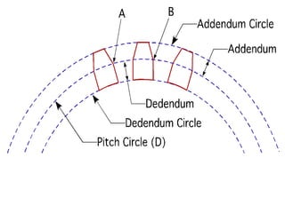
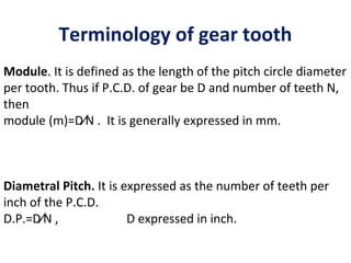
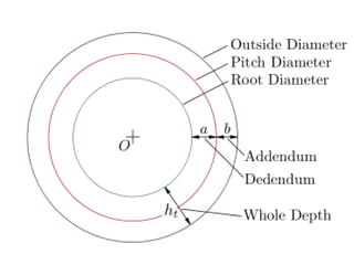
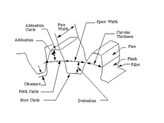
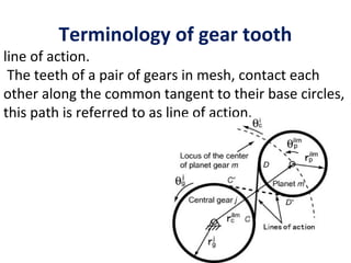
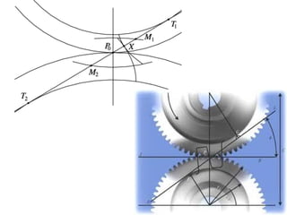
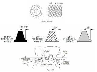
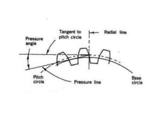
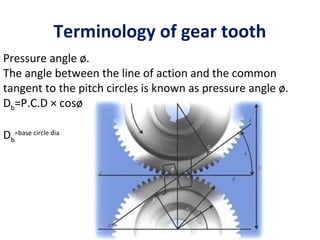
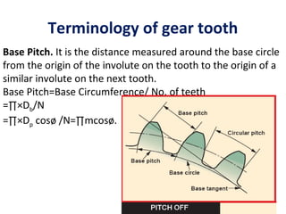
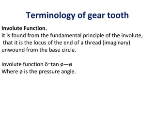
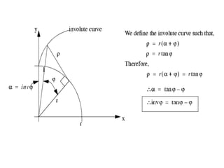
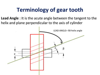
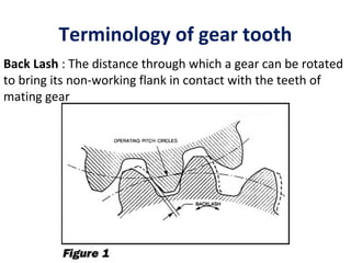
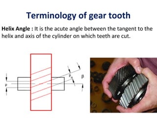
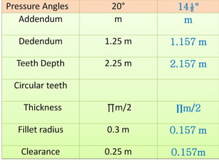
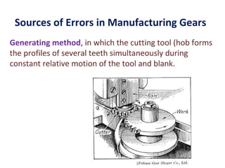
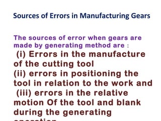
The document discusses various terms and measurements related to gear teeth. It defines terms like pitch circle, diametral pitch, module, addendum, dedendum, clearance, pressure angle, and helix angle. It also describes common methods for measuring individual elements of gear teeth, such as tooth thickness, pitch, and errors, using instruments like gear tooth calipers, constant chord method, and base tangent method. Sources of errors in gear manufacturing by generating and reproducing methods are also outlined.