

Recommended
Recommended
More Related Content
What's hot
What's hot (19)
Similar to Ethercat twincat e
Similar to Ethercat twincat e (20)
Recently uploaded
Recently uploaded (20)
Ethercat twincat e
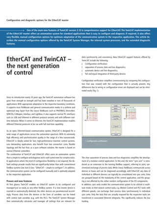
- 1. Since its introduction nearly 10 years ago, the TwinCAT automation software has gone from strength to strength and has been installed in tens of thousands of applications. With appropriate adaptation to the respective boundary conditions, it supports most fieldbuses and general communication media in a uniform and optimized way. Apart from the classic fieldbuses such as PROFIBUS, DeviceNet, SERCOS, CANopen, Interbus, and Lightbus, it also supports normal PC interfaces such as USB and Ethernet in different protocol variants and with different real- time behavior. When it comes to Ethernet, the TwinCAT implementation enables different Ethernet protocols to be run with full real-time capability. As an open, Ethernet-based communication system, EtherCAT is designed for a wide range of applications across the automation spectrum. With its extremely high efficiency and synchronization quality in the range of a few nanoseconds, EtherCAT is ideally suited for fast, high-performance machine control systems. Less demanding applications also benefit from low connection costs, flexible topology and the fact that, as a pure software solution, the master is based on normal Ethernet controllers. The combination of TwinCAT and EtherCAT offers users an automation system that is simple to configure and diagnose and is well suited even for complex tasks. In applications where this kind of configuration flexibility is not required, the de- fault settings provide results that are significantly better than with conventional fieldbus systems (see text in box: “EtherCAT – simple to configure”). In addition, the communication system can be configured manually and is optimally adapted to the respective application. Proven and new features At first glance, TwinCAT enables an EtherCAT system to be configured and managed just as easily as any other fieldbus system. If a new master device is inserted or automatically detected, the other devices are parameterized accord- ingly. Process data from the devices in the form of variables can be linked with control task variables (e.g. with the PLC). The TwinCAT System Manager then automatically calculates and manages all settings that are relevant for data synchronicity and consistency. New EtherCAT support features offered by TwinCAT include the following: | Configuration verification; | separation of process data and bus diagnostics; | automatic device and line diagnostics; | full and equal integration of third-party devices. Configuration verification simplifies commissioning by comparing the configura- tion that was created with the configuration that is actually present. Any differences due to wiring or configuration errors are displayed and can be elimi- nated easily (Fig. 1). One of the main new features of TwinCAT version 2.10 is comprehensive support for EtherCAT. The TwinCAT implementation of the EtherCAT master offers an automation system for standard applications that is easy to configure and diagnose. If required, it also offers very flexible, manual configuration options for optimum adaptation of the communication system to the respective application. This article de- scribes the manual configuration options offered by the TwinCAT System Manager, the internal system processes, and the extended diagnostic features. Configuration and diagnostic options for the EtherCAT master EtherCAT and TwinCAT – the next generation of control 1. Configuration verification The clear separation of process data and bus diagnostics simplifies the develop- ment of a modular control application. To this end, the term “sync unit” is intro- duced as an extension to the existing fieldbus support, referring to joint, syn- chronized exchange of process data.While classic fieldbuses communicate across devices or buses and can be diagnosed accordingly, with EtherCAT, any data of individual or different devices can logically be consolidated into sync units. Data are grouped based on the modularity of the control application, and the group- ing is not affected by the rather random configuration of the I/O components. In addition, sync units enable the communication system to be utilized in multi- task mode, so that several control tasks, e.g. Motion Control and PLC tasks with different speeds, can exchange their process data synchronously in individual sync units. Only the data that are actually required for the respective tasks are transferred in associated Ethernet telegrams. This significantly reduces the bus loading.
- 2. Modularcontrolstructure Sync unit 3 Sync unit 2 Sync unit 1 DataexchangePhysicalbusstations Bus diagnostic Process data diagnostic (1 bit) Frame 1 Frame 0 Frame 1 t EtherCAT I/O EtherCAT drives M M Task 0 Task 1 M Frame 0 Sync units for modular control architecture The aim of a modular control architecture is to be able to develop and manage each module as independently as possible. A module defines a certain block of process data that have to be synchronously and consistently exchanged with the periphery, i.e. a sync unit. The I/O components involved in the data exchange should be transparent for the module, i.e. only the validity of the data is signifi- cant. To this end, each sync unit offers cycle-synchronized process data diagnos- tics indicating whether all the data of the sync unit are valid. If individual or all sync units indicate invalid process data, an associated bus diagnostic can be run in a separate part of the control application in order to locate the cause of the problems. Sync units facilitate structuring of the control tasks, particularly in applications in which parts of the machine continue to run if others are affected by unscheduled failure or are deactivated intention- ally. The granularity of the sync units is determined by the EtherCAT devices. Each device defines one or several process data ranges that it can exchange synchro- nously and consistently. EtherCAT supports a wide range of devices, ranging from two-bit digital input terminals to devices integrating a fully, subordinate fieldbus (e.g. a PROFIBUS master). How many independent process data ranges an individual device can support will depend on its implementation and on the resources of the EtherCAT Slave Controller (Sync Manager and FMMU channels) (Fig. 2). Process data diagnostics A significant advantage of EtherCAT is that process data communication gener- ates no additional overhead for the individual devices. The sync unit to be ex- changed is merely extended by the associated device data. To this end, all data ranges of the different devices of a sync unit involved are configured in a logical memory area and exchanged via an individual EtherCAT command. Each EtherCAT command has a “working counter” that is automatically incremented by all devices that process the associated command, providing an effective diag- nostic tool. During each cycle the controller compares this counter with the ex- pected value and decides whether the sync unit data are valid. If 20 devices have been consolidated into a sync unit, for example, after associ- ated processing, the working counter must have been incremented by the devices and match the expected value. If this is not the case, all process data from this sync unit are declared invalid, because the validity of individual data is not established during each cycle. Provided the sync units have been cleverly se- lected according to the modularity of the application, this information is, in fact, not required at this point. On the contrary, this purely Boolean and cycle-syn- chronous information can be managed for the module much more generally than a plethora of different, system-specific diagnostic data.Troubleshooting can then be dealt with by the bus diagnostics and does not have to be synchronized with the cycle. Sync units in the TwinCAT System Manager The TwinCAT System Manager is responsible for managing and calculating the sync units and the resulting communication configuration. This calculation is carried out largely automatically, based on the boundary conditions resulting from the EtherCAT device structure and the links between the different variables. Currently, the System Manager requires assistance for the application-specific allocation of the individual process data ranges of the EtherCAT devices to con- trol modules. To this end the process data ranges are assigned freely definable names. All device process data ranges that have the same name and are ex- changed in the same temporal context (tasks) are consolidated within a sync unit. All process data ranges assigned to the “feed unit” control module, for example, will also have this name. The control module does not have to deal with the cur- rent physical distribution of the I/O devices. Instead, during each cycle it is in- formed via a diagnostic bit whether their relevant data are valid (Fig. 3). 2. Modular EtherCAT control structure: As an example, the diagram shows the allocation of the process data of the individual control modules, the temporal- ly dependent transfer (here via two independent tasks), and the free distribu- tion of the process data to the bus devices.
- 3. The sync unit names can either be allocated directly at the device or, as shown in the figure, via a common list. In future extensions of the sync unit concept, the sync units will also be compiled purely via links and the required information (i.e. which data belong to a particular control module) will come from the source, e.g. the PLC project. The sync units thus become a central organizational unit of the modular control architecture. From the sync unit allocation shown in the example, the System Manager gener- ates the required Ethernet telegrams (at least one telegram for each task) and the associated sync units via individual, embedded EtherCAT commands. All process data ranges that are not explicitly allocated are automatically assigned to the nameless default sync unit. The telegrams generated in this way (frame 0 and 1) and the EtherCAT commands embedded within them are shown in the table in Fig. 4. Frame 0 is assigned to the NC task and exchanged synchronously with a cycle time of 1 ms. The frame contains three EtherCAT commands. The first two commands deal with process data communication and exchange the default and feed unit sync unit data via a logical read/write command (LRW). For both commands, the expected value for the working counter is 3. In this example, they coincidentally also have the same user data length, i.e. 8 bytes. The controller can now independently monitor the working counters of the two sync units and determine whether the associated da- ta have been exchanged correctly and whether they are valid.The third EtherCAT command is generated for internal purposes and is used for checking which de- vices want to communicate acyclically via their mailbox. Frame 1 is assigned to the PLC task.The first three EtherCAT commands exchange the data for the default, intake and feed unit sync units.All data are updated with the cycle of the PLC task. The fourth command is generated for internal purpos- es.Via broadcast read (BRD), it reads the state of the state machine of all devices and is used for automatic bus diagnostics. For each EtherCAT command, and al- so for each exchanged sync unit, one bit indicating the validity of the data is avail- able for the purpose of process data diagnostics. Bus diagnostics The bus diagnostics is largely independent of the process data diagnostics. It pro- vides information about the state of the individual devices and the quality of the communication connections. Each EtherCAT device has a uniform state machine that indicates the communication state of the device and can be used to change this state. Usually, state transitions are requested by the master and executed by the device. In exceptional cases, a device may change its state independently. TwinCAT au- tomatically monitors the device states. In addition, fault counters and link infor- mation of the individual devices are diagnosed as required or at regular intervals. The fault counters are integrated in the EtherCAT Slave Controller and provide in- formation about the quality of each individual transmission link. Since EtherCAT only involves point-to-point connections and each of these connections has its own fault counter, problematic connections can be located precisely. The state and diagnostic information is available for application-specific bus diagnostics in the PLC, both via process data mapping and acyclically via ADS (Fig. 5). The high degree of flexibility in terms of the EtherCAT wiring topology is no doubt a further highlight of the system, although from a diagnostic point of view it al- so represents an additional source of error, particularly during commissioning. Here too, the EtherCAT Slave Controller offers a suitable diagnostic tool, i.e. the connection states (links) of all possible ports can be read. Deviations from the re- quired configuration are detected and displayed in the state of the respective de- vice. Provided the target topology is known, this enables an incomplete system 3. Sync unit assignment 4. Telegram distribution of the sync units
- 4. EtherCAT – simple to configure In conjunction with TwinCAT, EtherCAT offers innovative, high-perform- ance options for perfectly adapting the communication to your applica- tion requirements. Not all applications require this high degree of con- figuration flexibility. Since EtherCAT is very fast even with the default settings, the results are significantly better than with conventional fieldbus systems. In this case, the simplicity of the system comes into its own – the system usually requires much less configuration effort than in the past. First of all, manual adjustment of the node addresses on the field de- vices is no longer required. Rotary selection and dip switches and the associated settings in the TwinCAT System Manager are also a thing of the past. Unlike with other Industrial Ethernet approaches, most devices do not require IP addresses to be entered or configured. Setting of the baud rate (depending on the fieldbus, the network size and the applica- tion requirements) is also no longer required, and most limitations im- posed by the network topology are also a thing of the past: EtherCAT supports line topology, drop lines, star wiring and flexible tree struc- tures. There are practically no restrictions in terms of the number of network nodes: 65,535 nodes for each segment should suffice. In the TwinCAT System Manager, the network components are merely selected and arranged in the right order. If the network is already online, this can be done automatically. TwinCAT automatically allocates the logical node addresses. Additional devices can be integrated at a later stage without changes to the existing addresses. During start-up, the actual configuration can be compared with the specified configura- tion, so that cabling errors or invalid device selections are detected quickly and reliably. While the limited bandwidth of fieldbus systems often requires carefully considered configuration of the communication features in order to meet the requirements of the application, this step is usually no longer required with EtherCAT due to its outstanding performance. Obviously, the allocation of the physical process data to the logical process data, i.e. the so-called mapping, still has to be configured. This is done in the TwinCAT System Manager in the usual way by link- ing the bus system process variables with the control task variables. 5. Online-side System Manager Conclusions EtherCAT support in TwinCAT is not limited to pure utilization of the high-per- formance communication system. Logical addressing, the primary purpose of which is to achieve very high usable data rates, is also used for device-inde- pendent structuring of the process data. The process data can be grouped into sync units to match the requirements of the control application (i.e. not on the basis of how they were wired due to geographic and electrical boundary condi- tions). This enables bus-independent and, therefore, application-independent de- velopment of individual control modules. The differentiation between process data and bus diagnostics also facilitates in- dependent development of these control modules. Process data diagnostics pro- vides the individual modules with synchronized information about the validity of the respective process data for each cycle. Bus diagnostics monitors the applica- tion-specific configuration of the communication system and provides detailed information about operating states and faults of individual devices. (with some devices missing) to be initialized. The missing devices and communi- cation connections can be identified via the device states and can be integrated later while the system is running.