
Recommended
More Related Content
What's hot
What's hot (19)
Similar to The Design of Multi-Platforms Rail Intelligence Flatness Detection System
Similar to The Design of Multi-Platforms Rail Intelligence Flatness Detection System (20)
More from IJRESJOURNAL
More from IJRESJOURNAL (20)
Recently uploaded
Recently uploaded (20)
The Design of Multi-Platforms Rail Intelligence Flatness Detection System
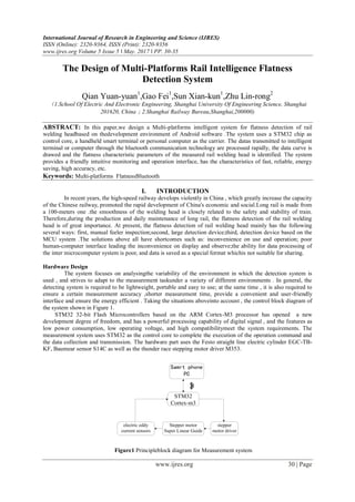
- 1. International Journal of Research in Engineering and Science (IJRES) ISSN (Online): 2320-9364, ISSN (Print): 2320-9356 www.ijres.org Volume 5 Issue 5 ǁ May. 2017 ǁ PP. 30-35 www.ijres.org 30 | Page The Design of Multi-Platforms Rail Intelligence Flatness Detection System Qian Yuan-yuan1 ,Gao Fei1 ,Sun Xian-kun1 ,Zhu Lin-rong2 (1.School Of Electric And Electronic Engineering, Shanghai University Of Engineering Science, Shanghai 201620, China;2.Shanghai Railway Bureau,Shanghai,200000) ABSTRACT: In this paper,we design a Multi-platforms intelligent system for flatness detection of rail welding headbased on thedevelopment environment of Android software .The system uses a STM32 chip as control core, a handheld smart terminal or personal computer as the carrier. The datas transmitted to intelligent terminal or computer through the bluetooth communication technology are processed rapidly, the data curve is drawed and the flatness characteristic parameters of the measured rail welding head is identified. The system provides a friendly intuitive monitoring and operation interface, has the characteristics of fast, reliable, energy saving, high accuracy, etc. Keywords: Multi-platforms FlatnessBluetooth I. INTRODUCTION In recent years, the high-speed railway develops violently in China , which greatly increase the capacity of the Chinese railway, promoted the rapid development of China's economic and social.Long rail is made from a 100-meters one .the smoothness of the welding head is closely related to the safety and stability of train. Therefore,during the production and daily maintenance of long rail, the flatness detection of the rail welding head is of great importance. At present, the flatness detection of rail welding head mainly has the following several ways: first, manual feeler inspection;second, large detection device;third, detection device based on the MCU system .The solutions above all have shortcomes such as: inconvenience on use and operation; poor human-computer interface leading the inconvenience on display and observe;the ability for data processing of the inter microcomputer system is poor, and data is saved as a special format whichis not suitable for sharing. Hardware Design The system focuses on analysingthe variability of the environment in which the detection system is used , and strives to adapt to the measurement taskunder a variety of different environments . In general, the detecting system is required to be lightweight, portable and easy to use; at the same time , it is also required to ensure a certain measurement accuracy ,shorter measurement time, provide a convenient and user-friendly interface and ensure the energy efficient . Taking the situations aboveinto account , the control block diagram of the system shown in Figure 1. STM32 32-bit Flash Microcontrollers based on the ARM Cortex-M3 processor has opened a new development degree of freedom, and has a powerful processing capability of digital signal , and the features as low power consumption, low operating voltage, and high compatibilitymeet the system requirements. The measurement system uses STM32 as the control core to complete the execution of the operation command and the data collection and transmission. The hardware part uses the Festo straight line electric cylinder EGC-TB- KF, Baumear sensor S14C as well as the thunder race stepping motor driver M353. Samrt phone PC STM32 Cortex-m3 Stepper motor Super Linear Guide stepper motor driver electric eddy current sensors Figure1 Principleblock diagram for Measurement system
- 2. The Design Of Multi-Platforms Rail Intelligence Flatness Detection System www.ijres.org 31 | Page Design Ideas An eddy current sensor is installed on a 1-meter long linear cylinder, andthe host computer sends out detection command . The embedded control system arranged in the measuring device controls the stepper motor to rotate, by this means the high-precision eddy current sensor is driven to do a straight line movementalong the guide rail upon the slide table . At the same time, the data acquisition system collects the sensor signals high- speedcontinuously , and the data collection is completed until the end of the trip. At this point, the system enters the standby mode of reverse measurement, meanwhile, the embedded control system processes the datas and sends them to the host computer to be processed and the measurement results is displayed. In the same way, after receiving the detection command in the reverse measurement mode, the motor reverses and the sensor moves in the reverse direction. The data acquisition system carries out high-speed continuous sampling on the rail surface until the start of the cylinder. At this time, the system enters the forward measurement mode ,and the datas are processed and returned to the host computer and the measurement results are displayed . At the first time to start , in order to ensure that the detection system presents the data according to the detection direction of the forward easurement mode,the sensor position is automatically restored to the cylinder start position .System requirements are shown as fllow : Detection distance: 950mm; detection accuracy: less than 50um; the detection time is less than 15s. Working Principle of Control System System schematic diagram (part) is shown in Figure 2 Figure2Principle diagram of the embedded control system Working principle: The control system is based on STM32F103C6T6 controller, and the chip integrates 12-bits A/D converter, timer, synchronous serial port and so on. It can achieve data acquisition, stepper motor control, data transmission and other functions. In order to improve the accuracy of A/D conversion, the voltage reference chip REF192 is used , by collecting sensors and external reference voltage at the same time, the unknown signal is compared with the known external referencevoltage to reduce the impactcaused by the external temperature changes , and obtain accurate voltage datas. The electric cylinder driven by the stepper motorcarries the sensor for scanning. The travellength of the stepper motor is determined by the number of control pulse, and the speed is controlled by the frequency of the pulse. In order to adapt to the acceleration or deceleration curve of the stepper motor, and scanwith precise fixed length ,the system uses a pulse generator cascaded by two timers in the chip to form a variable frequency, variable number pulses to control the stepper motor. Considering the battery capacity and the needs of field operations, with the purse of extending the battery lifeas far as possible , the embedded system automatically enters the standby state when the system standby ,and waits for the wake-upsignal to start detecting . The system also designs the one-button switch circuit for the zero standby current , the system is energized,after the open or shutdown button is pressed ,the controller starts and controls the solid state relay paralleledon the open, shutdown button to complete the self- locking. With this circuit, the timer will shutdown if the system does not be operated at a long time , the circuit is shown in Figure 3.
- 3. The Design Of Multi-Platforms Rail Intelligence Flatness Detection System www.ijres.org 32 | Page Figure3 Standby switching circuit Software Design The wireless communication technology between multiple-platforms structure and the embedded system has been considered in this system , and it achieves an unified communications solutions between variety of equipments and embedded system , also designs the program based on embedded system to achieve hardware control, data acquisition, data communication, has realized the unity storage solutions of datas from multiple platforms . Software architecture is shown in figure 4. Android is a Linux-based open source operating system, is mainly used in software design for portable devices, in this environment, the design has the following modules: Android系统软件 检测功能 数据存储 检测模块 通信模块 自校功能 显示模块 数据格式化模 块 数据管理模块 Figure4 Software architecture of the system Detection Module: this module is used to set up necessary marking parameters, send out the measurement instruction to the data acquisition system through communication module, and get the testing data; After further processing and optimization ,the data is transmitted to the display module and data formatting module. communication module: It is an important part of the complete set of testing system, the bridge between PC and data acquisition system. This system follow standard wireless communication protocol, and use the multi-threading technology to complete data communication between PC and data acquisition system. Self correcting module: different work environment, temperature and humidity will cause different degrees of deformation to the mechanical part, the self-calibration need to be done to eliminate the system error when the work environment changes. Display module: it is a public module shows the data dealed and the test datas , related judgment results are presented to the operator by means of graphics on it . Data storage: This moduel will format the detected datas into an unified format and store them in the data management module.Because there are many different platforms and PC operating systems, the unified data format which is useful in different platform and different operating system is indispensable. Data management module: completes the founction of data storage and reload.
- 4. The Design Of Multi-Platforms Rail Intelligence Flatness Detection System www.ijres.org 33 | Page Programming Introduction The example program for packet processing : Packet processing is divided into two parts, one is to parse the received packet, and then trigger the corresponding events;Another is to generate the corresponding packets according to the corresponding command and the packets are sented by the bluetooth module. The flow diagram of Data reception is shown in figure 5. Receive data Wait for the header of packet N Is the header of packet Y endN Wait for the length of packet Y end Wait for the length of packet Get the length of packet Y Wait for the main data end The length got =the length of packet Wait for the main data N end Wait for the header of packet Y end Figure5 Flow chart of data reception The specific program code is shown as follows: private void bulidPacket(String cmdName,byte[] data) { if(_isSendingPacket) return; _isSendingPacket = true; int size = 10 + (data == null?0: data.length); byte[] bytes = new byte[size]; bytes[0]= (byte) 0xff; bytes[1]= 0x0; bytes[2]= (byte) (size& 0xff); bytes[3]= (byte) (size >> 8); bytes[4]= (byte) 0xff; bytes[5]= (byte) 0xff; bytes[6]= (byte) 0xff; bytes[7]= (byte) 0xff; bytes[8]= (byte) cmdName.charAt(0); bytes[9]= (byte) cmdName.charAt(1); if(data != null) { for (int i =0; i < data.length; i++) { bytes[i+10]= data[i];
- 5. The Design Of Multi-Platforms Rail Intelligence Flatness Detection System www.ijres.org 34 | Page } } _rDeviceBt.SendDate(bytes); _isSendingPacket = false; } Experiment and Result Analysis In the condition of laboratory, the experiment for multi-platform portable intelligent rail flatness detection system was carried out about the accuracy and repeatability of datas . Table1 Test results Number calibration value (mm) first time (mm) second time (mm) third time (mm) 1 0.02 0.023 0.019 0.017 2 0.05 0.051 0.053 0.048 3 0.1 0.104 0.101 0.099 4 0.2 0.198 0.201 0.203 5 0.35 0.351 0.353 0.348 6 0.5 0.504 0.501 0.503 7 0.65 0.648 0.649 0.651 8 0.8 0.801 0.8 0.803 9 0.9 0.901 0.902 0.899 10 1.0 1.001 1.004 1.003 During the experiment ,10 thickness ranging feelers are placed on a 00 level ruler and detected by the system designed in this paper. the experiment is repeated three times and the results are shown in table 1. the measurement error is within 0.01 mm and repeatability within 0.005 mm , Comply with the design requirements . The operation interface on intelligent terminal is shown in figure 7. Figure7 Operation interface on Terminal II. CONCLUSION In this paper , we design the software and hardware of the intelligent detection system for the rail and implements multiple-platforms detecting the surface roughness of rail welding head and realizes the unified storage of multiple-platforms data . Various flexible cases are adopted and the the follow-up maintenance costs significantly reduced. the test of Shanghai design institute proves that the system meets the design requirements
- 6. The Design Of Multi-Platforms Rail Intelligence Flatness Detection System www.ijres.org 35 | Page REFERENCES [1]. Yu, J. Q. ,&Yu, B.(2014). Development and application of STM32F series ARM Cortex M3 nuclear micro controller.Tsinghua university press. [2]. James,W. C. (Eds),&Ye, B. (2011). c # design pattern. Science press. [3]. Ning, Y. P. ,&Liu ,Z. F.(2005) .The current research status of high precision straightness measurement technology at home and abroad. Modern manufacturing engineering,6,21-30. [4]. Wang ,Y. S. (2010). Development tour of the Android platform . Bei jing,Mechanical industry press. Author Information Yuanyuan Qian Shanghai University of Engineering Science Longteng road333, songjiang district, Shanghai Contact e-mail:1638581957@qq.com Fei Gao Shanghai University of Engineering Science Longteng road333, songjiang district, Shanghai Xiankun Sun Shanghai University of Engineering Science Longteng road333, songjiang district, Shanghai Linrong Zhu Shanghai railway bureau Temmoku east road 80,Shanghai