
Recommended
More Related Content
Similar to Automation and Robotics 20ME51I Week 3 Theory Notes.pdf
Similar to Automation and Robotics 20ME51I Week 3 Theory Notes.pdf (20)
More from Gandhibabu8
More from Gandhibabu8 (6)
Recently uploaded
Recently uploaded (20)
Automation and Robotics 20ME51I Week 3 Theory Notes.pdf
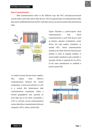
- 1. PLC Data communica on WEEK: 03 Page 1 Data Communications Data communications refers to the different ways that PLC microprocessor-based systems talk to each other and to other devices. The two general types of communications links that can be established between the PLC and other devices are point-to-point links and network links. Figure illustrates a point-to-point serial communications link. Serial communications is used with devices such as printers, operator workstations, motor drives, bar code readers, computers, or another PLC. Serial communications interfaces are either built into the processor module or come as separate modules. A serial module installed in each controller is normally all that is required for two PLCs of the same manufacturer to establish a point-to-point link. As control systems become more complex, they require more effective communications between the system components. A local area network or LAN is a system that interconnects data communications components within a limited geographical area, typically no more than one or two miles. Essentially, a LAN is a private, on-site communications system that allows communication between computers, PLCs, robots, and the like.
- 2. PLC Data communica on WEEK: 03 Page 2 Serial communication: Serial communication is a method of transferring data between two devices by sending it one bit at a time sequentially over a single communication line or channel. It is a common method used for data exchange between various devices such as computers, PLC, microcontrollers, and peripherals. The most common types of serial communication protocols include (Recommended standard RS-232, RS-485), UART (Universal Asynchronous Receiver-Transmitter), SPI (Serial Peripheral Interface), and I2 C (Inter-Integrated Circuit-IIC). Serial communication offers several advantages, including simplicity, cost- effectiveness, and the ability to transmit data over long distances using appropriate protocols. However, it is generally slower compared to parallel communication methods. Parallel communication Parallel communication is a method of transmitting multiple data bits simultaneously over multiple wires or channels. Parallel communication allows for faster data transfer rates. In parallel communication, each data bit is assigned to a separate wire or channel. This means that multiple bits can be transmitted simultaneously, reducing the overall transmission time. For example, in an 8-bit parallel communication system, eight wires are used, with each wire carrying one bit of data. Parallel communication can be implemented using various interfaces, such as parallel ports, parallel buses, or parallel interfaces on integrated circuits.
- 3. PLC Data communica on WEEK: 03 Page 3 However, parallel communication also has some limitations. 1. Maintaining the synchronization of the data transmitted over multiple wires. 2. Any differences in wire lengths or delays can cause timing issues and introduce errors in the received data. 3. Another limitation is the increased complexity of hardware design and the larger number of wires or channels required.
- 4. PLC Data communica on WEEK: 03 Page 4 ASCII (American Standard Code for Information Interchange) Functions PLC (Programmable Logic Controller) ASCII functions are a set of instructions or functions provided by a PLC programming environment that allow communication and data exchange between the PLC and external devices using ASCII characters. Some commonly used PLC ASCII functions are: 1. ASCII to Integer Conversion: This function converts ASCII characters representing numeric values into their corresponding integer values. It is useful when receiving numeric data from external devices in ASCII format. 2. Integer to ASCII Conversion: This function converts integer values into their corresponding ASCII characters. It is useful when sending numeric data to external devices that expect ASCII representation. 3. ASCII Character Comparison: This function compares two ASCII characters and determines if they are equal, greater than, or less than each other. It is often used for decision-making in PLC programs. 4. ASCII String Concatenation: This function combines multiple ASCII strings into a single string. It is useful for constructing messages or commands to be sent to external devices. Ex: string1 = "Hello, " string2 = "world!" concatenated_string = string1 + string2 Output: Hello, world! 5. ASCII String Length: This function determines the length of an ASCII string, i.e., the number of characters in the string. It is often used for validation and handling variable- length input data. Ex: string = "Hello, world!" Length= 13 6. ASCII to BCD (Binary Coded Decimal) Conversion: This function converts ASCII characters representing decimal numbers into their BCD equivalents. It is useful when working with BCD-based systems or when interfacing with devices that use BCD. 7. BCD toASCII Conversion: This function converts BCD values into their corresponding ASCII characters. It is the reverse of the ASCII to BCD conversion and is used when sending BCD data to external devices.
- 5. PLC Data communica on WEEK: 03 Page 5 Networking architecture PLC networking architecture refers to the arrangement and configuration of PLC devices in a networked environment. PLCs are industrial control systems used to automate processes in manufacturing, industrial, and infrastructure settings. 1. Centralized PLC Architecture: In this architecture, a central PLC or a small number of PLCs are responsible for controlling and coordinating the entire system. These PLCs are typically located in a central control room or a control panel. 2. Distributed PLC Architecture: In this, multiple PLCs are distributed throughout the system, each responsible for controlling a specific section or subsystem. These PLCs are interconnected through a network and communicate with each other to coordinate system- wide operations. 3. Redundant PLC Architecture: This architecture aims to ensure system availability and reliability by introducing backup or redundant PLCs. Redundancy helps mitigate the impact of failures, minimizing downtime and improving system resilience. Redundant PLCs work in parallel, monitoring each other's status and taking over control if a failure is detected in the primary PLC.
- 6. PLC Data communica on WEEK: 03 Page 6 OSI model of PLC networking International Organization for Standardization (ISO) has defined a seven- layer standard protocol system known as the Open Systems Interconnection (OSI) model. The model is a framework for developing a co-ordinated system of standards. The layers are as outlined below. 1. Physical layer: This layer of the OSI model defines connector and interface specifications, as well as the medium (cable) requirements. The layer moves the data in the form of electromagnetic or optical signal across the transmission medium. It is responsible for the movement of data from one node to next. 2. Data link layer: It provide reliable communication over the physical layer interface. Layer 2 manages the ordering of bits, packets, to and from data segments. The ensuing result is called frames. Data links are responsible for moving frames from one node to another. A data link layer Create and detect frame boundaries and detect an error and produce an acknowledgement and retransmit the data. Its responsibility includes, Packet addressing, Media access control, Format the frame used to encapsulate data, Error notification on the Physical layer, Managing of error messaging specific to the delivery of packets.
- 7. PLC Data communica on WEEK: 03 Page 7 3. Network layer: It is responsible for the delivery of individual packets from the source host to destination host. It defines the most optimum path the packet should take from the source to the destination. If the message is too large to be transmitted from one node to another on the data link layer between those nodes, the network may implement message delivery by splitting the message into several fragments at one node, sending the fragments independently, and reassembling the fragments at another node. 4. Transport layer: Purpose of this layer is to provide a reliable mechanism for the exchange of data between two processes in different computers. This layer transports the data in a sequential manner with no loses. Transport layer divides large messages into small packets so that easily transmitted. Main functions of transport layer are - guarantee data delivery, flow control, error detection and error recovery. 5. Session layer: Session layer provides a mechanism for controlling the dialogue between the two end systems. It defines how to start, control and end conversations (called sessions) between applications. The Session layer utilizes the virtual circuits created by the Transport layer to establish communication sessions. It establishes, terminates, and monitors communication sessions between applications. Session layer is also responsible for terminating the connection.
- 8. PLC Data communica on WEEK: 03 Page 8 6. Presentation layer: It defines the format of communication data is to exchange between to system. And this layer is responsible for translation, Protocol conversion, Character set conversion, Interpretation of graphics commands, compression, and encryption. 7. Application layer: Application layer contains management functions to support distributed applications. Examples of application layer are applications such as file transfer, electronic mail, remote login etc.
- 9. PLC Data communica on WEEK: 03 Page 9 TCP/IP Protocol: Introduction to IP Address, Subnet Mask, Networking Devices, Network topology TCP/IP (Transmission Control Protocol/Internet Protocol) is a suite of communication protocols that provide reliable and standardized data transmission over networks. It consists of layers, including the Application layer, Transport layer, Internet layer, and Network interface layer. TCP/IP is composed of two main protocols: 1. Transmission Control Protocol (TCP): a. TCP is a connection-oriented protocol, it establishes a consistent and ordered data transmission channel between two devices before data exchange begins. b. It breaks data into packets, which are sent over the network, and ensures that all packets arrive correctly at their destination and in the correct order. c. If any packets are lost or damaged during transmission, TCP automatically requests retransmission. 2. Internet Protocol (IP): a. IP is a connectionless protocol, responsible for routing packets of data across interconnected networks to their planned destinations. b. Each device on the network is assigned a unique IP address, which serves as its identification. c. IP packets contain the source and destination IP addresses, allowing routers to forward the packets along the best path to reach the destination device. d. IP packets are not guaranteed to arrive at their destination or to be received in the correct order.
- 10. PLC Data communica on WEEK: 03 Page 10 TCP/IP operates on a layered model, consisting of four layers: 1. Application Layer: This includes application-specific protocols such as HTTP (for web browsing), SMTP (for email), FTP (for file transfers), DNS (Domain name system is the phonebook of the internet) and TELNET (Teletype network acts as a client-server protocol). 2. Transport Layer: The transport layer is responsible for end-to-end communication and provides error-free delivery of data. This layer can transport the data through a connection-oriented or connectionless layer. Two protocols used in the transport layer are User Datagram Protocol (UDP) and TCP. UDP: This provides connectionless service and end-to-end delivery of transmission. It is considered an unstable protocol because it discovers the errors but does not specify them. TCP: It provides all transport services to the application layer. TCP is a dependable protocol for error detection and retransmission. 3. Internet Layer: This layer provides host addressing and chooses the best path to the destination network. It maintains the quality of service and offers connectionless end- to-end networking. The protocols in the network layer are: IPV4: Internet protocol version 4 is employed for packetizing, forwarding, and delivery of packets. ICMPV4: Interrupt Control Message Protocol controls all errors. These mistakes are handled by ICMP protocol during the delivery of the message. IGMP: Internet group management protocol helps in multicasting. 4. Network interface layer: The Network Interface Layer, also known as the Link Layer or Network Access Layer, is the lowest layer in the TCP/IP model. It deals with the physical transmission of data across the network medium and is responsible for framing data into frames, addressing devices using MAC (Media Access Control) addresses, detecting, and correcting errors, and managing access to the physical medium. Ethernet, Wi-Fi, PPP (Point-to-Point Protocol), and others are examples of technologies and protocols operating at this layer.
- 11. PLC Data communica on WEEK: 03 Page 11 IPAddress An IP address (Internet Protocol address) is a numerical label assigned to each device connected to a computer network that uses the Internet Protocol for communication. IP addresses serve two main purposes: Device identification and Location addressing. They allow devices to communicate and exchange data with each other over the internet or any other IP- based network. IP addresses are usually written as four sets of numbers, separated by periods (dots). Each set can have a value from 0 to 255. For example: 192.168.001.123 There are two versions of IP addresses in use: IPv4 (Internet Protocol version 4): This is the older and most widely used version of IP addresses. IPv4 addresses are 32-bit long and have a theoretical maximum of around 4.3 billion unique addresses. However, due to the rapid growth of the internet and the increasing number of connected devices, the availability of IPv4 addresses has become limited.
- 12. PLC Data communica on WEEK: 03 Page 12 IPv6 (Internet Protocol version 6): IPv6 was introduced to overcome the limitations of IPv4. IPv6 addresses are 128-bit long and are written as eight groups of hexadecimal digits separated by colons. This version offers an almost infinite number of unique addresses. Subnet Mask: A subnet mask is a 32-bit number used in conjunction with an IP address to divide an IP network into subnetworks (subnets). It determines which part of the IP address represents the network portion and which part represents the host portion. The subnet mask is typically expressed in the same dot-decimal notation as an IP address. For example, a subnet mask of 255.255.255.0 indicates that the first 24 bits represent the network portion, and the last 8 bits represent the host portion.
- 13. PLC Data communica on WEEK: 03 Page 13 Networking Devices: In PLCs, there are several networking devices that are commonly used to connect and communicate with PLC systems. These devices enable communication between PLCs, human- machine interfaces (HMIs), supervisory control and data acquisition (SCADA) systems, and other networked devices. 1. Computer (or network enabled equipment) 2. Network Interface Card - Network interface card or NIC is a piece of hardware, usually a circuit board or chip, that is inserted into a computer (motherboard) to let it connect to a network. 3. The Media - The physical network connection between network nodes. 10baseT (twisted pair) is the most popular. It is a pair of twisted copper wires terminated with an RJ-45 connector. 10base2 (thin wire) is thin shielded coaxial cable with BNC connectors 10baseF (fibre optic) is costly, but signal transmission and noise properties are very good.
- 14. PLC Data communica on WEEK: 03 Page 14 4. Repeater in computer networks are powerful network devices that are used to regenerate signals when they travel over a longer distance, ensuring that the signal strength remains constant. 5. Hub- A hub is a network device that consists of multiple ports. Each port can connect one device. Multiple devices get connected to the hub through these ports. 6. Router (Network Layer) - It receives, analyses, and routers data packets among computer networks and devices. It works in the network layer, the 3rd layer of the OSI model. 7. Bridges (Data link layer) - A bridge is a network device; it provides interconnection with other computer networks that use the same protocol. It works in the data link layer, which is the second network layer in the OSI model. 8. Gateway (Application Layer) - A gateway is a connecting device (node) that can connect two networks that employ different transmission protocols.
- 15. PLC Data communica on WEEK: 03 Page 15 Network Topology: Network topology refers to the physical or logical arrangement of devices and connections in a computer network. Bus Topology: In a bus topology, all devices are connected to a common communication medium. Data is transmitted in both directions along the cable. Star Topology: In a star topology, each device is directly connected to a central device (like a switch or hub). All data traffic passes through the central device. Ring Topology: In a ring topology, devices are connected in a closed loop. Each device receives data from its preceding device and forwards it to the next device. Mesh Topology: In a mesh topology, each device is connected to every other device in the network. This provides multiple paths for data transmission, increasing redundancy and fault tolerance. Tree Topology: In a tree topology, devices are arranged in a hierarchical structure resembling a tree. It consists of a root node (usually a central device) that connects to multiple intermediate nodes.
- 16. PLC Data communica on WEEK: 03 Page 16 Industrial Automation Communication Protocols - RS232-422-485 standards Serial data communication is implemented using standard such as RS-232, RS-422, and RS-485. The RS in the standard’s name means recommended standard that specifies the electrical, mechanical, and functional characteristics for serial communications. Serial communication interfaces are either built into the processor module or come as a separate communications interface module, as illustrated in Figure. The simplest type of connection is the RS-232 serial port. The RS interfaces are used to connect to devices such as vision systems, barcode readers, and operator terminals that must transfer quantities of data at a reasonably high rate between the remote device and the PLC. The RS-232 type of serial transmission is designed to communicate between one computer and one controller and is usually limited to lengths up to 50 feet. RS-422 and RS-485 serial transmission types are designed to communicate between one computer and multiple controllers, have a high level of noise immunity, and are usually limited to lengths of 650 feet (for RS-485) or 1650 feet (for RS-422).
- 17. PLC Data communica on WEEK: 03 Page 17 Network standards, Modbus, CAN bus, ControlNet, Ethernet, Profibus, FIP I/O, Static and Dynamic Routing principle The communication protocols with PLC is using to communicate with different field devices, programming devices, other PLCs as well as controllers, HMIs, SCADAs, etc. are called PLC communication protocols. Following are some of the communication protocols used in Automation industries. 1. Modbus 2. CAN bus 3. ControlNet 4. Ethernet/IP 5. Profibus 6. FIP I/O 7. Static and Dynamic Routing principle 8. HART 9. DH-485 10. Foundation fieldbus etc
- 18. PLC Data communica on WEEK: 03 Page 18 1. Modbus: Modbus is a widely adopted serial communication protocol originally developed by Modicon, used for connecting PLCs and other devices. The device requesting the information is called the Modbus Master and the devices supplying information are Modbus Slaves. Figure shows an Omron PLC with Modbus-RTU network communication capabilities via RS- 232C and RS-485 serial ports 2. CAN bus is a robust and widely used serial communication protocol that allows devices within a system to communicate with each other. It was originally developed by Robert Bosch GmbH for use in automotive applications but has found applications in various industries. 3. ControlNet: It is based on a Token-passing bus control network, high-speed, deterministic (decisive) network primarily designed for real-time communication between industrial devices. This network has a data transfer rate of 5 Mbps.
- 19. PLC Data communica on WEEK: 03 Page 19 4. EtherNet/IP: It is a widely used networking technology that allows devices to communicate over a Local Area Network (LAN). This network has a data transfer rate of ranging from 10 Mbps to 1 Gbps 5. PROFIBUS: PROFIBUS (Process Field Bus) is a widely used fieldbus communication protocol. It allows communication between various field devices, such as sensors, actuators, and controllers, within a distributed control system. PROFIBUS supports both RS-485 electrical interfaces (PROFIBUS DP- decentralised periphery) and Fibre optics (PROFIBUS PA- process automation). PROFIBUS DP typically operates at data rates of up to 12 Mbps over 1200 meters distance, while PROFIBUS PA is designed for process automation and operates at slower speeds.
- 20. PLC Data communica on WEEK: 03 Page 20 6. FIP I/O: FIP I/O stands for Field-Programmable Input/Output. It refers to a type of electronic device or module that can be programmed or configured to interface with different types of input and output signals in an industrial environment. FIP I/O devices serve as a bridge between the control system and the external physical world. These devices can handle various types of inputs, such as digital signals, analog signals, temperature sensors, pressure sensors, and more. They can also provide outputs to control actuators, motors, valves, and other devices. One of the key advantages of FIP I/O devices is their flexibility. They can be programmed or configured to adapt to different system requirements and signal types, allowing for easy integration into various industrial control applications.
- 21. PLC Data communica on WEEK: 03 Page 21 7. Static and Dynamic Routing principle: Static and dynamic routing are two different principles used in network routing (directing) to determine the paths that data packets take to reach their destinations. Static Routing: Static Routing is also known as non-adaptive routing which does not change the routing table unless the network administrator changes or modifies them manually. Static routing does not use complex routing algorithms and it provides high or more security than dynamic routing. Dynamic Routing: Dynamic routing is also known as adaptive routing which changes the routing table according to the change in topology. Dynamic routing uses complex routing algorithms and it does not provide high security like static routing. When the network change(topology) occurs, it sends the message to the router to ensure that changes then the routes are recalculated for sending updated routing information.
- 22. PLC Data communica on WEEK: 03 Page 22 S. no Static Routing Dynamic Routing 1 Routes are user-defined. Routes are updated according to the topology. 2 Does not use complex routing algorithms. Uses complex routing algorithms. 3 Provides high or more security. Provides less security. 4 Static routing is manual. Dynamic routing is automated. 5 Implemented in small networks. Implemented in large networks. 6 Additional resources are not required. Additional resources are required. 7 Failure of the link disrupts the rerouting. Failure of the link does not interrupt the rerouting. 8 Less Bandwidth is required. More Bandwidth is required. 9 Difficult to configure. Easy to configure.
- 23. PLC Data communica on WEEK: 03 Page 23 8. HART (Highway Addressable Remote Transducer) HART is an open master-slave communication protocol developed to communicate with smart field devices. Smart field devices contain more information than the traditional 4 –20 mA signal. In addition, they carry out some functions that are/were originally programmed within the PLC. HART Protocol allows the simultaneous communication of the continuous 4 –20 mA as well as a second digital communication path resting on top of the analog signal, but not interfering. This allows access to the data of the field device and/or exact machine-readable product description of the field devices including their data and functions. More instrumentation devices are available with the HART protocol than with any other digital communications technology. The HART digital signal is superimposed onto the standard 4–20 mA signal, as illustrated in Figure. The digital signal is made up of two frequencies, 1.2 and 2.2 kHz, representing bits 1 and 0 respectively. Sine waves of these two frequencies are superimposed onto the analog signal cables to give simultaneous analog and digital communications. The DC and low-frequency current signals are modulated by the 1200 and 2200 Hz frequencies; a technique known as frequency-shift keying or FSK. As the average value of the FSK signal is always zero there is no effect on the 4 –20 mA analogue signal. A minimum loop impedance of 230 ohms is required for communication.
- 24. PLC Data communica on WEEK: 03 Page 24 9. DH-485 The Allen-Bradley Data Highway networks, Data Highway Plus (DH+) and DH- 485, are proprietary communications networks. They use peer-to-peer communication implementing token passing. The medium is shielded twisted pair cable. Figure 14-36 shows the DH+ network connection for an SLC 5/04 controller. The three-pin Phoenix connector is used to form the network transmission media. 10. Foundation fieldbus Fieldbus is an open, serial, two-way communications system that interconnects measurement and control equipment such as sensors, actuators, and controllers. At the base level in the hierarchy of plant networks, it serves as a network for field devices used in process control applications.
- 25. PLC Data communica on WEEK: 03 Page 25 Concepts of Wireless Networking Wireless PLC networking involves the use of wireless communication technologies to establish connections and enable data transfer between Programmable Logic Controllers (PLCs) and other devices or systems in an industrial automation environment. Various wireless standards can be used for PLC networking, including Wi-Fi (802.11), Bluetooth, Zigbee, Z-Wave, cellular networks (e.g., 3G, 4G, or 5G), and proprietary wireless protocols. 1. Access Points: Access points are typically connected to a wired network and allow wireless devices, such as PLCs or HMIs, to connect and communicate over the wireless network. 2. Wireless Range and Signal Strength: The wireless range refers to the maximum distance over which a wireless signal can effectively travel between devices. Signal strength is an indicator of the quality and reliability of the wireless connection, often measured in terms of signal-to-noise ratio (SNR) or received signal strength indicator (RSSI). 3. Wireless Security: Wireless PLC networking requires robust security measures to protect the communication and data integrity. Encryption protocols such as WPA2 (Wi- Fi Protected Access or WPA3 provide secure data transmission over wireless networks. 4. Network Topologies: Wireless PLC networking can employ different network topologies, such as point-to-point, point-to-multipoint, or mesh networks. In a point-to-point configuration, two devices communicate directly with each other. In a point-to-multipoint configuration, multiple devices connect to a central access point. Mesh networks involve multiple interconnected devices that can route data between each other, enhancing network reliability and redundancy. 5. Interference and Reliability: Wireless networks may experience interference from other wireless devices, electrical noise, or physical obstacles. It is crucial to analyze the environment and select appropriate wireless frequencies and channels to minimize interference and maximize reliability. Techniques like frequency hopping or using less crowded wireless bands can help mitigate interference issues. 6. Network Management and Monitoring: Wireless PLC networks should be properly managed and monitored to ensure their performance, security, and availability.
- 26. PLC Data communica on WEEK: 03 Page 26 Latest trends in PLC communication protocols. Fundamental Parts and Characteristics of PLC communication Protocol, Peer to Peer (PLC to PLC) & PLC to PC Communication protocols The following are some of the latest trends in PLC (Programmable Logic Controller) communication protocols. 1. OPC UA (Unified Architecture): OPC UA is a widely adopted communication protocol in the industrial automation sector. It provides a secure and reliable means of communication between PLCs and other devices. 2. MQTT (Message Queuing Telemetry Transport): MQTT is a lightweight publish- subscribe messaging protocol that is gaining popularity in the industrial IoT (Internet of Things). It enables efficient communication between PLCs and control devices. 3. EtherCAT (Ethernet for Control Automation Technology): EtherCAT is a high- performance Ethernet-based fieldbus system. It provides fast and deterministic data transfer, making it suitable for demanding applications. 4. PROFINET (Process Field Network): PROFINET is an open Industrial Ethernet standard commonly used in automation systems. It supports real-time communication, enabling PLCs to exchange data with other devices, such as drives, sensors, and HMI (Human-Machine Interface) devices. PROFINET also supports integration with higher-level systems, such as MES (Manufacturing Execution Systems) and ERP (Enterprise Resource Planning) systems. 5. TSN (Time-Sensitive Networking): TSN is an emerging technology that aims to provide deterministic communication over standard Ethernet networks. 6. Wireless Communication Protocols: With the increasing adoption of wireless technologies in industrial automation, various wireless communication protocols are being used to connect PLCs and other devices. These protocols include Wi-Fi, Bluetooth, Zigbee, and cellular communication (e.g., 4G LTE, 5G) for remote monitoring and control applications.
- 27. PLC Data communica on WEEK: 03 Page 27 Peer-to-Peer (PLC to PLC) Communication and PLC to PC Communication: There are various communication protocols used in the industry, but we shall focus on two common protocols: Peer-to-Peer (PLC to PLC) communication and PLC to PC communication. Peer-to-Peer (PLC to PLC) Communication: Peer-to-Peer communication allows two or more PLCs to exchange data and coordinate their actions without the need for a central controller. 1. Data Exchange: PLCs can exchange data such as inputs, outputs, memory registers, or status information. 2. Messaging: PLCs use a messaging system to send and receive data. Messages may contain specific data values, commands, or requests for information. The format and structure of these messages are defined by the protocol being used. 3. Addressing: Each PLC has a unique address or identifier within the network, allowing other PLCs to identify and establish communication with it. 4. Synchronization: PLCs can synchronize their actions based on predefined conditions or triggers. For example, one PLC may send a command to another PLC to initiate a specific action, such as starting or stopping a motor. 5. Error Handling: Peer-to-Peer communication protocols include mechanisms for error detection and handling. Error checking, acknowledgment mechanisms, and retry strategies are typically implemented to ensure reliable data exchange.
- 28. PLC Data communica on WEEK: 03 Page 28 PLC to PC Communication: PLC to PC communication enables data exchange between a PLC and a personal computer. This type of communication is often used for monitoring and controlling industrial processes from a PC. The fundamental parts and characteristics of this communication protocol include: 1. Communication Interface: A communication interface, such as a serial port (RS- 232/RS-485) or an Ethernet connection, is used to establish the physical connection between the PLC and PC. 2. Protocol Selection: Various protocols, such as Modbus, Ethernet/IP, or OPC (OLE for Process Control), can be used for PLC to PC communication. The protocol determines the format, rules, and procedures for data exchange. 3. Data Read/Write: The PC can read data from or write data to the PLC's memory registers, input/output points, or other relevant areas. This allows the PC to monitor process variables, send commands, or modify PLC program parameters. 4. Real-Time Data: PLC to PC communication can provide real-time data exchange, allowing the PC to receive and display live data from the PLC. This is particularly useful for process monitoring, data logging, and visualization purposes. 5. Programming Interfaces: Software libraries or APIs (Application Programming Interfaces) are often provided to facilitate the development of PC applications that communicate with the PLC. These interfaces provide functions and methods for data exchange, error handling, and device configuration.