SlideShare a Scribd company logo
1 of 9
Download to read offline
LNCT GROUP OF COLLEGES
Name of Faculty: Prem Kumar Soni
Designation: Assistant Professor
Department: Mechanical Engineering
Subject: Theory of Machines (403)
Unit: 6
1
Lecture – II
Governor
Topics
 Classification of governor
 Watt governor and its construction
A governor is a system that is used to maintain the mean speed of an engine, within certain
limits, under fluctuating load conditions. It does this by regulating and controlling the amount
of fuel supplied to the engine. The governor hence limits the speed of the engine when it is
running at the no-load condition, i.e., it governs the idle speed, and ensures that the engine
speed does not exceed the maximum value as specified by the manufacturers.
All marine vessels need a speed control system to control and govern the speed of the
propulsion plant being used on board, as there can be a large number of variations that arise
on engine load, which may damage the engine and cause loss of life and equipment. The
variations in the load on the engine may arise due to several factors such as rough seas,
rolling and pitching of the vessel, compromised ship structure, changes in weight of the ship
among others.
Governor Serves The Following Purposes:
It controls fuel delivery at all engine speeds and varying load conditions. The quantity of fuel
for idling and maximum speed is controlled and correct fuel delivery is ensured for all
conditions in between these two extremes.
It ensures that adequate fuel is delivered to the engine when idling, to avoid stalling and also
to limit the maximum amount of fuel that can be supplied to the injectors to prevent excessive
engine speed, but accelerator pedal to piston the control rod for all other speeds.
LNCT GROUP OF COLLEGES
Name of Faculty: Prem Kumar Soni
Designation: Assistant Professor
Department: Mechanical Engineering
Subject: Theory of Machines (403)
Unit: 6
2
Based on the source of controlling force, the governors can be classified into two types.
Centrifugal Governors:
In centrifugal governors, multiple masses know as governor balls, are responsible to revolve
about the axis of a shaft, which is driven by suitable gearing from the engine crankshaft. Each
ball is acted upon by a force which acts in the radially inward direction and is provided by
dead weight, a spring or a combination of two. This force is commonly called as the
controlling force and it will increase as the distance of the ball from the axis of rotation
increases. The inward or outward movement of the ball is transmitted by the governor
mechanism to the valve which controls the amount of energy supplied to the engine.
Inertia Governor:
In inertia governors, the balls are arranged in a manner that the inertia forces caused by
angular acceleration or retardation of the governor shaft tend to change their position. The
obvious advantage of inertia governor lies in its rapid response to the effect of a change of
load. This advantage is small, however by the practical difficulty of arranging for the
complete balance of the revolving parts of the governor. For this reason, Centrifugal
governors are preferred over the inertia governors.
********
In a gasoline engine, the governor is usually placed between the carburetor and the intake
manifold. Centrifugal governor is attached to the camshaft by a gear drive.
The movement of the flywheel attached to the pivot arms of centrifugal governors is used to
control the flow of gasoline in the carburetor, thus controlling the engine speed.
Types of Governors
Following are the three different types of governors used in automobile vehicle:
1. Mechanical or centrifugal governor.
2. Pneumatic governor.
3. Hydraulic governor.
Mechanical or Centrifugal Governor
Mechanical governors are fitted to large engines on an extension of the pump camshaft.
LNCT GROUP OF COLLEGES
Name of Faculty: Prem Kumar Soni
Designation: Assistant Professor
Department: Mechanical Engineering
Subject: Theory of Machines (403)
Unit: 6
3
Working of Mechanical Governor
When the engine starts, the weights take up a position to maintain a stable idling speed. As
the accelerator pedal is depressed against the spring, the weight moves inwards, and since the
weight are linked to the control rod, the fuel delivery is increased and hence the engine speed
also increases.
The increased engine speed causes the pump camshaft to rotate faster, which moves the
weights outward against the action of control springs, so reducing the fuel delivery until the
correct balance is arrived at for a particular engine operating condition.
Thus, the accelerator does not increase delivery directly but delays the action of the governor.
The relative position of governor-weight and control-rod positions when the engine is at
idling and full-load positions.
LNCT GROUP OF COLLEGES
Name of Faculty: Prem Kumar Soni
Designation: Assistant Professor
Department: Mechanical Engineering
Subject: Theory of Machines (403)
Unit: 6
4
Pneumatic Governor
Pneumatic governors are most successfully used in small and medium-sized engines. They
are sensitive to variations in torque loading and ensure stable idling control. As with
pneumatic induction pipe control, the air supply at light loads is throttle by a butterfly valve
placed in a choke.
This valve is directly operated by the accelerator pedal. The throttle unit is placed between
the air cleaner and the entry to the inlet manifold. Which results in the reduced air pressure at
the end of induction?
Injection then takes place into less dense air than with unrestricted induction, and the control
thus becomes quantity rather than quality control. The fuel injection is controlled by the
depression at the choke to a diaphragm chamber mounted on the end of the injection pump.
LNCT GROUP OF COLLEGES
Name of Faculty: Prem Kumar Soni
Designation: Assistant Professor
Department: Mechanical Engineering
Subject: Theory of Machines (403)
Unit: 6
5
The diaphragm plate is mounted on the end of the control rack of the pump. It is pushed to
the full load position (to the right) by the main control spring. Again, the increased
depression at the throttle, arising when the accelerator pedal is released. It will pull the
diaphragm and control rod to the left, thus reducing the fuel supply.
An auxiliary spring is also used to balance the height depression at idling speed. It is brought
into action progressively by the action of a cam.
Hydraulic Governor
Hydraulic governors eliminate the high mechanical forces bearing loads and possible
torsional vibrations in the drive. And, hence they are preferred over mechanical governors.
LNCT GROUP OF COLLEGES
Name of Faculty: Prem Kumar Soni
Designation: Assistant Professor
Department: Mechanical Engineering
Subject: Theory of Machines (403)
Unit: 6
6
In a mechanical governor, the operative agent is the centrifugal force which governs the
speed. In a hydraulic governor, it is the pressure difference across an orifice required to pass
the oil flow from a positive oil pump driven by an engine.
The pressure difference varies as the square of the engine speed. And it is determined at
equilibrium by the pressure of the driver’s foot on the accelerator pedal.
A hydraulic governor, like a mechanical governor, is an all-speed governor i.e., the governor
is in control throughout the whole rack is operated by the governor and not directly by the
accelerator to the supply to maintain the speed, no matter what the power requirements may
be from moment to moment.
Watt Governor
Watt governor is the simplest form of centrifugal governors. Centrifugal governors are
special type of governors with a feedback system that controls the speed of an engine by
regulating the flow of fuel or working fluid.
LNCT GROUP OF COLLEGES
Name of Faculty: Prem Kumar Soni
Designation: Assistant Professor
Department: Mechanical Engineering
Subject: Theory of Machines (403)
Unit: 6
7
Watt governor has two fly balls attached to two arms of negligible masses. Watt governor is
used to supply the required amount of fuel at different speed.
When the speed of engine increases, the supply of fuel needs to increase and as the engine
speed decreases the supply of fuel should be decreased. So the fuel supply should be
regulated according to the speed of the engine. With the help of watt governor we can obtain
a required load on the engine with constant smooth function.
Construction:-
Watt governor consists of two fly balls which are located at the end of the arms. The upper
parts of these two arms are pivoted to the spindle. This spindle is driven by the engine
through the bevel gears. The lower parts of arms are connected to the sleeve which moves
upward or downward as the balls moves upward or downward. The sleeve has stopper which
are placed at up and down of sleeve to limit its movement. The sleeve is connected to throttle
valve through bell crank lever . The movement of sleeve controls opening and closing of
throttle valve.
Working of Watt Governor
Watt governors consist of two balls which are attached to both arms which are of negligible
mass. The upper side of arms is pivoted so that its balls can move upwards and downwards.
These arms are connected to the spindle . The engine drives the spindle through bevel gears.
LNCT GROUP OF COLLEGES
Name of Faculty: Prem Kumar Soni
Designation: Assistant Professor
Department: Mechanical Engineering
Subject: Theory of Machines (403)
Unit: 6
8
When the speed of the engine increases, the spindle rotates at high speed. The arms as well as
the balls connected to spindle rotate at high speed. As the balls rotate at high speed and the
upper side of arms are pivoted to the spindle, the balls moves in upward direction.
The lower arms are connected to the sleeves. These sleeves are keyed to the spindle in such a
way that it revolves with the spindle and can slide up and down according to the speed of
rotation of spindle.
As the engine speed increases and the balls move in upward direction, the sleeve connected to
arms also moves upward and similarly moves downward when the speed of engine decreases.
There are stoppers placed above and below the sleeve to limit the upward and downward
motion of the sleeve.
Now, there are two cases:-
i) When engine speed increases.
ii) When engine speed decreases.
Let’s discuss these two cases.
i) When the engine speed increases:-
When the speed of engine increases, the load on the engine decreases and the speed of
rotation of spindle increases. The centrifugal force on balls increases and the balls move
upwards and hence the sleeve moves upward. As the sleeve moves upward. The upward
movement of sleeve causes the throttle valve at the end of the ball crank lever to decrease the
fuel supply. The power output is reduced.
ii) When the engine speed decreases:-
When the engine speed decreases, the load on engine increases and speed of rotation of
spindle decrease. The centrifugal force on balls decreases and the balls moves downwards.
As the balls move downwards, hence the sleeve moves downward which causes the throttle
valve to increase the fuel supply and the power output is increased.
LNCT GROUP OF COLLEGES
Name of Faculty: Prem Kumar Soni
Designation: Assistant Professor
Department: Mechanical Engineering
Subject: Theory of Machines (403)
Unit: 6
9

More Related Content

What's hot

Flywheel and governors
Flywheel and governorsFlywheel and governors
Flywheel and governors
Trisham Garg
 
Design of keys
Design of keysDesign of keys
Design of keys
nsvnhanu
 

What's hot (20)

Governor and its type
Governor and its typeGovernor and its type
Governor and its type
 
5.4 gyroscope effect in ship
5.4 gyroscope effect in ship5.4 gyroscope effect in ship
5.4 gyroscope effect in ship
 
Types of Dynamometers
Types of DynamometersTypes of Dynamometers
Types of Dynamometers
 
Gyroscope
GyroscopeGyroscope
Gyroscope
 
Design of flywheel theory and numericals prof. sagar a dhotare
Design of flywheel theory and numericals   prof. sagar a dhotareDesign of flywheel theory and numericals   prof. sagar a dhotare
Design of flywheel theory and numericals prof. sagar a dhotare
 
Governor
GovernorGovernor
Governor
 
Performance of ic engine
Performance of ic enginePerformance of ic engine
Performance of ic engine
 
Flywheel and governors
Flywheel and governorsFlywheel and governors
Flywheel and governors
 
Porter Governor
Porter GovernorPorter Governor
Porter Governor
 
Balancing of reciprocating masses
Balancing of reciprocating masses Balancing of reciprocating masses
Balancing of reciprocating masses
 
Watt Governors
Watt GovernorsWatt Governors
Watt Governors
 
Belt drive. ppt
Belt drive. pptBelt drive. ppt
Belt drive. ppt
 
Module 5 Cams
Module 5 CamsModule 5 Cams
Module 5 Cams
 
Governor
GovernorGovernor
Governor
 
Design of keys
Design of keysDesign of keys
Design of keys
 
Balancing, Theory of Machine PPT
Balancing, Theory of Machine PPTBalancing, Theory of Machine PPT
Balancing, Theory of Machine PPT
 
Unit 2 Balancing
Unit 2 BalancingUnit 2 Balancing
Unit 2 Balancing
 
Turning moment diagram
Turning moment diagramTurning moment diagram
Turning moment diagram
 
1.4 law of gearing
1.4 law of gearing1.4 law of gearing
1.4 law of gearing
 
Designing of fly wheel
Designing of fly wheelDesigning of fly wheel
Designing of fly wheel
 

Similar to watt governor

Governor used in vehicles
Governor used in vehiclesGovernor used in vehicles
Governor used in vehicles
Imti Nobel
 
Servomotor based electronic steering system in four wheeler vehicles by means...
Servomotor based electronic steering system in four wheeler vehicles by means...Servomotor based electronic steering system in four wheeler vehicles by means...
Servomotor based electronic steering system in four wheeler vehicles by means...
eSAT Journals
 

Similar to watt governor (20)

Concept of Governor
Concept of GovernorConcept of Governor
Concept of Governor
 
Presentation Report on Governor
Presentation Report on GovernorPresentation Report on Governor
Presentation Report on Governor
 
Governor used in vehicles
Governor used in vehiclesGovernor used in vehicles
Governor used in vehicles
 
Watt Governor
Watt GovernorWatt Governor
Watt Governor
 
Ic engine ppt
Ic engine pptIc engine ppt
Ic engine ppt
 
Design of hartnell governor
Design of hartnell governorDesign of hartnell governor
Design of hartnell governor
 
yooyyaa_100444.pptx
yooyyaa_100444.pptxyooyyaa_100444.pptx
yooyyaa_100444.pptx
 
At21
At21At21
At21
 
Power steering system
Power steering systemPower steering system
Power steering system
 
4PS21CS040.pdf
4PS21CS040.pdf4PS21CS040.pdf
4PS21CS040.pdf
 
Automotive steering system
Automotive steering systemAutomotive steering system
Automotive steering system
 
mechanisms of machinery_100430.pptx
mechanisms of machinery_100430.pptxmechanisms of machinery_100430.pptx
mechanisms of machinery_100430.pptx
 
Project report on Hydraulic steering system.
Project report  on Hydraulic steering system.Project report  on Hydraulic steering system.
Project report on Hydraulic steering system.
 
dagim_100422.pptx
dagim_100422.pptxdagim_100422.pptx
dagim_100422.pptx
 
Car lambo
Car lamboCar lambo
Car lambo
 
Hartnell governor
Hartnell governorHartnell governor
Hartnell governor
 
Servomotor based electronic steering system in four wheeler vehicles by means...
Servomotor based electronic steering system in four wheeler vehicles by means...Servomotor based electronic steering system in four wheeler vehicles by means...
Servomotor based electronic steering system in four wheeler vehicles by means...
 
GOVERNORS AND FLYWHEEL
GOVERNORS AND FLYWHEELGOVERNORS AND FLYWHEEL
GOVERNORS AND FLYWHEEL
 
Classification, working principals and construction of IC Engine.pdf
Classification, working principals and construction of IC Engine.pdfClassification, working principals and construction of IC Engine.pdf
Classification, working principals and construction of IC Engine.pdf
 
report of pneumatic braking system in railway wagon
report of pneumatic braking system in railway wagonreport of pneumatic braking system in railway wagon
report of pneumatic braking system in railway wagon
 

More from Prem Kumar Soni

More from Prem Kumar Soni (20)

Talent management.pdf
Talent management.pdfTalent management.pdf
Talent management.pdf
 
Compliance Forms Under Important Labour Laws.pdf
Compliance Forms Under Important Labour Laws.pdfCompliance Forms Under Important Labour Laws.pdf
Compliance Forms Under Important Labour Laws.pdf
 
Casting
CastingCasting
Casting
 
Presentation,covid 19, ind 4.0 edu 4.0
Presentation,covid 19, ind 4.0 edu 4.0Presentation,covid 19, ind 4.0 edu 4.0
Presentation,covid 19, ind 4.0 edu 4.0
 
Sunga dynasty
Sunga dynastySunga dynasty
Sunga dynasty
 
Tense notes
Tense notesTense notes
Tense notes
 
Blood moon
Blood moonBlood moon
Blood moon
 
How to write a research review paper
How to write a research review paperHow to write a research review paper
How to write a research review paper
 
Education
EducationEducation
Education
 
Institutional Assisstance
Institutional AssisstanceInstitutional Assisstance
Institutional Assisstance
 
Sensitivity of governor
Sensitivity of governorSensitivity of governor
Sensitivity of governor
 
Forging
ForgingForging
Forging
 
Grinding
GrindingGrinding
Grinding
 
Eutectic, eutectoid, peritectoid, peritectic
Eutectic, eutectoid, peritectoid, peritecticEutectic, eutectoid, peritectoid, peritectic
Eutectic, eutectoid, peritectoid, peritectic
 
Recovery recrystallization and grain growth
Recovery recrystallization and grain growthRecovery recrystallization and grain growth
Recovery recrystallization and grain growth
 
Material testing
Material testingMaterial testing
Material testing
 
Mechanical properties
Mechanical propertiesMechanical properties
Mechanical properties
 
Catia v5 lecture notes
Catia v5 lecture notesCatia v5 lecture notes
Catia v5 lecture notes
 
Catia v5 lecture notes
Catia v5 lecture notesCatia v5 lecture notes
Catia v5 lecture notes
 
Panchayati raj
Panchayati rajPanchayati raj
Panchayati raj
 

Recently uploaded

DeepFakes presentation : brief idea of DeepFakes
DeepFakes presentation : brief idea of DeepFakesDeepFakes presentation : brief idea of DeepFakes
DeepFakes presentation : brief idea of DeepFakes
MayuraD1
 
Digital Communication Essentials: DPCM, DM, and ADM .pptx
Digital Communication Essentials: DPCM, DM, and ADM .pptxDigital Communication Essentials: DPCM, DM, and ADM .pptx
Digital Communication Essentials: DPCM, DM, and ADM .pptx
pritamlangde
 
Standard vs Custom Battery Packs - Decoding the Power Play
Standard vs Custom Battery Packs - Decoding the Power PlayStandard vs Custom Battery Packs - Decoding the Power Play
Standard vs Custom Battery Packs - Decoding the Power Play
Epec Engineered Technologies
 

Recently uploaded (20)

FEA Based Level 3 Assessment of Deformed Tanks with Fluid Induced Loads
FEA Based Level 3 Assessment of Deformed Tanks with Fluid Induced LoadsFEA Based Level 3 Assessment of Deformed Tanks with Fluid Induced Loads
FEA Based Level 3 Assessment of Deformed Tanks with Fluid Induced Loads
 
Basic Electronics for diploma students as per technical education Kerala Syll...
Basic Electronics for diploma students as per technical education Kerala Syll...Basic Electronics for diploma students as per technical education Kerala Syll...
Basic Electronics for diploma students as per technical education Kerala Syll...
 
fitting shop and tools used in fitting shop .ppt
fitting shop and tools used in fitting shop .pptfitting shop and tools used in fitting shop .ppt
fitting shop and tools used in fitting shop .ppt
 
DeepFakes presentation : brief idea of DeepFakes
DeepFakes presentation : brief idea of DeepFakesDeepFakes presentation : brief idea of DeepFakes
DeepFakes presentation : brief idea of DeepFakes
 
Computer Graphics Introduction To Curves
Computer Graphics Introduction To CurvesComputer Graphics Introduction To Curves
Computer Graphics Introduction To Curves
 
Digital Communication Essentials: DPCM, DM, and ADM .pptx
Digital Communication Essentials: DPCM, DM, and ADM .pptxDigital Communication Essentials: DPCM, DM, and ADM .pptx
Digital Communication Essentials: DPCM, DM, and ADM .pptx
 
Signal Processing and Linear System Analysis
Signal Processing and Linear System AnalysisSignal Processing and Linear System Analysis
Signal Processing and Linear System Analysis
 
Standard vs Custom Battery Packs - Decoding the Power Play
Standard vs Custom Battery Packs - Decoding the Power PlayStandard vs Custom Battery Packs - Decoding the Power Play
Standard vs Custom Battery Packs - Decoding the Power Play
 
Double Revolving field theory-how the rotor develops torque
Double Revolving field theory-how the rotor develops torqueDouble Revolving field theory-how the rotor develops torque
Double Revolving field theory-how the rotor develops torque
 
Theory of Time 2024 (Universal Theory for Everything)
Theory of Time 2024 (Universal Theory for Everything)Theory of Time 2024 (Universal Theory for Everything)
Theory of Time 2024 (Universal Theory for Everything)
 
PE 459 LECTURE 2- natural gas basic concepts and properties
PE 459 LECTURE 2- natural gas basic concepts and propertiesPE 459 LECTURE 2- natural gas basic concepts and properties
PE 459 LECTURE 2- natural gas basic concepts and properties
 
Max. shear stress theory-Maximum Shear Stress Theory ​ Maximum Distortional ...
Max. shear stress theory-Maximum Shear Stress Theory ​  Maximum Distortional ...Max. shear stress theory-Maximum Shear Stress Theory ​  Maximum Distortional ...
Max. shear stress theory-Maximum Shear Stress Theory ​ Maximum Distortional ...
 
Tamil Call Girls Bhayandar WhatsApp +91-9930687706, Best Service
Tamil Call Girls Bhayandar WhatsApp +91-9930687706, Best ServiceTamil Call Girls Bhayandar WhatsApp +91-9930687706, Best Service
Tamil Call Girls Bhayandar WhatsApp +91-9930687706, Best Service
 
Introduction to Data Visualization,Matplotlib.pdf
Introduction to Data Visualization,Matplotlib.pdfIntroduction to Data Visualization,Matplotlib.pdf
Introduction to Data Visualization,Matplotlib.pdf
 
UNIT 4 PTRP final Convergence in probability.pptx
UNIT 4 PTRP final Convergence in probability.pptxUNIT 4 PTRP final Convergence in probability.pptx
UNIT 4 PTRP final Convergence in probability.pptx
 
HOA1&2 - Module 3 - PREHISTORCI ARCHITECTURE OF KERALA.pptx
HOA1&2 - Module 3 - PREHISTORCI ARCHITECTURE OF KERALA.pptxHOA1&2 - Module 3 - PREHISTORCI ARCHITECTURE OF KERALA.pptx
HOA1&2 - Module 3 - PREHISTORCI ARCHITECTURE OF KERALA.pptx
 
Thermal Engineering -unit - III & IV.ppt
Thermal Engineering -unit - III & IV.pptThermal Engineering -unit - III & IV.ppt
Thermal Engineering -unit - III & IV.ppt
 
Navigating Complexity: The Role of Trusted Partners and VIAS3D in Dassault Sy...
Navigating Complexity: The Role of Trusted Partners and VIAS3D in Dassault Sy...Navigating Complexity: The Role of Trusted Partners and VIAS3D in Dassault Sy...
Navigating Complexity: The Role of Trusted Partners and VIAS3D in Dassault Sy...
 
Online electricity billing project report..pdf
Online electricity billing project report..pdfOnline electricity billing project report..pdf
Online electricity billing project report..pdf
 
COST-EFFETIVE and Energy Efficient BUILDINGS ptx
COST-EFFETIVE  and Energy Efficient BUILDINGS ptxCOST-EFFETIVE  and Energy Efficient BUILDINGS ptx
COST-EFFETIVE and Energy Efficient BUILDINGS ptx
 

watt governor

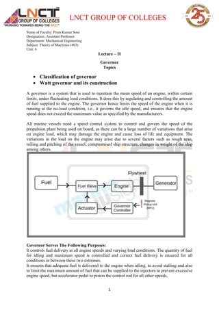
  • 1. LNCT GROUP OF COLLEGES Name of Faculty: Prem Kumar Soni Designation: Assistant Professor Department: Mechanical Engineering Subject: Theory of Machines (403) Unit: 6 1 Lecture – II Governor Topics  Classification of governor  Watt governor and its construction A governor is a system that is used to maintain the mean speed of an engine, within certain limits, under fluctuating load conditions. It does this by regulating and controlling the amount of fuel supplied to the engine. The governor hence limits the speed of the engine when it is running at the no-load condition, i.e., it governs the idle speed, and ensures that the engine speed does not exceed the maximum value as specified by the manufacturers. All marine vessels need a speed control system to control and govern the speed of the propulsion plant being used on board, as there can be a large number of variations that arise on engine load, which may damage the engine and cause loss of life and equipment. The variations in the load on the engine may arise due to several factors such as rough seas, rolling and pitching of the vessel, compromised ship structure, changes in weight of the ship among others. Governor Serves The Following Purposes: It controls fuel delivery at all engine speeds and varying load conditions. The quantity of fuel for idling and maximum speed is controlled and correct fuel delivery is ensured for all conditions in between these two extremes. It ensures that adequate fuel is delivered to the engine when idling, to avoid stalling and also to limit the maximum amount of fuel that can be supplied to the injectors to prevent excessive engine speed, but accelerator pedal to piston the control rod for all other speeds.
  • 2. LNCT GROUP OF COLLEGES Name of Faculty: Prem Kumar Soni Designation: Assistant Professor Department: Mechanical Engineering Subject: Theory of Machines (403) Unit: 6 2 Based on the source of controlling force, the governors can be classified into two types. Centrifugal Governors: In centrifugal governors, multiple masses know as governor balls, are responsible to revolve about the axis of a shaft, which is driven by suitable gearing from the engine crankshaft. Each ball is acted upon by a force which acts in the radially inward direction and is provided by dead weight, a spring or a combination of two. This force is commonly called as the controlling force and it will increase as the distance of the ball from the axis of rotation increases. The inward or outward movement of the ball is transmitted by the governor mechanism to the valve which controls the amount of energy supplied to the engine. Inertia Governor: In inertia governors, the balls are arranged in a manner that the inertia forces caused by angular acceleration or retardation of the governor shaft tend to change their position. The obvious advantage of inertia governor lies in its rapid response to the effect of a change of load. This advantage is small, however by the practical difficulty of arranging for the complete balance of the revolving parts of the governor. For this reason, Centrifugal governors are preferred over the inertia governors. ******** In a gasoline engine, the governor is usually placed between the carburetor and the intake manifold. Centrifugal governor is attached to the camshaft by a gear drive. The movement of the flywheel attached to the pivot arms of centrifugal governors is used to control the flow of gasoline in the carburetor, thus controlling the engine speed. Types of Governors Following are the three different types of governors used in automobile vehicle: 1. Mechanical or centrifugal governor. 2. Pneumatic governor. 3. Hydraulic governor. Mechanical or Centrifugal Governor Mechanical governors are fitted to large engines on an extension of the pump camshaft.
  • 3. LNCT GROUP OF COLLEGES Name of Faculty: Prem Kumar Soni Designation: Assistant Professor Department: Mechanical Engineering Subject: Theory of Machines (403) Unit: 6 3 Working of Mechanical Governor When the engine starts, the weights take up a position to maintain a stable idling speed. As the accelerator pedal is depressed against the spring, the weight moves inwards, and since the weight are linked to the control rod, the fuel delivery is increased and hence the engine speed also increases. The increased engine speed causes the pump camshaft to rotate faster, which moves the weights outward against the action of control springs, so reducing the fuel delivery until the correct balance is arrived at for a particular engine operating condition. Thus, the accelerator does not increase delivery directly but delays the action of the governor. The relative position of governor-weight and control-rod positions when the engine is at idling and full-load positions.
  • 4. LNCT GROUP OF COLLEGES Name of Faculty: Prem Kumar Soni Designation: Assistant Professor Department: Mechanical Engineering Subject: Theory of Machines (403) Unit: 6 4 Pneumatic Governor Pneumatic governors are most successfully used in small and medium-sized engines. They are sensitive to variations in torque loading and ensure stable idling control. As with pneumatic induction pipe control, the air supply at light loads is throttle by a butterfly valve placed in a choke. This valve is directly operated by the accelerator pedal. The throttle unit is placed between the air cleaner and the entry to the inlet manifold. Which results in the reduced air pressure at the end of induction? Injection then takes place into less dense air than with unrestricted induction, and the control thus becomes quantity rather than quality control. The fuel injection is controlled by the depression at the choke to a diaphragm chamber mounted on the end of the injection pump.
  • 5. LNCT GROUP OF COLLEGES Name of Faculty: Prem Kumar Soni Designation: Assistant Professor Department: Mechanical Engineering Subject: Theory of Machines (403) Unit: 6 5 The diaphragm plate is mounted on the end of the control rack of the pump. It is pushed to the full load position (to the right) by the main control spring. Again, the increased depression at the throttle, arising when the accelerator pedal is released. It will pull the diaphragm and control rod to the left, thus reducing the fuel supply. An auxiliary spring is also used to balance the height depression at idling speed. It is brought into action progressively by the action of a cam. Hydraulic Governor Hydraulic governors eliminate the high mechanical forces bearing loads and possible torsional vibrations in the drive. And, hence they are preferred over mechanical governors.
  • 6. LNCT GROUP OF COLLEGES Name of Faculty: Prem Kumar Soni Designation: Assistant Professor Department: Mechanical Engineering Subject: Theory of Machines (403) Unit: 6 6 In a mechanical governor, the operative agent is the centrifugal force which governs the speed. In a hydraulic governor, it is the pressure difference across an orifice required to pass the oil flow from a positive oil pump driven by an engine. The pressure difference varies as the square of the engine speed. And it is determined at equilibrium by the pressure of the driver’s foot on the accelerator pedal. A hydraulic governor, like a mechanical governor, is an all-speed governor i.e., the governor is in control throughout the whole rack is operated by the governor and not directly by the accelerator to the supply to maintain the speed, no matter what the power requirements may be from moment to moment. Watt Governor Watt governor is the simplest form of centrifugal governors. Centrifugal governors are special type of governors with a feedback system that controls the speed of an engine by regulating the flow of fuel or working fluid.
  • 7. LNCT GROUP OF COLLEGES Name of Faculty: Prem Kumar Soni Designation: Assistant Professor Department: Mechanical Engineering Subject: Theory of Machines (403) Unit: 6 7 Watt governor has two fly balls attached to two arms of negligible masses. Watt governor is used to supply the required amount of fuel at different speed. When the speed of engine increases, the supply of fuel needs to increase and as the engine speed decreases the supply of fuel should be decreased. So the fuel supply should be regulated according to the speed of the engine. With the help of watt governor we can obtain a required load on the engine with constant smooth function. Construction:- Watt governor consists of two fly balls which are located at the end of the arms. The upper parts of these two arms are pivoted to the spindle. This spindle is driven by the engine through the bevel gears. The lower parts of arms are connected to the sleeve which moves upward or downward as the balls moves upward or downward. The sleeve has stopper which are placed at up and down of sleeve to limit its movement. The sleeve is connected to throttle valve through bell crank lever . The movement of sleeve controls opening and closing of throttle valve. Working of Watt Governor Watt governors consist of two balls which are attached to both arms which are of negligible mass. The upper side of arms is pivoted so that its balls can move upwards and downwards. These arms are connected to the spindle . The engine drives the spindle through bevel gears.
  • 8. LNCT GROUP OF COLLEGES Name of Faculty: Prem Kumar Soni Designation: Assistant Professor Department: Mechanical Engineering Subject: Theory of Machines (403) Unit: 6 8 When the speed of the engine increases, the spindle rotates at high speed. The arms as well as the balls connected to spindle rotate at high speed. As the balls rotate at high speed and the upper side of arms are pivoted to the spindle, the balls moves in upward direction. The lower arms are connected to the sleeves. These sleeves are keyed to the spindle in such a way that it revolves with the spindle and can slide up and down according to the speed of rotation of spindle. As the engine speed increases and the balls move in upward direction, the sleeve connected to arms also moves upward and similarly moves downward when the speed of engine decreases. There are stoppers placed above and below the sleeve to limit the upward and downward motion of the sleeve. Now, there are two cases:- i) When engine speed increases. ii) When engine speed decreases. Let’s discuss these two cases. i) When the engine speed increases:- When the speed of engine increases, the load on the engine decreases and the speed of rotation of spindle increases. The centrifugal force on balls increases and the balls move upwards and hence the sleeve moves upward. As the sleeve moves upward. The upward movement of sleeve causes the throttle valve at the end of the ball crank lever to decrease the fuel supply. The power output is reduced. ii) When the engine speed decreases:- When the engine speed decreases, the load on engine increases and speed of rotation of spindle decrease. The centrifugal force on balls decreases and the balls moves downwards. As the balls move downwards, hence the sleeve moves downward which causes the throttle valve to increase the fuel supply and the power output is increased.
  • 9. LNCT GROUP OF COLLEGES Name of Faculty: Prem Kumar Soni Designation: Assistant Professor Department: Mechanical Engineering Subject: Theory of Machines (403) Unit: 6 9