Hyster d010 (s35 xm) forklift service repair manual
At21
1. Automatic Transmission Diagnosis - Course 273
1. Describe the function of the torque converter.
2. Identify the three major components of the torque converter that
contribute to the multiplication of torque.
3. Describe the operation of each major torque converter component.
4. Describe the operation of the lock−up mechanism of the torque
converter.
5. Identify the three major components of the simple planetary gear set.
6. Describe the function of the simple planetary gear set to provide
speed change, torque change and directional change.
7. Describe the operation of multi−plate clutches, brake bands and
one−way clutches.
8. Describe the effect of centrifugal fluid pressure on the operation of
a multi−plate clutch.
9. Given a clutch application chart and planetary gear model:
a. identify which holding devices are applied for each gear range.
b. identify the planetary gear components held for each gear range.
c. use a process of elimination to determine the proper function of
holding devices by testing it’s operation in another gear range.
d. use parallel holding devices to narrow diagnosis to faulty clutch
or brake.
10. Describe the difference between overdrive operation in the front
wheel drive and rear wheel drive automatic transmissions.
Section 1
Automatic Transmission Basics
Lesson Objectives
3. Automatic Transmission Basics
Automatic Transmission Diagnosis - Course 273
The torque converter provides an automatic means of coupling engine
torque to the input shaft of the transmission. The torque converter’s three
major components are; the pump impeller, the turbine runner and the
stator. The hydraulic fluid in the converter transfers torque through the
kinetic energy of the transmission fluid as it is forced from the impeller to
the turbine. The faster the engine rotates, the greater the torque applied
to the turbine. At low engine speeds, the turbine can be held stationary as
the force of the fluid’s kinetic energy is not great enough to overcome the
holding force of the light brake system application.
Torque Converter
Made of three major
components; the pump
impeller, turbine runner
and the stator.
The impeller is integrated with the torque converter case, with many
curved vanes evenly spaced and mounted inside. A guide ring is installed
on the inner edges of the vanes to provide a path for smooth fluid flow.
Torque
Converter - Impeller
The impeller rotates
whenever the engine is
running, causing the fluid
to flow outward toward
the turbine.
Torque
Converter
Components
Pump Impeller
4. Section 1
TOYOTA Technical Training
When the impeller is driven by the engine crankshaft, the fluid in the
impeller rotates with it. When the impeller speed increases, centrifugal
force causes the fluid to flow outward toward the turbine.
The turbine is located inside the converter case, but is not connected to
it. The input shaft of the transmission is attached by splines to the
turbine hub when the converter is mounted to the transmission. Many
cupped vanes are attached to the turbine. The curvature of the vanes is
opposite from that of the impeller vanes. Therefore, when the fluid is
thrust from the impeller, it is caught in the cupped vanes of the turbine
and torque is transferred to the transmission input shaft, turning it in
the same direction as the engine crankshaft. A guide ring similar to the
impeller is installed to the inner edge of the vanes.
Torque
Converter - Turbine
Fluid is caught in the
cupped vanes of the
turbine and torque is
transferred to the
input shaft.
The stator is located between the impeller and the turbine. It is
mounted on the stator reaction shaft which is fixed to the transmission
case. The vanes of the stator catch the fluid as it leaves the turbine
runner and redirects it so that it strikes the back of the vanes of the
impeller, giving the impeller added boost or torque. The benefit of this
added torque can be as great as 30% to 50%.
Turbine Runner
Stator
5. Automatic Transmission Basics
Automatic Transmission Diagnosis - Course 273
The one−way clutch mounted to the stator allows it to rotate in the
same direction as the engine crankshaft. However, if the stator
attempts to rotate in the opposite direction, the one−way clutch locks
the stator to prevent it from rotating. Therefore, the stator is rotated or
locked depending on the direction from which the fluid strikes against
the vanes.
Torque
Converter Stator
The vanes of the stator
catch the fluid as it
leaves the turbine and
redirects it back to the
impeller.
When the impeller is driven by the engine crankshaft, the fluid around
the impeller rotates in the same direction. As impeller speed increases,
centrifugal force causes the fluid to flow outward from the center of the
impeller and flows along the vane surfaces of the impeller. As speed
increases further, fluid is forced out away from the impeller toward the
turbine. The fluid strikes the vanes of the turbine causing it to rotate
in the same direction as the impeller.
After the fluid dissipates its energy against the vanes of the turbine, it
flows inward along the vanes of the turbine. When it reaches the
interior of the turbine, the turbine’s curved inner surface directs the
fluid at the vanes of the stator. Fluid strikes the curved vane of the
stator causing the one−way clutch to lock the stator and redirects fluid
at the impeller vanes in the direction of engine rotation, increasing
engine torque.
As the impeller and turbine approach the same speed, fluid strikes the
back of the stator vanes, releasing the one−way clutch and allows the
stator to freewheel. Unless the stator freewheels, being mounted to the
transmission body, fluid will strike the vanes of the stator and limit
engine rpm and upper engine performance.
Converter
Operation
6. Section 1
TOYOTA Technical Training
Stator Operation
The stator one-way
clutch locks the stator
counterclockwise and
freewheels clockwise.
At lower vehicle speeds the torque converter provides multiple gear
ratios when high torque is needed. As the impeller and the turbine
rotate at nearly the same speed, no torque multiplication is taking
place, the torque converter transmits the input torque from the engine
to the transmission at a ratio of almost 1:1. There is, however,
approximately 4% to 5% difference in rotational speed between the
turbine and impeller. The torque converter is not transmitting 100% of
the power generated by the engine to the transmission, so there is
energy loss.
To reduce energy loss and improve fuel economy, the lock−up clutch
mechanically connects the impeller and the turbine when the vehicle
speed is about 37 mph or higher. When the lock−up clutch is engaged,
100% of the power is transferred through the torque converter.
Converter
Lock-Up Clutch
7. Automatic Transmission Basics
Automatic Transmission Diagnosis - Course 273
Converter
Lock-Up Clutch
To reduce fuel consumption,
the lock-up clutch
engages the converter
case to lock the impeller
and the turbine.
The lock−up clutch is installed on the turbine hub between the turbine
and the converter front cover. Hydraulic pressure on either side of the
converter piston causes it to engage or disengage the converter front
cover. A set of dampening springs absorb the torsional force upon
clutch engagement to prevent shock transfer. The friction material
bonded to the lock−up piston is the same as that used on multiplate
clutch disks in the transmission.
When the lock−up clutch is engaged, it connects the impeller and
turbine. Engaging and disengaging the lock−up clutch is determined by
which side of the lock−up clutch the fluid enters the torque converter.
The difference in pressure on either side of the lock−up clutch
determines engagement or disengagement. Fluid can either enter the
body of the converter behind the lock−up clutch engaging the clutch, or
in front of the lock−up clutch to disengage it.
The fluid used to control the torque converter lock−up is also used to
remove heat from the converter and transfer it to the engine cooling
system through the heat exchanger in the radiator.
Lock-Up
Operation
8. Section 1
TOYOTA Technical Training
The operation of a simple planetary gear set is summarized in the
chart below. Different speeds and rotational directions can be obtained
by holding one of the planetary members in a fixed position, providing
input torque to another member, with the third member used as an
output member.
This chart represents more ratios and combinations than are used in
Toyota automatics, but are represented here to show the scope of its
design. The shaded areas represent the combinations used in Toyota
transmissions and are, therefore, the only combination we will discuss.
ÁÁÁÁ
ÁÁÁÁHELD
ÁÁÁÁÁ
ÁÁÁÁÁPOWER
ÁÁÁÁÁ
ÁÁÁÁÁPOWER
ÁÁÁÁÁÁÁÁ
ÁÁÁÁÁÁÁÁROTATIONAL ÁÁÁÁÁ
ÁÁÁÁÁROTATIONAL
ÁÁÁÁ
ÁÁÁÁ
HELD ÁÁÁÁÁ
ÁÁÁÁÁ
POWER
INPUT ÁÁÁÁÁ
ÁÁÁÁÁ
POWER
OUTPUT ÁÁÁÁ
ÁÁÁÁSPEED
ÁÁÁÁÁ
ÁÁÁÁÁTORQUE
ÁÁÁÁÁ
ÁÁÁÁÁ
ROTATIONAL
DIRECTION
Ring Gear
SunGear Carrier Reduced Increased
ÁÁÁÁÁ
ÁÁÁÁÁÁÁÁÁÁ
Same
direction
Ring GearÁÁÁÁÁ
ÁÁÁÁÁÁÁÁÁÁ
Carrier
ÁÁÁÁÁ
ÁÁÁÁÁÁÁÁÁÁ
Sun Gear
ÁÁÁÁ
ÁÁÁÁÁÁÁÁ
Increased
ÁÁÁÁÁ
ÁÁÁÁÁÁÁÁÁÁ
Reduced
ÁÁÁÁÁ
ÁÁÁÁÁÁÁÁÁÁ
direction
as drive
member
Sun Gear
Ring Gear Carrier Reduced Increased
ÁÁÁÁÁ
ÁÁÁÁÁ
ÁÁÁÁÁ
Same
direction
Sun Gear
Carrier Ring Gear Increased ReducedÁÁÁÁÁ
ÁÁÁÁÁ
direction
as drive
member
Carrier
Sun Gear Ring Gear Reduced Increased
ÁÁÁÁÁ
ÁÁÁÁÁ
ÁÁÁÁÁ
Opposite
direction
Carrier ÁÁÁÁÁ
ÁÁÁÁÁÁÁÁÁÁ
Ring Gear
ÁÁÁÁÁ
ÁÁÁÁÁÁÁÁÁÁ
Sun Gear
ÁÁÁÁ
ÁÁÁÁÁÁÁÁ
Increased
ÁÁÁÁÁ
ÁÁÁÁÁÁÁÁÁÁ
Reduced
ÁÁÁÁÁ
ÁÁÁÁÁÁÁÁÁÁ
from drive
member
When the ring gear or sun gear is held in a fixed position and either of
the other members is an input member, the output gear rotational
direction is always the same as the input gear rotational direction.
When the internal teeth of the ring gear turns clockwise, the external
teeth of the pinion gears walk around the fixed sun gear while rotating
clockwise. This causes the carrier to rotate at a reduced speed.
Simple
Planetary Gear
Simple Planetary
Gear Operation
The shaded area
represents the
combinations used in
Toyota transmissions.
Forward
Direction
Reduction
9. Automatic Transmission Basics
Automatic Transmission Diagnosis - Course 273
Reduction
Example: Speed
reduction - torque
increase
When the carrier turns clockwise, the external toothed pinion gears
walk around the external toothed sun gear while rotating clockwise.
The pinion gears cause the internal toothed ring gear to accelerate to a
speed greater than the carrier speed in a clockwise direction.
Overdrive
Example: Speed
increase - torque
reduction
Overdrive
10. Section 1
TOYOTA Technical Training
Whenever the carrier is held and either of the other gears are input
members, the output gear will rotate in the opposite direction.
With the carrier held, when the external toothed sun gear turns
clockwise, the external toothed pinion gears on the carrier idle in place
and drive the internal toothed ring gear in the opposite direction.
Reverse
Example: Speed
reduction - torque
increase
When any two members are held together and another member
provides the input turning force, the entire assembly turns at the same
speed as the input member.
Now the gear ratios from a single planetary set do not give us the
desired ratios which take advantage of the optimum torque curve of the
engine. So it is necessary to use two single planetary gear sets. This
design is basic to most all automatic transmissions in production today.
Reverse
Direction
Direct Drive
(One-To-One
Ratio)
11. Automatic Transmission Basics
Automatic Transmission Diagnosis - Course 273
There are three types of holding devices used in the planetary gear set.
Each type has its specific design advantage. The three include
multiplate clutches/brakes, brake bands and one−way clutches.
• Multiplate Clutch Ċ holds two rotating planetary components.
• Roller or Sprag One−Way Clutch Ċ holds planetary components in
one rotational direction and freewheels in the other direction.
• Multiplate Brake and Brake Band Ċ holds planetary components
to the transmission case.
The multiplate clutch and multiplate brake are the most common of
the three types of holding devices; they are versatile and can be
modified easily by removing or including more friction discs. The brake
band takes very little space in the cavity of the transmission housing
and has a large surface area to create strong holding force. One−way
clutches are small in size and release and apply quickly, giving good
response for upshifts and downshifts.
Multiplate Clutch
The multiplate clutch
connects two rotating
components of the
planetary gear set.
The multiplate clutch connects two rotating components of the
planetary gear set. The Simpson planetary gear unit uses two
multiplate clutches, the forward clutch (C1) and the direct clutch (C2).
Each clutch drum is slotted on the inner diameter to engage the steel
plates and transfer turning torque from the engine. The drum also
provides the bore for the clutch piston.
Holding
Devices For
Planetary Gear
Set
Multiplate Clutch
12. Section 1
TOYOTA Technical Training
Friction discs are steel plates which have friction material bonded to
them. They are always located between two steel plates. The friction
disc inner diameter is slotted to fit over the splines of the clutch hub.
Steel plates are slotted on the outer diameter to fit the slots of the
clutch drum or transmission case. They provide a smooth surface for
the friction discs to engage with. Steel plates can be installed next to
one another to give a specific clearance for the clutch pack.
Because this assembly rotates while the vehicle is in motion, it
presents a unique challenge to ensure pressurized fluid reaches the
clutch and holds the clutch engaged for many tens of thousands of
miles of service. Oil seal rings seal the fluid passage between the clutch
drum and oil pump stator support and transmission center support.
Seals are mounted on the piston inner and outer diameter which seal
the fluid applying the piston. A relief ball valve is housed in the piston
body to release hydraulic fluid when the clutch is released. As the
drum rotates, some fluid remains behind the piston and centrifugal
force causes the fluid to flow to the outer diameter of the drum causing
pressure. This pressure may not fully engage the clutch, however, it
may reduce the clearance between the discs and metal plates,
promoting heat and wear.
The relief ball valve is designed to allow fluid to escape when pressure
is released. As pressure drops, centrifugal force causes the ball to move
away from the valve seat, allowing fluid to escape so the piston can be
seated, providing proper clearance between the disc and steel plates.
Multiplate
Clutch Operation
Hydraulic
pressure applies the
clutch, and the return
springs release it.
Multiplate
Operation
13. Automatic Transmission Basics
Automatic Transmission Diagnosis - Course 273
The U−series transmissions first introduced in the 2000 Echo and
Celica, utilizes centrifugal fluid pressure to cancel the effect of
centrifugal force on the piston when pressure is released in the clutch.
Fluid used for lubrication is caught between the clutch spring retainer
and the clutch piston. As the clutch drum rotates, fluid in the canceling
fluid pressure chamber counters the pressure built up inside the drum
pressure chamber, canceling the pressure build−up.
Centrifugal Fluid
Pressure Canceling
As the clutch drum
rotates, fluid in the
canceling fluid pressure
chamber, counters the
pressure built up inside
the drum pressure
chamber, and counteracts
the pressure build-up.
A one−way clutch is a holding device which requires no seals or
hydraulic pressure to apply. They are either a roller clutch or sprag
clutch. Their operation is similar in that they both rely on wedging the
metal sprags between two races. Two one−way clutches are used in the
Simpson Planetary Gear Set. The No. 1 one−way clutch (F1) is used in
second gear and the No. 2 one−way clutch (F2) is used in first gear.
U-Series
Transmission
Counter
Centrifugal Force
One-Way Clutch
14. Section 1
TOYOTA Technical Training
A one−way sprag clutch consists of a hub as an inner race and a drum,
or outer race. The two races are separated by a number of sprags which
look like a figure 8" when looking at them from the side view. In the
illustration in figure 1−14, the side view of the sprag shows four lobes.
The two lobes identified by L1 are shorter than the distance between
the two races. The opposite lobes are longer than the distance between
the races. As a result, when the center race turns clockwise, it causes
the sprag to tilt and the short distance allows the race to turn.
One-Way Clutch
When the center race
turns counterclockwise, it
tries to move the sprag
so that the long distance
is wedged against the
outer race.
When the center race turns counterclockwise, it tries to move the sprag
so that the long distance is wedged against the outer race. This causes
the center race to stop turning. To assist the sprags in their wedging
action, a retainer spring is installed which keeps the sprags slightly
tilted at all times in the direction which will lock the turning race.
Although the sprag clutch is used most often in Toyota automatics, a
second design can be found in the U−series transmission and other
transmission models. A one−way roller clutch consists of a hub, rollers,
and springs surrounded by a cam−cut drum. The cam−cut is in the
shape of a wedge, smaller on one end than the other. The spring pushes
the rollers toward the narrow end of the wedge. When the inner race
rotates in the counterclockwise direction, the rollers compress the
spring and the race is allowed to turn. If the race is rotated in the
opposite direction, it forces the rollers into the narrow end of the cam
cut and locks the race.
15. Automatic Transmission Basics
Automatic Transmission Diagnosis - Course 273
One-Way
Roller Clutch
When the inner race is
rotated in the clockwise
direction, it forces the
rollers into the narrow
end of the wedge and
locks the race.
The No. 1 one−way clutch (F1) operates with the second brake (B2) to
prevent the sun gear from turning counterclockwise. The No. 2 one−way
clutch (F2) prevents the rear planetary carrier from turning
counterclockwise.
No. 1 and No. 2
One-Way Clutch
F1 operates with the
second brake (B2) to
hold the sun gear from
turning counterclockwise.
F2 prevents the rear
planetary carrier from
turning counterclockwise.
16. Section 1
TOYOTA Technical Training
There are two types of brakes; the wet multiplate type and the band
type. The multiplate type is used on the overdrive brake (B0), second
coast brake (B1), second brake (B2), and the first and reverse brake
(B3).
The multiplate brake is constructed in a similar manner to the
multiplate clutch. It locks or holds a rotating component of the
planetary gear set to the case of the transmission.
Hydraulic pressure actuates the piston and return springs return the
piston to the rest position in the clutch drum when pressure is
released. Friction discs are steel plates to which friction material is
bonded. They are always located between two steel plates. The friction
disc inner diameter is slotted to fit over the splines of the clutch hub,
similar to the multiplate clutch; however, the steel plates spline to the
transmission case, thus providing an anchor.
Multiplate Brake
The multiplate brake
locks a planetary gear
component to the case of
the transmission.
Brakes
Multiplate Brakes
17. Automatic Transmission Basics
Automatic Transmission Diagnosis - Course 273
The brake band performs the same functions as the multiplate brake
and is located around the outer circumference of the direct clutch
drum. One end of this brake band is anchored to the transmission case
with a pin, while the other end contacts the brake piston rod which is
controlled by hydraulic pressure and spring tension.
Band Type Brake
The brake band locks a
planetary gear
component to the case of
the transmission.
Brake Band
18. Section 1
TOYOTA Technical Training
Band Operation
The inner spring transfers
motion from the
piston to the piston rod,
applying pressure to the
end of the brake band.
The band is applied by a piston and piston rod located in the
transmission case. When hydraulic pressure is applied to the piston,
the piston moves to the left compressing the outer spring. The inner
spring transfers motion from the piston to the piston rod, applying
pressure to the end of the brake band. As the inner spring compresses,
the piston comes in direct contact with the piston rod shoulder and a
high frictional force is generated between the brake band and drum.
The brake band clamps down on the drum which causes the drum and
a member of the planetary gear set to be held to the transmission case.
When the pressurized fluid is drained from the cylinder, the piston and
piston rod are pushed back by the force of the outer spring so the drum
is released by the brake band.
Band Operation
19. Automatic Transmission Basics
Automatic Transmission Diagnosis - Course 273
The planetary gear set cutaway and model shown below are found in
Toyota Repair Manuals and New Car Features Books. The model will
help you visualize the workings of the holding devices, gear shafts and
planetary gear members for all gear positions.
There are three shafts in the Simpson planetary: the input shaft, sun
gear, and the output shaft. The input shaft is driven from the turbine
in the torque converter. It is connected to the front planetary ring gear
through the multiplate clutches. The sun gear, which is common to
both the front and rear planetary gear sets, transfers torque from the
front planetary set to the rear planetary set. The output shaft is
splined to the carrier of the front planetary gear set and to the ring
gear of the rear planetary and then provides turning torque to the rear
wheels or the overdrive unit.
The output shaft, for the purposes of power flow, refers to the output of
the Simpson planetary gear set. It may be referred to as the
intermediate shaft in other references. However, for our purposes in
discussing power flow, it will be referred to as the output shaft.
Planetary
Gear Shafts
The planetary gear set
cutaway and model will
help visualize the
workings of holding
devices, gear shafts, and
planetary gear member.
Power Flow
Model
Gear Train Shafts
20. Section 1
TOYOTA Technical Training
Multiplate clutches and brakes were discussed in detail earlier, and in
the cutaway model on the next page, we can identify their position and
the components to which they are connected. The holding devices for
the Simpson planetary gear set are identified below with the
components they control:
ÁÁÁÁÁÁÁÁÁÁÁÁÁÁÁÁHolding Device
ÁÁÁÁÁÁÁÁÁÁÁÁÁÁÁÁÁÁÁÁÁÁÁÁÁÁÁÁÁÁÁÁFunction
ÁÁÁÁC0
ÁÁÁÁÁÁÁÁÁÁÁÁÁÁO/D Direct Clutch
ÁÁÁÁÁÁÁÁÁÁÁÁÁÁÁÁÁÁÁÁÁÁÁÁÁÁÁÁÁÁÁÁConnects overdrive sun gear and overdrive carrier.
ÁÁÁÁ
ÁÁ
B0
ÁÁÁÁÁÁÁÁÁÁÁÁÁÁ
ÁÁÁÁÁÁÁ
O/D Brake
ÁÁÁÁÁÁÁÁÁÁÁÁÁÁÁÁÁÁÁÁÁÁÁÁÁÁÁÁÁÁÁÁ
ÁÁÁÁÁÁÁÁÁÁÁÁÁÁÁÁ
Prevents overdrive sun gear from turning either clockwise or
counterclockwise.
ÁÁ
ÁÁÁÁ
F0ÁÁÁÁÁÁÁ
ÁÁÁÁÁÁÁÁÁÁÁÁÁÁ
O/D One-Way Clutch ÁÁÁÁÁÁÁÁÁÁÁÁÁÁÁÁ
ÁÁÁÁÁÁÁÁÁÁÁÁÁÁÁÁÁÁÁÁÁÁÁÁÁÁÁÁÁÁÁÁ
When transmission is being driven by engine, connects
overdrive sun gear and overdrive carrier.
ÁÁ
ÁÁ
C1ÁÁÁÁÁÁÁ
ÁÁÁÁÁÁÁ
Forward Clutch ÁÁÁÁÁÁÁÁÁÁÁÁÁÁÁÁ
ÁÁÁÁÁÁÁÁÁÁÁÁÁÁÁÁ
Connects input shaft and front planetary ring gear.
ÁÁ
ÁÁC2ÁÁÁÁÁÁÁ
ÁÁÁÁÁÁÁDirect Clutch ÁÁÁÁÁÁÁÁÁÁÁÁÁÁÁÁ
ÁÁÁÁÁÁÁÁÁÁÁÁÁÁÁÁConnects input shaft and front and rear planetary sun gear.
ÁÁ
ÁÁ
ÁÁ
B1ÁÁÁÁÁÁÁ
ÁÁÁÁÁÁÁ
ÁÁÁÁÁÁÁ
2nd Coast Brake ÁÁÁÁÁÁÁÁÁÁÁÁÁÁÁÁ
ÁÁÁÁÁÁÁÁÁÁÁÁÁÁÁÁ
ÁÁÁÁÁÁÁÁÁÁÁÁÁÁÁÁ
Prevents front and rear planetary sun gear from turning either
clockwise or counterclockwise.
ÁÁ
ÁÁÁÁ
B2ÁÁÁÁÁÁÁ
ÁÁÁÁÁÁÁÁÁÁÁÁÁÁ
2nd Brake ÁÁÁÁÁÁÁÁÁÁÁÁÁÁÁÁ
ÁÁÁÁÁÁÁÁÁÁÁÁÁÁÁÁÁÁÁÁÁÁÁÁÁÁÁÁÁÁÁÁ
Prevents outer race of F1 from turning either clockwise or
counterclockwise, thus preventing front and rear planetary sun
gear from turning counterclockwise.
ÁÁ
ÁÁÁÁ
B3ÁÁÁÁÁÁÁ
ÁÁÁÁÁÁÁÁÁÁÁÁÁÁ
1st and Reverse BrakeÁÁÁÁÁÁÁÁÁÁÁÁÁÁÁÁ
ÁÁÁÁÁÁÁÁÁÁÁÁÁÁÁÁÁÁÁÁÁÁÁÁÁÁÁÁÁÁÁÁ
Prevents rear planetary carrier from turning either clockwise or
counter clockwise.
ÁÁ
ÁÁ
F1ÁÁÁÁÁÁÁ
ÁÁÁÁÁÁÁ
No. 1 One-Way ClutchÁÁÁÁÁÁÁÁÁÁÁÁÁÁÁÁ
ÁÁÁÁÁÁÁÁÁÁÁÁÁÁÁÁ
When B2 is operating, prevents front and rear planetary sun
gear from turning counterclockwise.
ÁÁ
ÁÁF2
ÁÁÁÁÁÁÁ
ÁÁÁÁÁÁÁNo. 2 One-Way Clutch
ÁÁÁÁÁÁÁÁÁÁÁÁÁÁÁÁ
ÁÁÁÁÁÁÁÁÁÁÁÁÁÁÁÁPrevents rear planetary carrier from turning counterclockwise.
The value of this model can be appreciated when observing the control
of the rear carrier and the sun gear. The first and reverse brake (B3)
and the No. 2 one−way clutch (F2) control the rear carrier in parallel.
Together they provide a great holding force on the carrier to prevent it
from turning during low first gear.
Holding Devices
Function of
Holding Devices
Each holding device and
the component it controls
is identified in this chart.
21. Automatic Transmission Basics
Automatic Transmission Diagnosis - Course 273
The second brake (B2) and the No. 1 one−way clutch (F1) control the
sun gear in series. This allows the sun gear to turn clockwise only
when B2 is applied
The second coast brake (B1) holds the sun gear, preventing it from
turning in either direction. This feature provides for engine braking on
deceleration while in 2−range second gear.
Planetary
Holding Devices
The first and reverse
brake (B3) and No. 2
one-way clutch (F2) both
hold the rear planetary
carrier.
The second brake (B2)
and the No. 1 one-way
clutch (F1) work together
to hold the sun gear.
The second coast
brake (B1) holds the sun
gear also.
22. Section 1
TOYOTA Technical Training
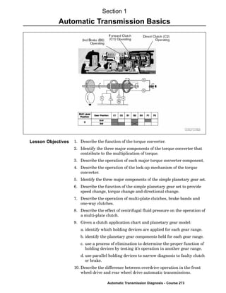
The gear position in which these holding devices are applied can be
found on the clutch application chart below. The chart describes which
holding devices are applied for a given gear position. If you follow down
the left side of the chart to shift lever position D" and first" gear
position, the shaded boxes to the right of the gear position indicate the
holding devices used in drive first gear. At the top of the column above
the shaded box you will find the code designation for the holding
device. For example, in drive first gear, the forward clutch (C1) and the
No. 2 one−way clutch (F2) are applied to achieve first gear. The clutch
Clutch Application
Chart for A130
Transmission
The chart describes
which holding devices
are applied for a given
gear position.
application chart shows that as the transmission upshifts to the next
gear, an additional holding device is engaged in addition to those
clutches and brakes already applied. For example, when upshifting to
second gear, B2 is applied while C1 remains applied; and when
upshifting to third gear, C2 is applied while B2 and C1 remain applied.
The one way clutches are the only holding devices to release as an
upshift occurs, but they remain ready to automatically apply when the
rotating member turns in a counterclockwise direction.
This stacking feature allows the transmission to remain in the lower
gear when a clutch/brake fails to engage on an upshift and also
provides a downshift by simply disengaging one clutch.
The clutch application chart is your key to diagnosis. When a
transmission malfunction occurs and the diagnosis leads you to a specific
gear, you can refer to this chart to pinpoint the faulty holding device.
When the holding device you suspect is used in another gear position, you
should be able to detect a failure in that gear position also while either
Three Speed
Clutch
Application
Chart
23. Automatic Transmission Basics
Automatic Transmission Diagnosis - Course 273
accelerating or decelerating. If that gear position does not exhibit a
problem, look for another device shared with another gear position and
look for a malfunction to occur. Using a process of elimination, you can
pinpoint the holding device which is causing the malfunction.
First gear is unique because it uses both the front and rear planetary gear
sets. The forward clutch (C1) is applied in all forward gears and drives the
ring gear of the front planetary gear set. When the ring gear rotates
clockwise, it causes the pinions to rotate clockwise since the sun gear is not
held to the case. The sun gear rotates in a counterclockwise direction. The
front planetary carrier, which is connected to the output shaft, rotates, but
more slowly than the ring gear; so for practical purposes, it is the held unit.
In the rear planetary gear set, the carrier is locked to the case by the No.
2 one−way clutch (F2). Turning torque is transferred to the rear planetary
by the sun gear, which is turning counterclockwise. With the carrier held,
the planetary gears rotate in a clockwise direction and cause the rear
planetary ring gear to turn clockwise. The rear planetary ring gear is
connected to the output shaft and transfers torque to the drive wheels.
D or
2-Range First Gear
First gear is unique
because it uses both the
front and rear planetary
gear sets.
Power Flow
Through
Simpson
Planetary Gear
Set - D or
2-Range
First Gear
24. Section 1
TOYOTA Technical Training
The forward clutch (C1) connects the input shaft to the front planetary
ring gear. The sun gear is driven in a counterclockwise direction in first
gear and by simply applying the second brake (B2) the sun gear is
stopped by the No. 1 one−way clutch (F1) and held to the case. When
the sun gear is held, the front pinion gears driven by the ring gear
walks around the sun gear and the carrier turns the output shaft.
The advantage of the No. 2 one−way clutch (F2) is in the automatic
upshift and downshift. Only one multiplate clutch is applied or
released to achieve an upshift to second gear or downshift to first gear.
Notice how the second brake (B2) and the one−way clutch (F1) both hold
the sun gear in series. The second brake holds the outer race of the
one−way clutch to the transmission case when applied. The one−way
clutch prevents the sun gear from rotating counterclockwise only when
the second brake is applied.
D-Range
Second Gear
Second gear uses the
front planetary gear set
only.
D-Range Second
Gear
25. Automatic Transmission Basics
Automatic Transmission Diagnosis - Course 273
The forward clutch (C1) is applied in all forward gears and connects the
input shaft to the front planetary ring gear as it does in all forward
gears. The direct clutch (C2) connects the input shaft to the common sun
gear. By applying both the direct clutch and the forward clutch, we have
locked the ring gear and the sun gear to each other through the direct
clutch drum and the input sun gear drum. Whenever two members of
the planetary gear set are locked together direct drive is the result.
Notice that the second brake (B2) is also applied in third gear; however,
since the No. 1 one−way clutch (F1) does not hold the sun gear in the
clockwise direction, the second brake has no effect in third gear. So why is
it applied in third gear? The reason lies in a downshift to second gear. All
that is necessary for a downshift to second gear is to release the direct
clutch (C2). The ring gear provides input torque and the sun gear is
released. The carrier is connected to the output shaft and final drive so
the output shaft tends to slow the carrier. The pinion gears rotate
clockwise turning the sun gear counterclockwise until it is stopped by the
No. 1 one−way clutch. The carrier provides the output to the final drive.
D-Range Third Gear
Third gear uses the front
planetary gear set only.
D-Range Third
Gear
26. Section 1
TOYOTA Technical Training
The direct clutch (C2) is applied in reverse, which connects the input
shaft to the sun gear. The first and reverse brake (B3) is also applied,
locking the rear carrier to the case. With the carrier locked in position,
the sun gear turning in the clockwise direction causes the planetary
gears to rotate counterclockwise. The planetary gears will then drive
the ring gear and the output shaft counterclockwise.
Up to this point we have examined reverse gear and those forward gear
positions which are automatic. That is, with the gear selector in
D−position all forward gears are upshifted automatically. The gears can
also be selected manually, utilizing additional holding devices. This
feature not only provides additional characteristics to the drivetrain
but also allows a means of diagnosis for faults in certain holding
devices.
Reverse Range
Reverse gear uses the
rear planetary gear set
only.
Reverse Range
27. Automatic Transmission Basics
Automatic Transmission Diagnosis - Course 273
When the gear selector is placed in the L−position, the first and reverse
brake (B3) is applied through the position of the manual valve. The
first and reverse brake performs the same function as the No. 2 one−way
clutch (F2) does in the forward direction. When the first and reverse
brake (B3) is applied it holds the rear planetary gear carrier from
turning in either direction, whereas the No. 2 one−way clutch holds the
carrier in the counterclockwise direction only.
The advantage that the first and reverse brake has, is that engine
braking can be achieved to slow the vehicle on deceleration. In D1,"
only the No. 2 one−way clutch holds the carrier, so while decelerating,
the one−way clutch would release and no engine braking would occur.
First Gear Model
The rear planetary carrier
cannot rotate in either
direction
The rear planetary carrier is
held counterclockwise only
and freewheels in the
clockwise direction
Comparison of
D and L-Range
First Gear
28. Section 1
TOYOTA Technical Training
When the gear selector is placed in the 2−position, the second coast
brake (B1) is applied by way of the manual valve. When the second
coast brake is applied, it holds the sun gear from rotating in either
direction. Power flow is the same with the selector in 2," as when the
selector is in D" because the second coast brake is parallel to the
second brake and No. 1 one−way clutch.
However, when the transmission is being driven by the wheels on
deceleration, the force from the output shaft is transmitted to the front
carrier, causing the front planetary pinion gears to revolve clockwise
around the sun gear. Since the sun gear is held by the second coast
brake, the planetary gears walk around the sun clockwise and drive the
front planetary ring gear clockwise through the input shaft and torque
converter to the crankshaft for engine braking. In contrast, while in
second gear with the selector in D−position, the sun gear is held in the
counterclockwise direction only and the sun gear rotates in a clockwise
direction and there is no engine braking.
The advantage that 2−range has over D2" is that the engine can be
used to slow the vehicle on deceleration, and this feature can be used to
aid in diagnosis. For example, a transmission which does not have
second gear in D−position but does have second gear while manually
shifting can be narrowed to the second brake (B2) or No. 1 one−way
clutch (F1). These components and related hydraulic circuits become
the primary focus in our diagnosis.
Comparison of
D2 and 2-Range
Second Gear
29. Automatic Transmission Basics
Automatic Transmission Diagnosis - Course 273
Second Gear Model
The sun gear cannot
rotate in either direction.
The sun gear is held in
the counterclockwise
direction only in a
clockwise direction.
30. Section 1
TOYOTA Technical Training
One simple planetary gear set is added to the 3−speed automatic
transmission to make it a 4−speed automatic transmission (three
speeds forward and one overdrive). This additional gear set can be
added in front of or behind the Simpson Planetary Gear Set to
accomplish overdrive. When the vehicle is driving in overdrive gear,
the speed of the output shaft is greater than that of the input shaft.
O/D Planetary Units
This simple planetary gear set can be in
front of the Simpson planetary gear set or
behind it.
Power Flow
Through
O/D Unit
31. Automatic Transmission Basics
Automatic Transmission Diagnosis - Course 273
The clutch application chart is similar to the one seen earlier while
discussing power flow through the Simpson planetary gear set,
however, three additional holding devices for overdrive have been
added. The overdrive direct clutch (C0) and the overdrive one−way
clutch (F0) are applied in reverse and forward gears through third
gear. In overdrive, the overdrive brake (B0) is applied and the overdrive
direct clutch (C0) is released.
Four Speed Clutch
Application Chart
Three additional holding devices are
required for overdrive
Overdrive is designed to operate at vehicle speed above 25 mph in
order to reduce the required engine speed when the vehicle is operating
under a light load. Power is input through the overdrive planetary
carrier and output from the overdrive ring gear. The operation of
holding devices and planetary members in the forward direction is the
same whether it is a front wheel drive or rear wheel drive vehicle. In
reverse, however, the overdrive one−way clutch (F0) in the front wheel
drive transmission does not hold.
The direction of rotation in the front−mounted O/D unit is always
clockwise. The direction of rotation in the rear−mounted O/D units is
Four Speed
Clutch Application
Chart
O/D Operation
32. Section 1
TOYOTA Technical Training
mostly clockwise, with the exception of reverse, in which case the
intermediate shaft rotates counterclockwise. When the input torque
comes into the overdrive unit in a counterclockwise direction, the
overdrive one−way clutch (F0) free−wheels. Therefore, when a vehicle
with the rear−mounted O/D unit is placed in reverse, the overdrive
direct clutch (C0) is the only unit holding the O/D unit in direct drive.
For this reason, when the overdrive direct clutch fails, the vehicle will
go forward but will not go in reverse and there is no engine braking in
low or D2.
O/D Planetary Gear Unit
Power is input through the overdrive
planetary carrier and output from the
overdrive ring gear.
33. Automatic Transmission Basics
Automatic Transmission Diagnosis - Course 273
The overdrive planetary unit is in direct drive (1:1 gear ratio) for
reverse and all forward gears except overdrive. In direct drive the
overdrive direct clutch (C0) and overdrive one−way clutch (F0) are both
applied locking the sun gear to the carrier. With the sun gear and
carrier locked together, the ring gear rotates with the carrier and the
O/D assembly rotates as one unit.
Direct Drive
The overdrive planetary
unit is in direct drive for
reverse and all forward
gears except overdrive.
Direct Drive
(Not in Overdrive)
34. Section 1
TOYOTA Technical Training
In overdrive, the overdrive brake (B0) locks the O/D sun gear, so when
the overdrive carrier rotates clockwise, the overdrive pinion gears
revolve clockwise around the sun gear, carrying the overdrive ring gear
clockwise at a speed faster than the overdrive carrier.
Overdrive
The overdrive ring gear
rotates clockwise at a
speed faster than the
overdrive carrier.
Overdrive