Downloaded 259 times

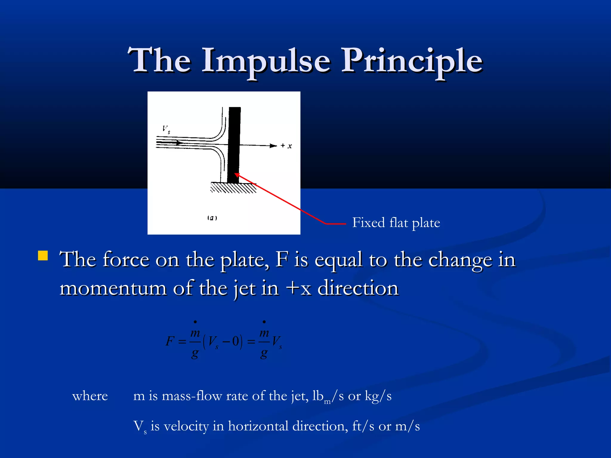


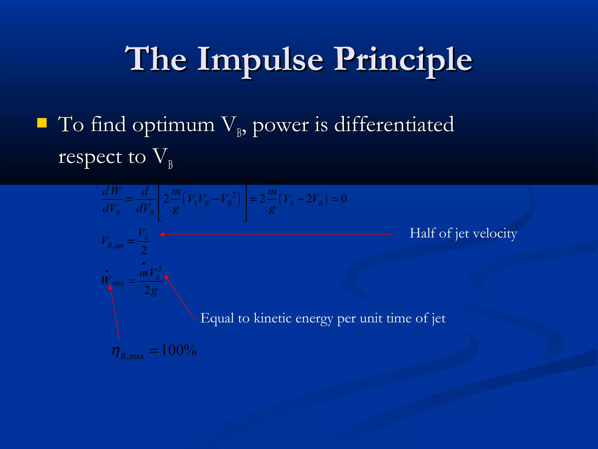

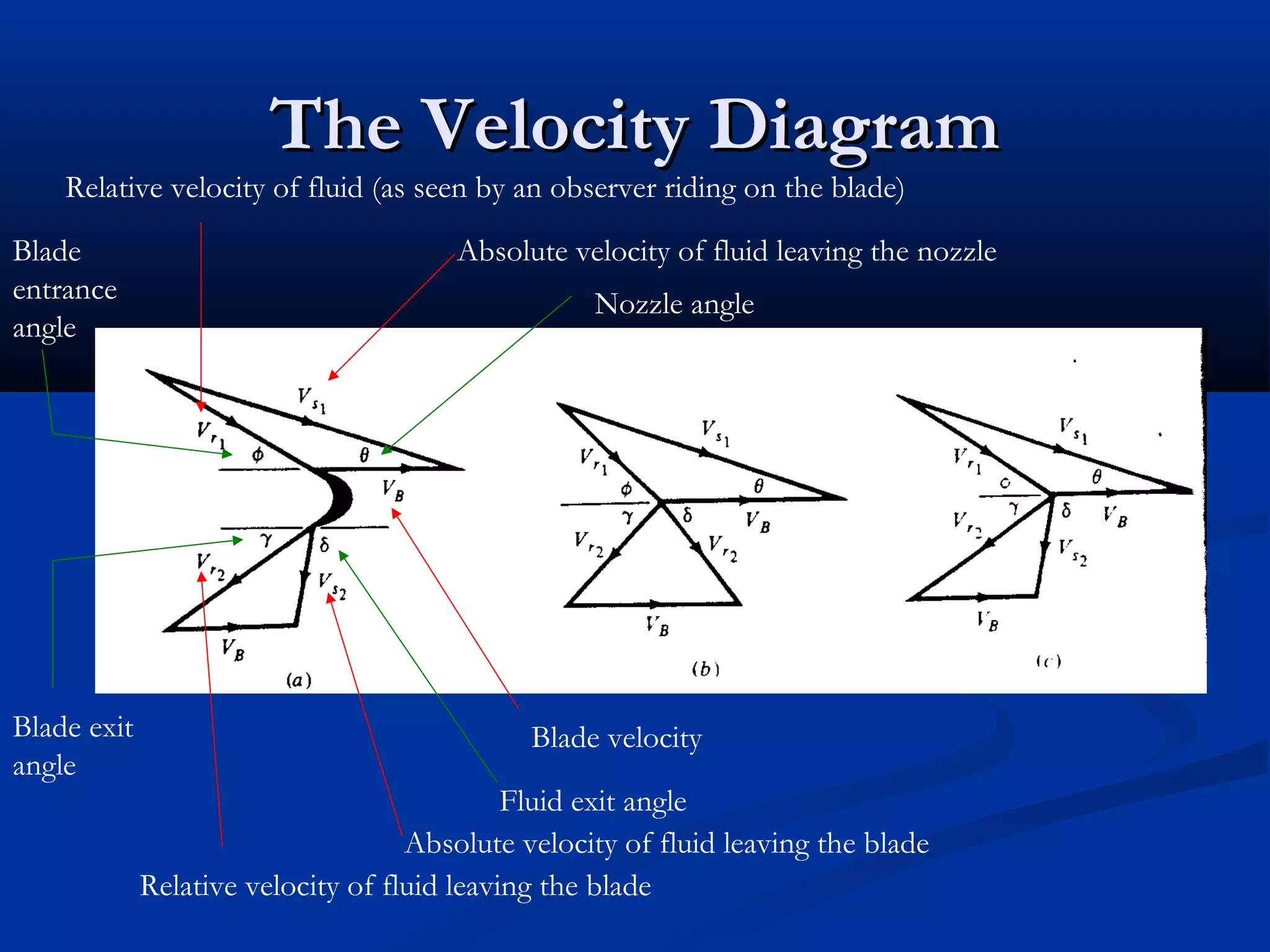


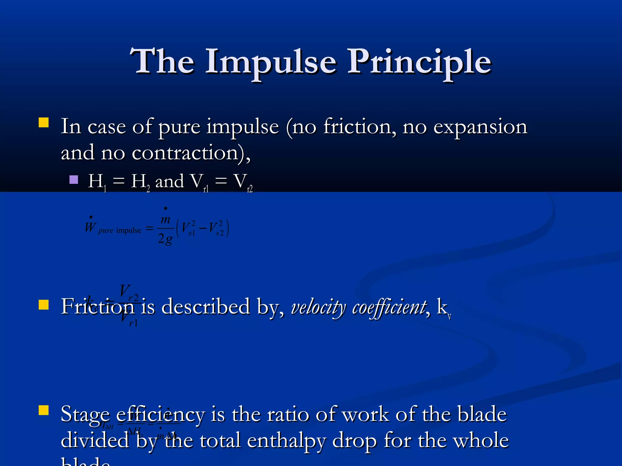
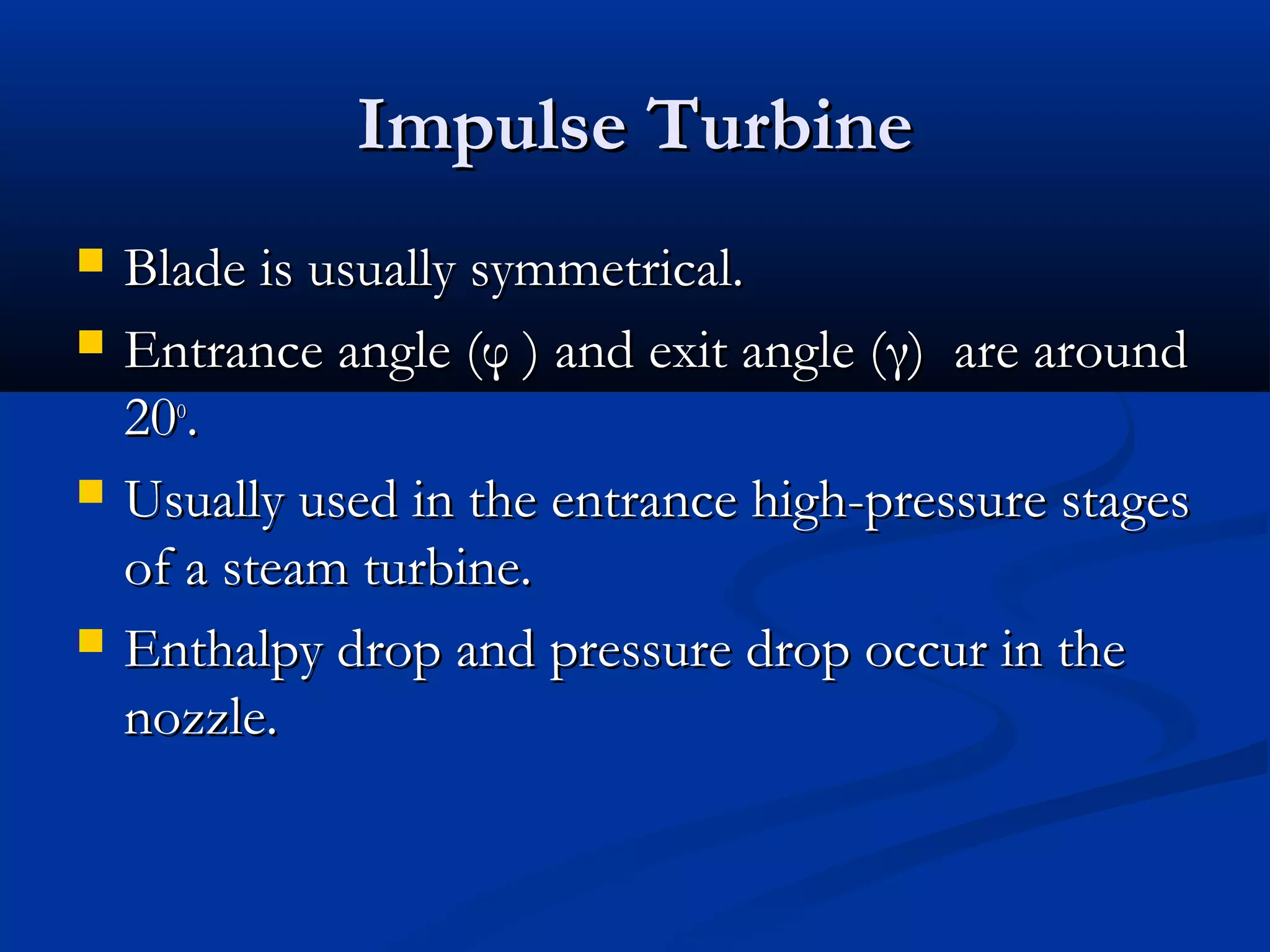


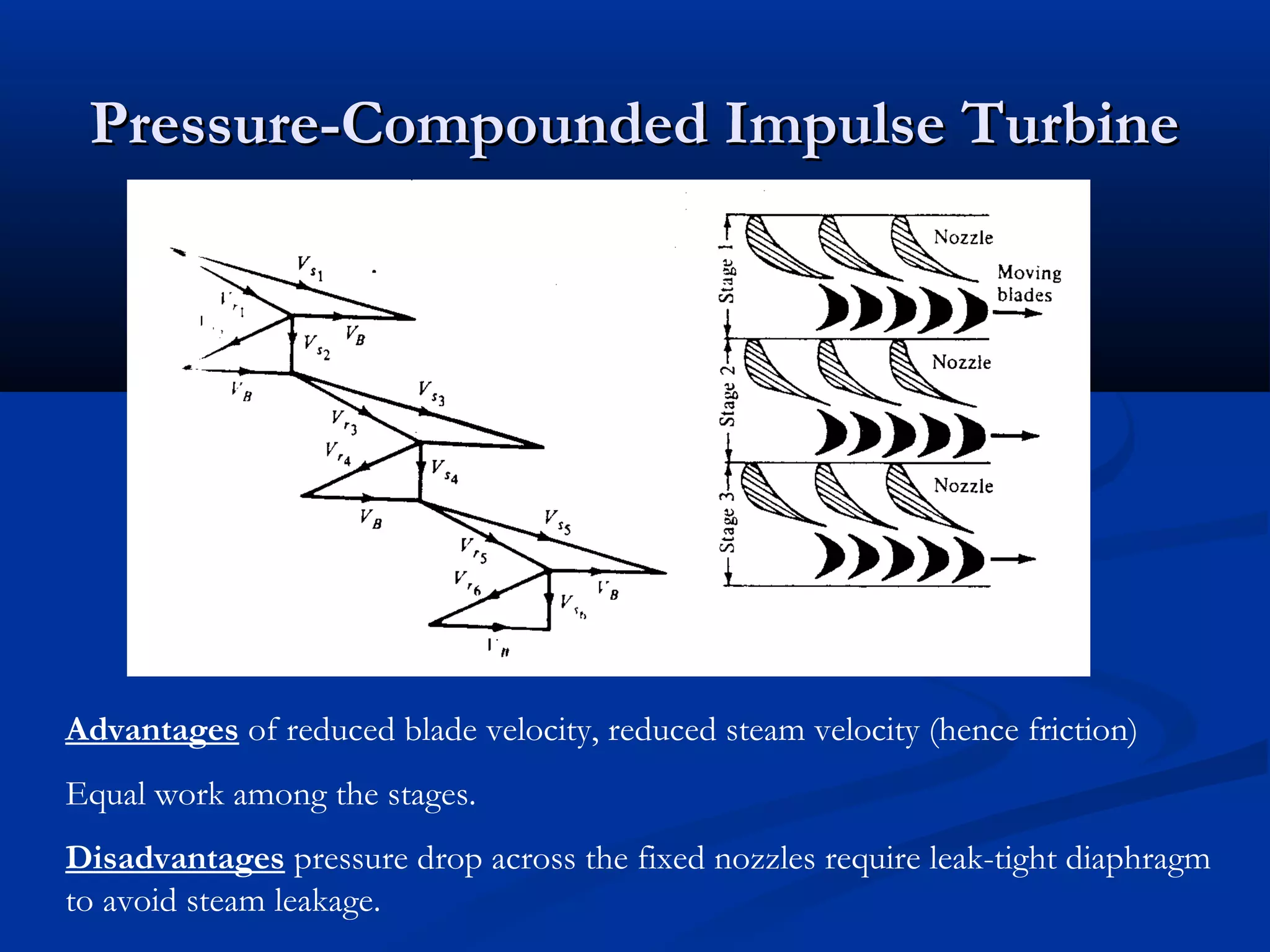


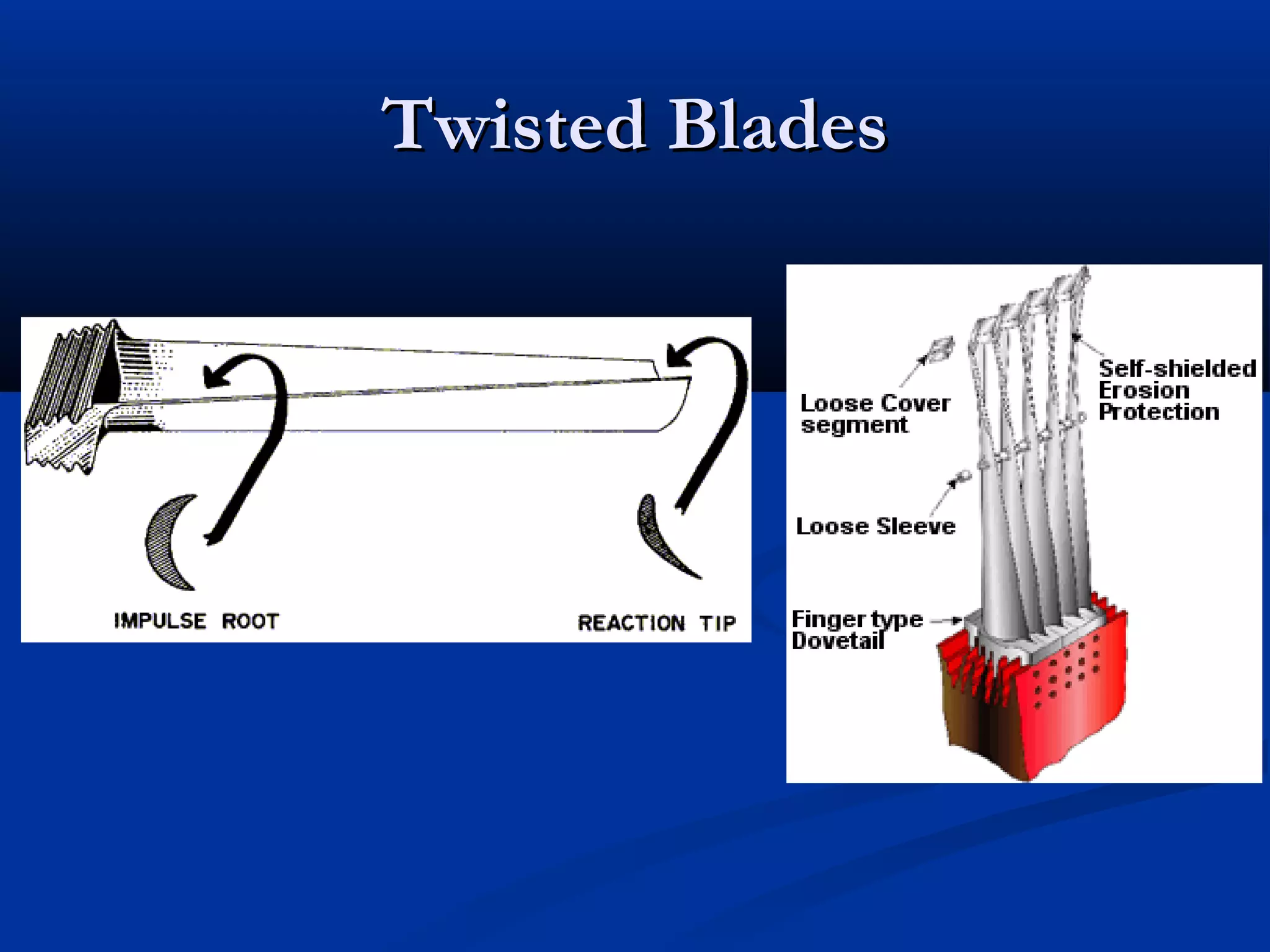


The document discusses the principles of impulse and reaction steam turbines. It explains that impulse turbines use nozzles to convert steam pressure entirely into velocity before striking moving blades, while reaction turbines use both fixed and moving blades to gradually convert pressure to velocity. Compounding is also discussed as a way to achieve higher expansion ratios by dividing the expansion across multiple stages.


![[PPT] on Steam Turbine](https://cdn.slidesharecdn.com/ss_thumbnails/spsharmafinalppt-140608082156-phpapp01-thumbnail.jpg?width=640&height=640&fit=bounds)


