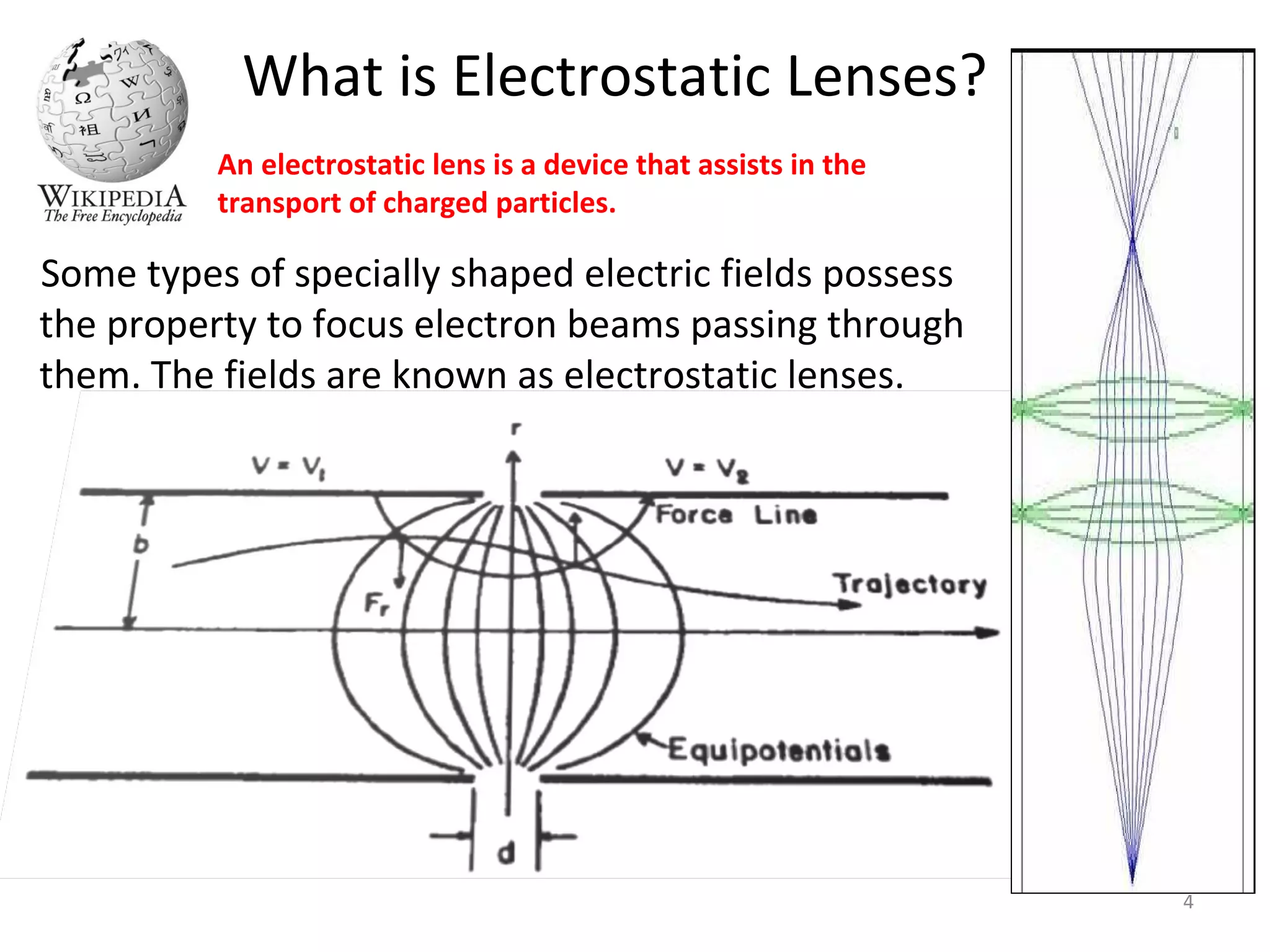
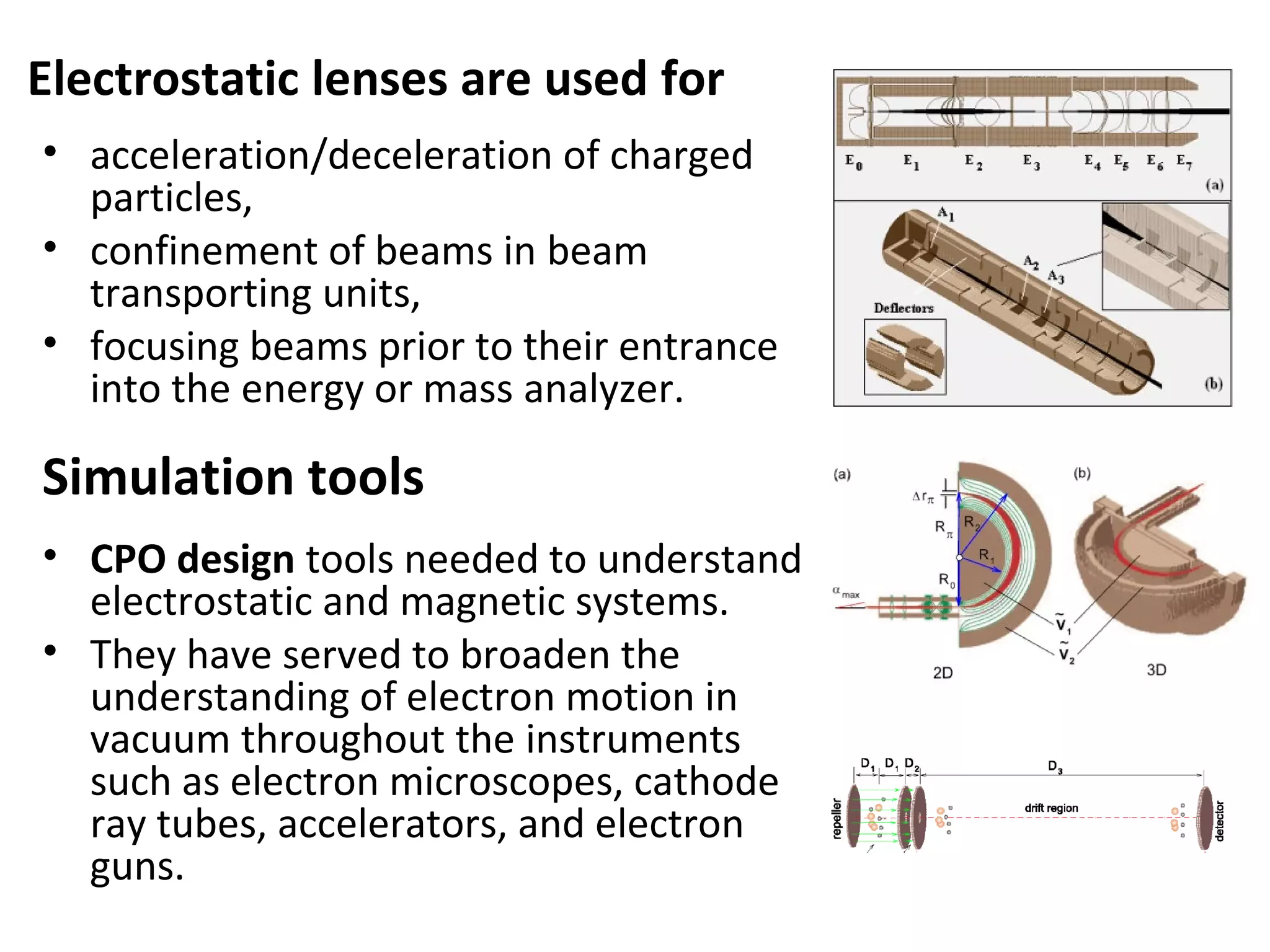
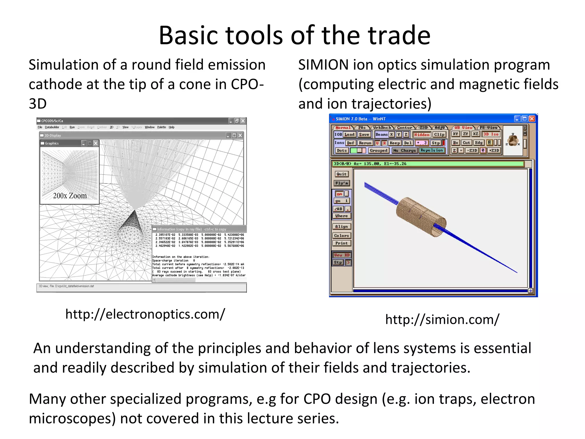
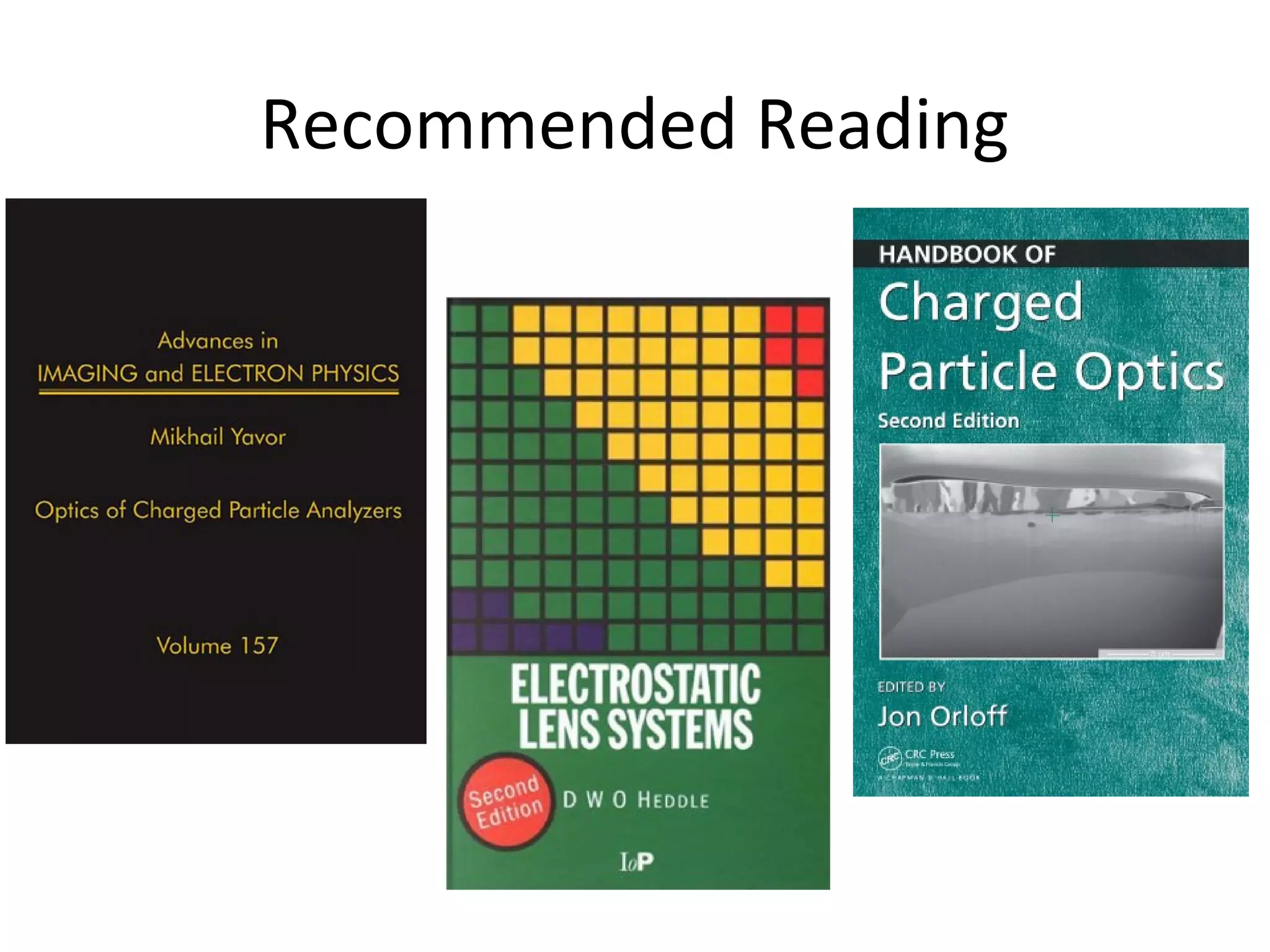
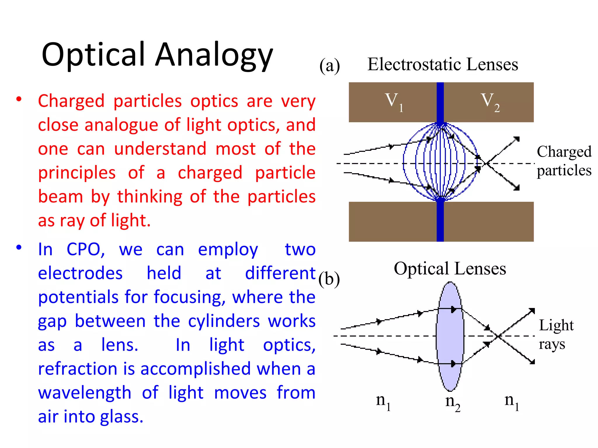
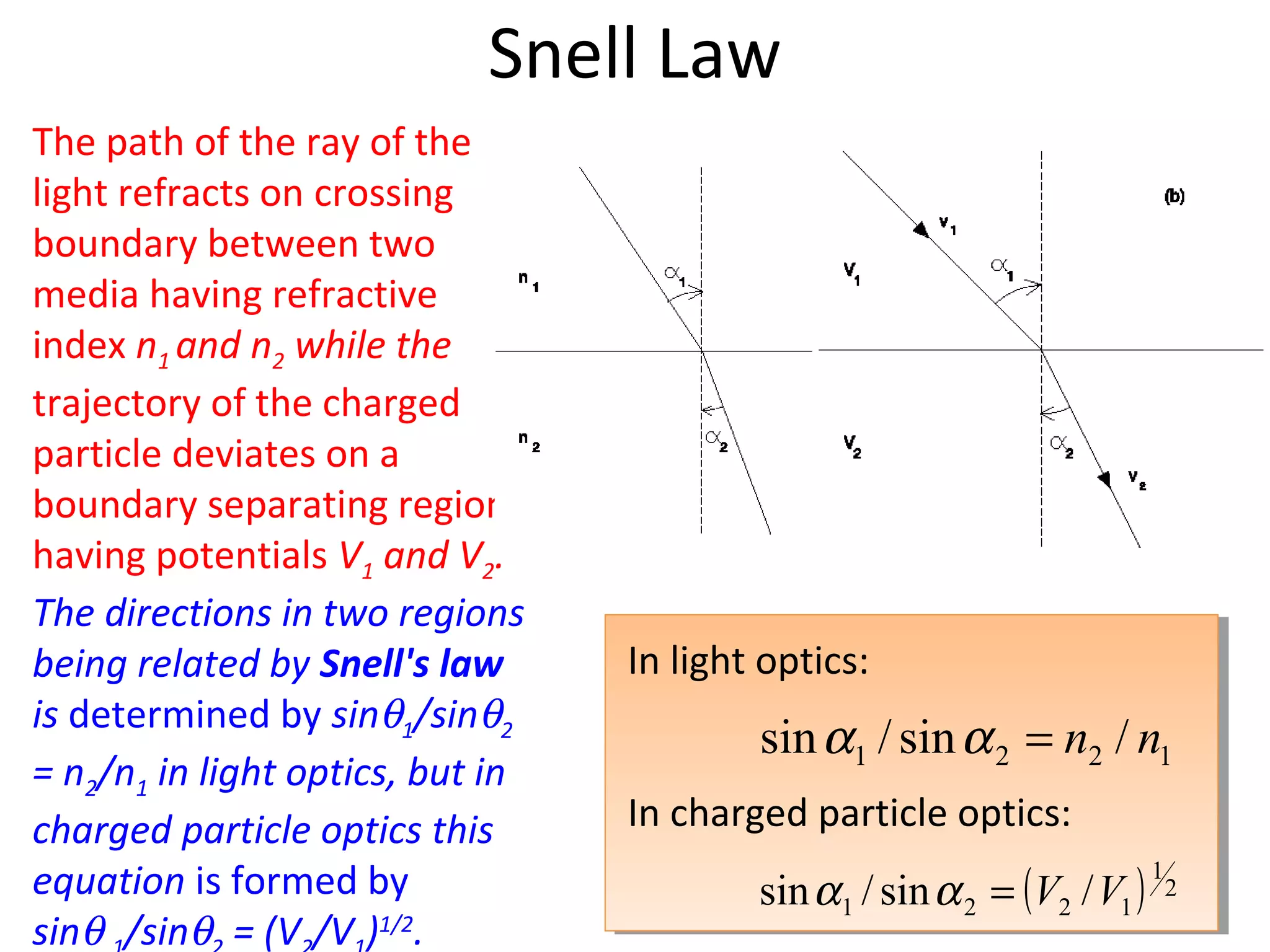
Dr. Omer Sise
Afyon Kocatepe University, TURKEY
omersise@aku.edu.tr
Lecture 1.
Introductory Guide to Electrostatic Lenses
Charged Particle Optics:
Theory & Simulation
My Current Adress:
Suleyman Demirel University, TURKEY
omersise@sdu.edu.tr
omersise.com
Goals and Objectives
• knowledge
– analogies between charged particle and light optics
– control of electron and positron beams
– principles of imaging in a lens
– the optics of simple lens systems
– paraxial approximation and aberrations
– data on simple lenses consisting of multi-apertures or
cylinders.
• ability
– calculate the focal and aberration properties of a range of
lenses
– design a beam transport system
Why we need
electrostatic
lenses anyway?
Many physicists using electron or
ion spectrometers, electron/ion
gun and beam transport system
needs some knowledge of
electrostatic lenses.
This lecture is an introduction and I will do my best to let
you in on the basics first and than we will discuss some of
the applications of electrostatic lenses.
This is recommended to people who are studying or work
with vacuum electronics and charged-particle beam
technology: students, postgraduate students, engineers,
research workers.
4
What is Electrostatic Lenses?
Some types of specially shaped electric fields possess
the property to focus electron beams passing through
them. The fields are known as electrostatic lenses.
An electrostatic lens is a device that assists in the
transport of charged particles.
Electrostatic lenses are used for
• acceleration/deceleration of charged
particles,
• confinement of beams in beam
transporting units,
• focusing beams prior to their entrance
into the energy or mass analyzer.
• CPO design tools needed to understand
electrostatic and magnetic systems.
• They have served to broaden the
understanding of electron motion in
vacuum throughout the instruments
such as electron microscopes, cathode
ray tubes, accelerators, and electron
guns.
Simulation tools
Basic tools of the trade
Many other specialized programs, e.g for CPO design (e.g. ion traps, electron
microscopes) not covered in this lecture series.
SIMION ion optics simulation program
(computing electric and magnetic fields
and ion trajectories)
http://simion.com/
Simulation of a round field emission
cathode at the tip of a cone in CPO-
3D
http://electronoptics.com/
An understanding of the principles and behavior of lens systems is essential
and readily described by simulation of their fields and trajectories.
Recommended Reading
Other books
P. Grivet, Electron Optics, Pergamon Press, London, 1965.
B. Paszkowski, Electron Optics, Iliffe, London, 1968.
O. Klemperer, M.E. Barnett, Electron Optics, third ed., Cambridge
Uniniversity Press, Cambridge, 1971.
E. Harting, F.H. Read, Electrostatic Lenses, Elsevier, Amsterdam,
1976.
H. Wollnik, Optics of Charged Particles, Academic Press, Orlando,
1987
M. Szilagyi, Electron and Ion Optics, Plenum, New York, 1988.
P. W. Hawkes, E. Kasper, Principles of Electron Optics, vols. 1 and
2,
Academic Press, London, 1989.
El-Kareh A B and El-Kareh J C J, Electron Beams, Lenses and Optics
(London: Academic) 1970
• Light optics can hardly be discussed without
optical lenses. Therefore, Charged Particle Optics
requires knowledge of optical elements:
electrostatic and magnetic lenses.
• Analogy between Light Optics and Charged
Particle Optics is useful but limited.
• It is customary in charged particle optics
discussions to make use of the same terminology
and formulae. Terms have a one-to-one
correspondence between the two fields.
Introductory remarks
(a)
(b)
Electrostatic Lenses
Optical Lenses
Charged
particles
Light
rays
V1
n1
V2
n2
n1
Optical Analogy
• Charged particles optics are very
close analogue of light optics, and
one can understand most of the
principles of a charged particle
beam by thinking of the particles
as ray of light.
• In CPO, we can employ two
electrodes held at different
potentials for focusing, where the
gap between the cylinders works
as a lens. In light optics,
refraction is accomplished when a
wavelength of light moves from
air into glass.
In light optics:
In charged particle optics:
Snell Law
1221 /sin/sin nn=αα
( ) 2
1
1221 /sin/sin VV=αα
The path of the ray of the
light refracts on crossing
boundary between two
media having refractive
index n1 and n2 while the
trajectory of the charged
particle deviates on a
boundary separating regions
having potentials V1 and V2.
The directions in two regions
being related by Snell's law
is determined by sinθ1/sinθ2
= n2/n1 in light optics, but in
charged particle optics this
equation is formed by
sinθ /sinθ = (V /V )1/2
.
Significant differences
• In light optics there is one refractive surface when the ray passes to
another region; however, in particle optics, there are an infinite
number of equipotential surfaces which deviate the beam of
charged particles at different regions. Changes in the “refractive
index” are gradual so rays are continuous curves rather than broken
straight lines.
• The other difference is the effect of space charge, due to the
mutual repulsion of the charged particles, on image formation. An
excellent summary of this and other limitations of the analogy
between light and particle optics is provided in El-Kareh A B and El-
Kareh J C J 1970.
• In light optics, glass surfaces can be shaped to reduce aberrations,
while in CPO aberrations cannot be avoided in round lenses.
Because, spatial distribution of the electric potentials cannot be
formed arbitrarily due to the Laplace equation (Scherzer theorem).
Action of a Lens
Converging Lens
Diverging Lens
The
equipotential
lines in the plot
indicate the
intersection with
the plane of the
drawing of
surfaces on
which the
electrostatic
potential is a
constant.
Lens Parameters
• For any of electrostatic lens it is possible to define focal
points, principal planes, and focal lengths in the same
manner as for light lenses and to determine with their aid
linear or angular magnification for any object position. All
the ideal lens formulas apply to electrostatic lenses.
• The field of the lens is restricted along the optic axis.
• The field-free region in front of the lens is called the
object space, and behind the lens it is called the image
space.
Focal and Principal Planes
• A paraxial trajectory entering the lens from the object
space parallel to the optic axis is bent by the lens field;
• This trajectory (or its asymptote in the backward
direction) in the image space cross the optic axis at the
profile plane, called the focal plane of the lens.
• The asymptotes of the considered trajectory from the
object space and from the image space intersect at
some plane H2; this plane is called the principal plane of
the lens.
• The distance f2=F2-H2 is called the focal length of the
lens.
• Similarly, one can consider a paraxial particle trajectory
entering the lens field in the backward direction from
the image space parallel to the optic axis.
Electron Optical Properties
• Electron optical properties of a lens are determined by
positions of the principal planes and one of focal lengths.
• Because of that the set of focal and principal planes is
called cardinal elements of a lens.
• When on both sides of a lens potential is constant and has
the same value it is called a unipotential (or einzel) lens.
• If potentials are constant but have different values on the
two sides of the lens, it is known as an immersion lens.
Helmholtz-Lagrange Law
• The linear magnification, M, relates the size of the image to
the size of the object. M is given simply by the ratio of the
final to the initial beam diameter in the radial axis, r2/r1.
• Equally important in electron optics is to understand how the
angular divergence of an electron beam will change during
the image formation process. The so-called angular
magnification is then given by Mα . It is interesting, and also a
very important result, that if we multiply together the two
equations for the angular and linear magnifications, the
product is always equal to
This is the Abbe–Helmholtz sine approximation to the
Helmholtz–Lagrange law described by
• we may evaluate the magnitude of the final image
• This expression shows that the cross section of the beam
in the target plane (reducing r2), can be obtained by
reducing the cathode size (r1), the potential in the near
cathode region (V1) and the aperture angle α1 at the
cathode side. However, the reduction of the numerator of
this expression can hardly be accomplished in practice.
Prof. G. King, Lecture Notes
In CPO, apertures are used in electrostatic lenses to define the beam. A
window aperture defines the radial size of the beam and a pupil aperture
defines the angular extent of the beam. The lens produces an image of the
window. As the beam has passed from potential V1 to V2, there has also been a
change of energy. The angular extent of the beam is minimized by placing the
pupil at the focal length of the lens. This produces a zero beam angle and
hence the angular extent of the beam is solely defined by the pencil angle (θ).
http://es1.ph.man.ac.uk/george-king/gcking.html
o Question now? ASK!
o Any topic you want to hear and I haven’t talked
about? Please, let me know!

Lens lect 01

  • 1.
    Dr. Omer Sise AfyonKocatepe University, TURKEY omersise@aku.edu.tr Lecture 1. Introductory Guide to Electrostatic Lenses Charged Particle Optics: Theory & Simulation My Current Adress: Suleyman Demirel University, TURKEY omersise@sdu.edu.tr omersise.com
  • 2.
    Goals and Objectives •knowledge – analogies between charged particle and light optics – control of electron and positron beams – principles of imaging in a lens – the optics of simple lens systems – paraxial approximation and aberrations – data on simple lenses consisting of multi-apertures or cylinders. • ability – calculate the focal and aberration properties of a range of lenses – design a beam transport system
  • 3.
    Why we need electrostatic lensesanyway? Many physicists using electron or ion spectrometers, electron/ion gun and beam transport system needs some knowledge of electrostatic lenses. This lecture is an introduction and I will do my best to let you in on the basics first and than we will discuss some of the applications of electrostatic lenses. This is recommended to people who are studying or work with vacuum electronics and charged-particle beam technology: students, postgraduate students, engineers, research workers.
  • 4.
    4 What is ElectrostaticLenses? Some types of specially shaped electric fields possess the property to focus electron beams passing through them. The fields are known as electrostatic lenses. An electrostatic lens is a device that assists in the transport of charged particles.
  • 5.
    Electrostatic lenses areused for • acceleration/deceleration of charged particles, • confinement of beams in beam transporting units, • focusing beams prior to their entrance into the energy or mass analyzer. • CPO design tools needed to understand electrostatic and magnetic systems. • They have served to broaden the understanding of electron motion in vacuum throughout the instruments such as electron microscopes, cathode ray tubes, accelerators, and electron guns. Simulation tools
  • 6.
    Basic tools ofthe trade Many other specialized programs, e.g for CPO design (e.g. ion traps, electron microscopes) not covered in this lecture series. SIMION ion optics simulation program (computing electric and magnetic fields and ion trajectories) http://simion.com/ Simulation of a round field emission cathode at the tip of a cone in CPO- 3D http://electronoptics.com/ An understanding of the principles and behavior of lens systems is essential and readily described by simulation of their fields and trajectories.
  • 7.
  • 8.
    Other books P. Grivet,Electron Optics, Pergamon Press, London, 1965. B. Paszkowski, Electron Optics, Iliffe, London, 1968. O. Klemperer, M.E. Barnett, Electron Optics, third ed., Cambridge Uniniversity Press, Cambridge, 1971. E. Harting, F.H. Read, Electrostatic Lenses, Elsevier, Amsterdam, 1976. H. Wollnik, Optics of Charged Particles, Academic Press, Orlando, 1987 M. Szilagyi, Electron and Ion Optics, Plenum, New York, 1988. P. W. Hawkes, E. Kasper, Principles of Electron Optics, vols. 1 and 2, Academic Press, London, 1989. El-Kareh A B and El-Kareh J C J, Electron Beams, Lenses and Optics (London: Academic) 1970
  • 9.
    • Light opticscan hardly be discussed without optical lenses. Therefore, Charged Particle Optics requires knowledge of optical elements: electrostatic and magnetic lenses. • Analogy between Light Optics and Charged Particle Optics is useful but limited. • It is customary in charged particle optics discussions to make use of the same terminology and formulae. Terms have a one-to-one correspondence between the two fields. Introductory remarks
  • 10.
    (a) (b) Electrostatic Lenses Optical Lenses Charged particles Light rays V1 n1 V2 n2 n1 OpticalAnalogy • Charged particles optics are very close analogue of light optics, and one can understand most of the principles of a charged particle beam by thinking of the particles as ray of light. • In CPO, we can employ two electrodes held at different potentials for focusing, where the gap between the cylinders works as a lens. In light optics, refraction is accomplished when a wavelength of light moves from air into glass.
  • 11.
    In light optics: Incharged particle optics: Snell Law 1221 /sin/sin nn=αα ( ) 2 1 1221 /sin/sin VV=αα The path of the ray of the light refracts on crossing boundary between two media having refractive index n1 and n2 while the trajectory of the charged particle deviates on a boundary separating regions having potentials V1 and V2. The directions in two regions being related by Snell's law is determined by sinθ1/sinθ2 = n2/n1 in light optics, but in charged particle optics this equation is formed by sinθ /sinθ = (V /V )1/2 .
  • 12.
    Significant differences • Inlight optics there is one refractive surface when the ray passes to another region; however, in particle optics, there are an infinite number of equipotential surfaces which deviate the beam of charged particles at different regions. Changes in the “refractive index” are gradual so rays are continuous curves rather than broken straight lines. • The other difference is the effect of space charge, due to the mutual repulsion of the charged particles, on image formation. An excellent summary of this and other limitations of the analogy between light and particle optics is provided in El-Kareh A B and El- Kareh J C J 1970. • In light optics, glass surfaces can be shaped to reduce aberrations, while in CPO aberrations cannot be avoided in round lenses. Because, spatial distribution of the electric potentials cannot be formed arbitrarily due to the Laplace equation (Scherzer theorem).
  • 13.
    Action of aLens Converging Lens Diverging Lens The equipotential lines in the plot indicate the intersection with the plane of the drawing of surfaces on which the electrostatic potential is a constant.
  • 14.
    Lens Parameters • Forany of electrostatic lens it is possible to define focal points, principal planes, and focal lengths in the same manner as for light lenses and to determine with their aid linear or angular magnification for any object position. All the ideal lens formulas apply to electrostatic lenses. • The field of the lens is restricted along the optic axis. • The field-free region in front of the lens is called the object space, and behind the lens it is called the image space.
  • 15.
  • 16.
    • A paraxialtrajectory entering the lens from the object space parallel to the optic axis is bent by the lens field; • This trajectory (or its asymptote in the backward direction) in the image space cross the optic axis at the profile plane, called the focal plane of the lens. • The asymptotes of the considered trajectory from the object space and from the image space intersect at some plane H2; this plane is called the principal plane of the lens. • The distance f2=F2-H2 is called the focal length of the lens. • Similarly, one can consider a paraxial particle trajectory entering the lens field in the backward direction from the image space parallel to the optic axis.
  • 17.
    Electron Optical Properties •Electron optical properties of a lens are determined by positions of the principal planes and one of focal lengths. • Because of that the set of focal and principal planes is called cardinal elements of a lens. • When on both sides of a lens potential is constant and has the same value it is called a unipotential (or einzel) lens. • If potentials are constant but have different values on the two sides of the lens, it is known as an immersion lens.
  • 18.
    Helmholtz-Lagrange Law • Thelinear magnification, M, relates the size of the image to the size of the object. M is given simply by the ratio of the final to the initial beam diameter in the radial axis, r2/r1. • Equally important in electron optics is to understand how the angular divergence of an electron beam will change during the image formation process. The so-called angular magnification is then given by Mα . It is interesting, and also a very important result, that if we multiply together the two equations for the angular and linear magnifications, the product is always equal to This is the Abbe–Helmholtz sine approximation to the Helmholtz–Lagrange law described by
  • 19.
    • we mayevaluate the magnitude of the final image • This expression shows that the cross section of the beam in the target plane (reducing r2), can be obtained by reducing the cathode size (r1), the potential in the near cathode region (V1) and the aperture angle α1 at the cathode side. However, the reduction of the numerator of this expression can hardly be accomplished in practice.
  • 20.
    Prof. G. King,Lecture Notes In CPO, apertures are used in electrostatic lenses to define the beam. A window aperture defines the radial size of the beam and a pupil aperture defines the angular extent of the beam. The lens produces an image of the window. As the beam has passed from potential V1 to V2, there has also been a change of energy. The angular extent of the beam is minimized by placing the pupil at the focal length of the lens. This produces a zero beam angle and hence the angular extent of the beam is solely defined by the pencil angle (θ). http://es1.ph.man.ac.uk/george-king/gcking.html
  • 21.
    o Question now?ASK! o Any topic you want to hear and I haven’t talked about? Please, let me know!

Editor's Notes

  • #2 I will discuss t he influence of the geometric parameters on the focal points, magnification, and aberration c oefficient s.
  • #20 the cathode emissivity cannot be as much as desired and, in order to obtain the beam current necessary for normal operation, one has to use a cathode with a comparatively large emissive surface. Reduction of the potential in the near cathode region is inexpedient for two reasons: (1) the lower the potential, the greater the influence of the initial velocities of the electrons, the higher the chromatic aberration of the lens; (2) the slower the electrons, the greater the effect of space charge leading to expansions of the beam due to the Coulomb repulsive forces.