Downloaded 418 times


![2. Getting started
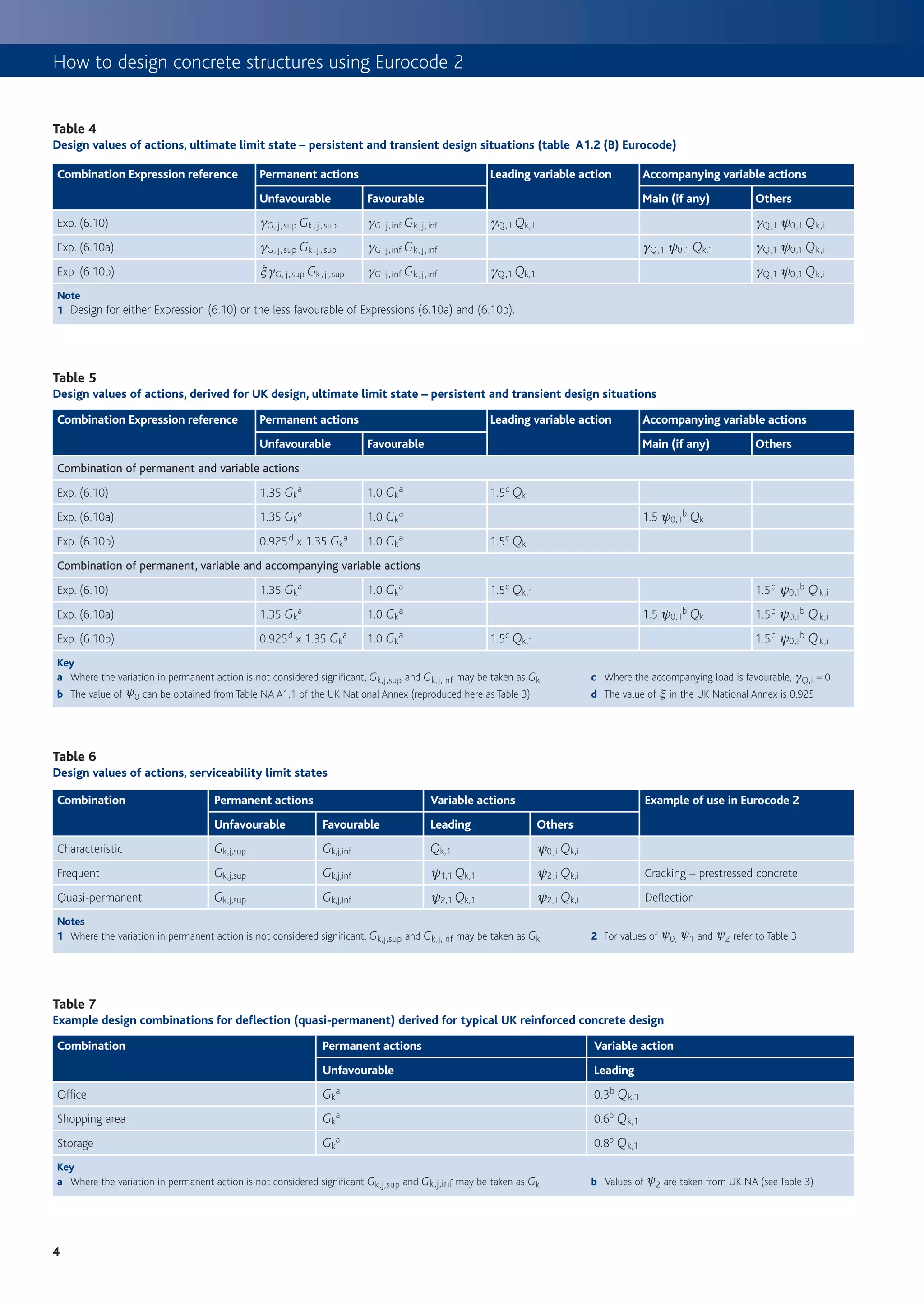
Stability and imperfections Crack control
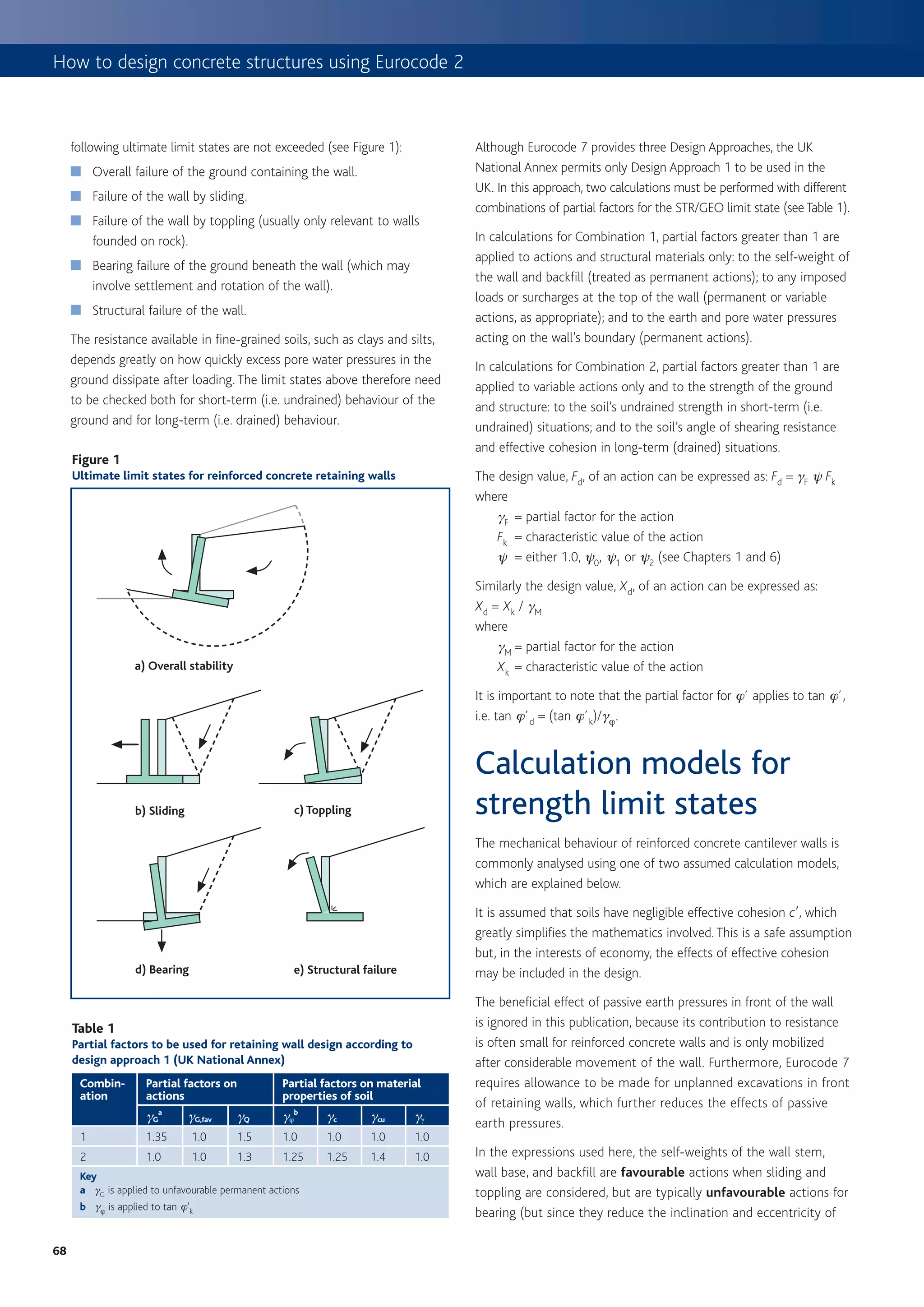
The effects of geometric imperfections should be considered in Crack widths should be limited to ensure appearance and durability
combination with the effects of wind loads (i.e. not as an alternative are satisfactory. In the absence of specific durability requirements
load combination). For global analysis, the imperfections may be (e.g. water tightness) the crack widths may be limited to 0.3 mm in
represented by an inclination y i . all exposure classes under the quasi-permanent combination. In the
absence of requirements for appearance, this limit may be relaxed (to
y i = (1/200) x a h x a m say 0.4 mm) for exposure classes X0 and XC1 (refer to Table 7). The
where theoretical size of the crack can be calculated using the expressions
a h = (2/Rl), to be taken as not less than 2/3 nor greater than 1.0 given in Cl 7.3.4 from Eurocode 2–1–1 or from the ‘deemed to satisfy’
a m = [0.5 (1 + 1/m)]0.5 requirements that can be obtained from Table 11, which is based on
l is the height of the building in metres tables 7.2N and 7.3N of the Eurocode. The limits apply to either the
m is the number of vertical members contributing to the horizontal bar size or the bar spacing, not both.
force in the bracing system.
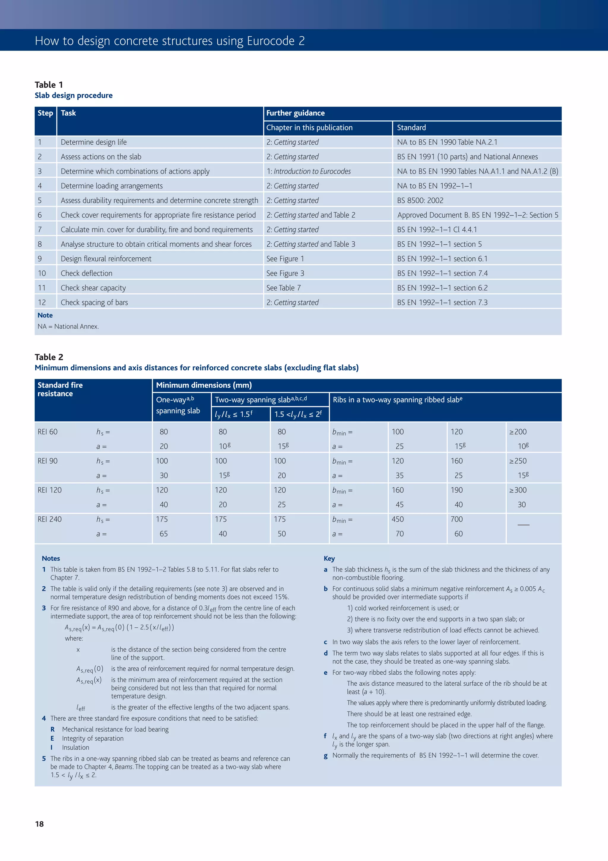
Figure 5
The effect of the inclination may be represented by transverse forces at Examples of the effect of geometric imperfections
each level and included in the analysis along with other actions (see
Figure 5):
Effect on bracing system: Hi = y i (Nb – Na)
Effect on floor diaphragm: Hi = y i (Nb + Na)/2
Effect on roof diaphragm: Hi = y i Na
where Na and Nb are longitudinal forces contributing to Hi.
In most cases, an allowance for imperfections is made in the partial
factors used in the design of elements. However for columns, the effect a) Bracing system b) Floor diaphragm c) Roof diaphragm
of imperfections, which is similar in principle to the above, must be
considered (see Chapter 5, originally published as Columns15).
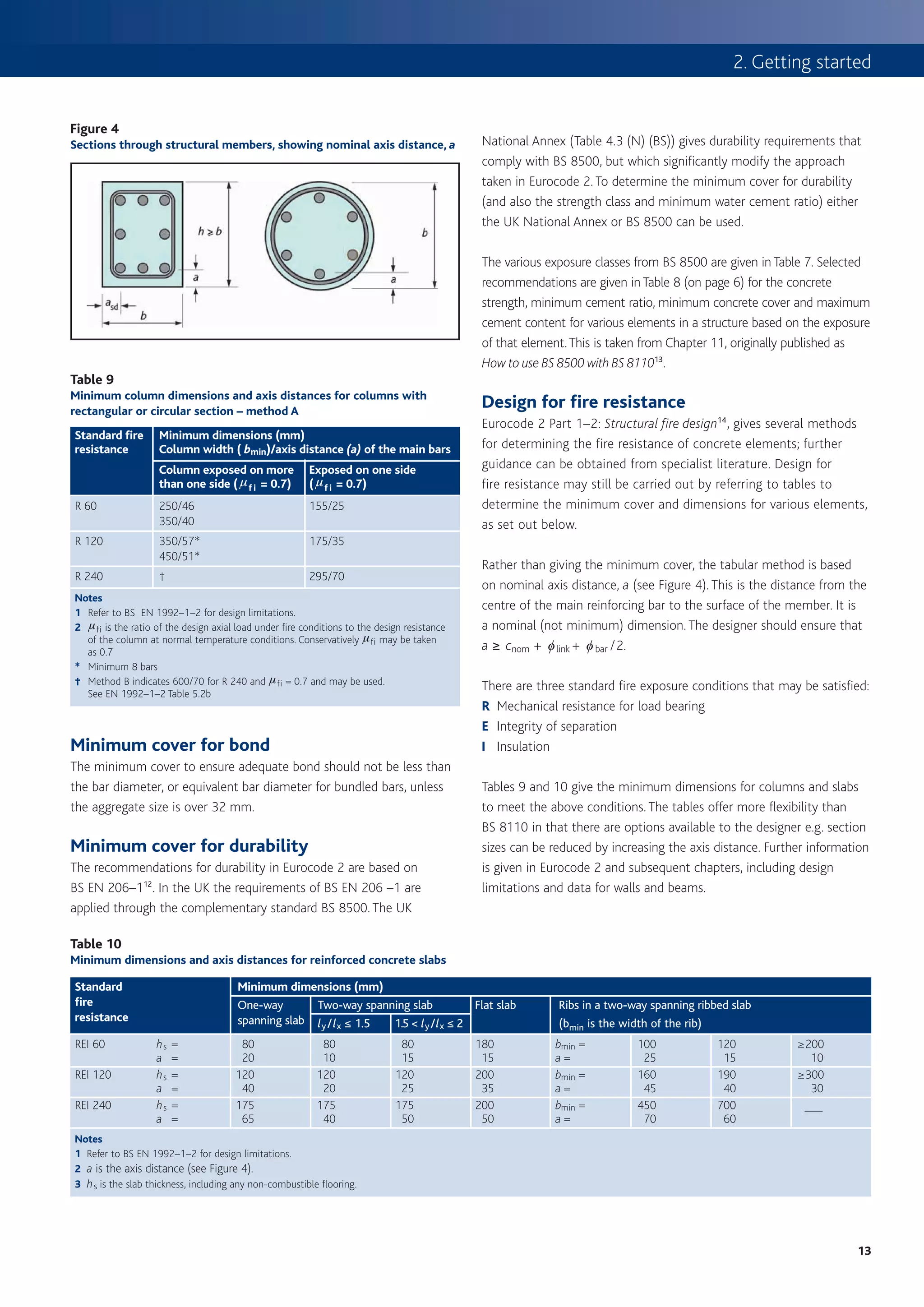
Figure 6
Determination of steel stress for crack width control
Table 11
Maximum bar size or spacing to limit crack width
Steel wmax = 0.4 mm wmax = 0.3 mm
stress
Maximum Maximum Maximum Maximum
(s s)MPa bar bar bar bar
size (mm) spacing (mm) size (mm) spacing (mm)
160 40 300 32 300
200 32 OR 300 25 OR 250
240 20 250 16 200
280 16 200 12 150
320 12 150 10 100
360 10 100 8 50
Note
The steel stress may be estimated from the expression below (or see Figure 6):
ss = fyk m As,req
gms n As,prov d
where
fyk = characteristic reinforcement yield stress
gms = partial factor for reinforcing steel
m = total load from quasi-permanent combination
n = total load from ULS combination To determine stress in the reinforcement (ss), calculate the ratio Gk/Qk,
As,req = area of reinforcement at the ULS read up the graph to the appropriate curve and read across to determine ssu .
As,req 1
As,prov = area of reinforcement provided
d = ratio of redistributed moment to elastic moment
ss can be calculated from the expression: ss = ssu (As,prov d)( )
7
15](https://image.slidesharecdn.com/howtodesignconcretestructuresusingeurocode2-100408075224-phpapp02/75/How-To-Design-Concrete-Structures-Using-Eurocode-2-19-2048.jpg)
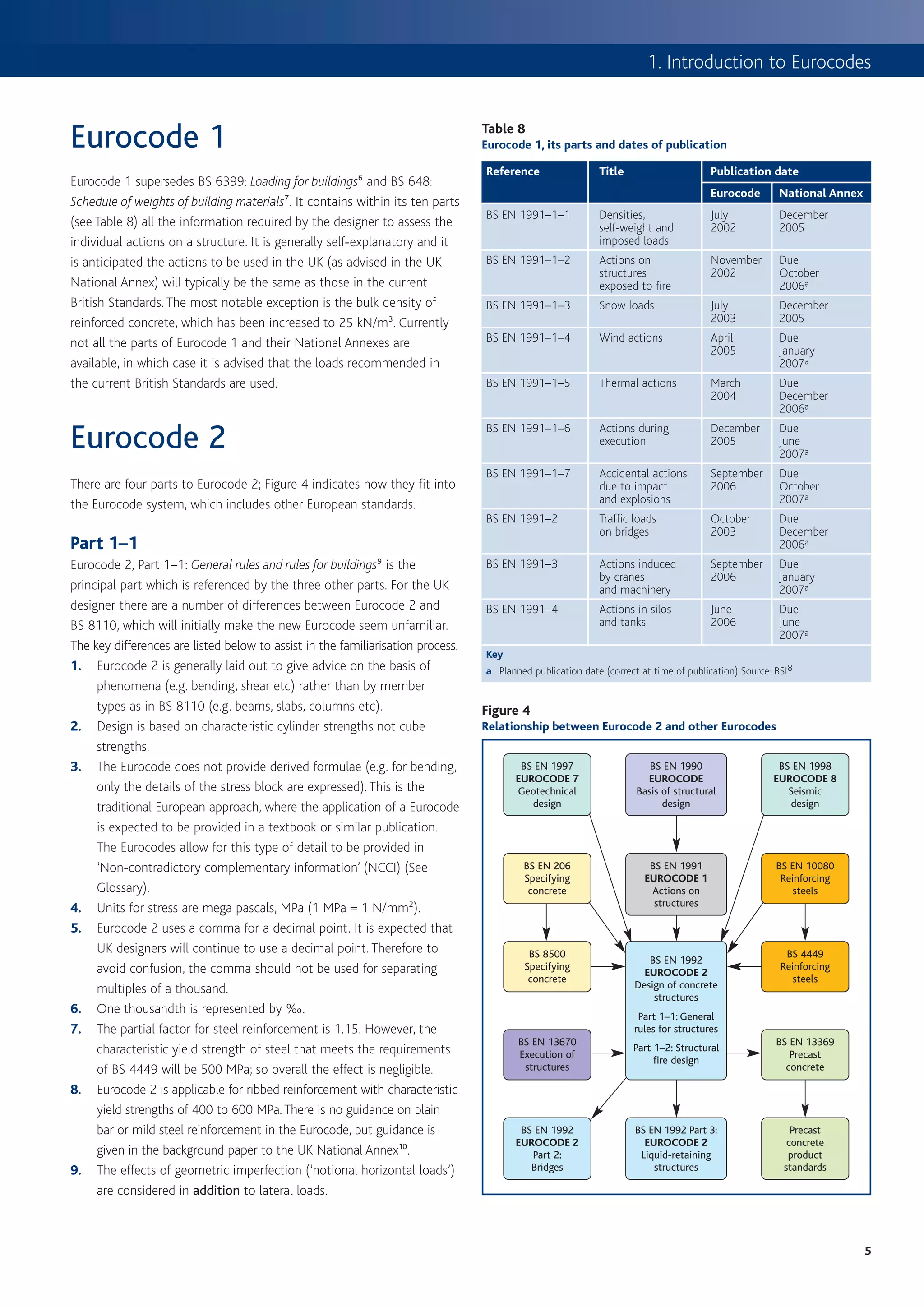
![3. Slabs
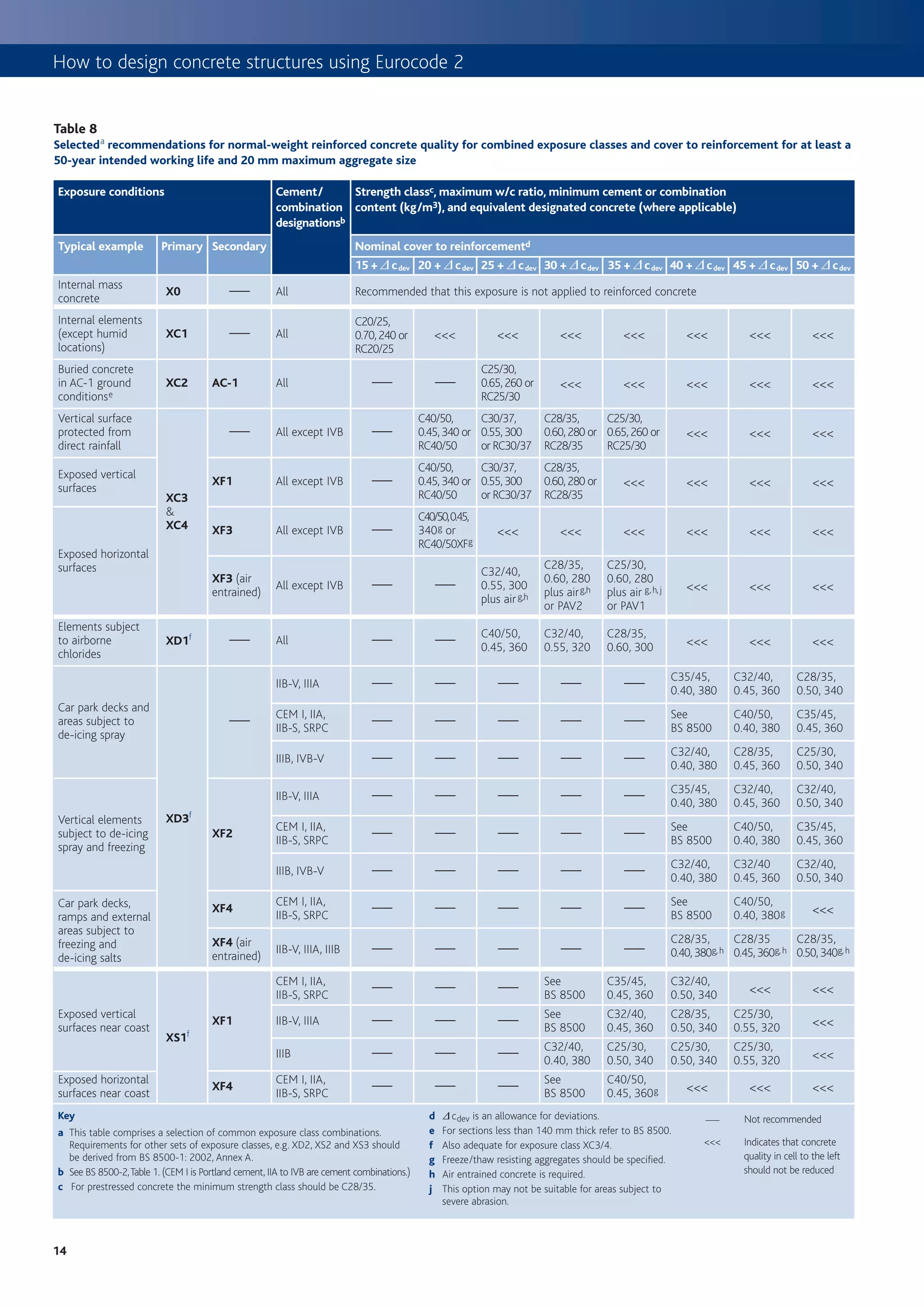
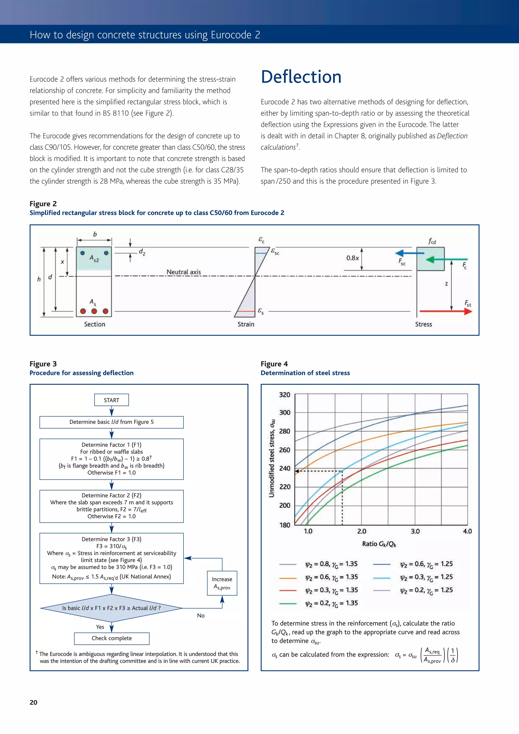
Figure 1
Procedure for determining flexural reinforcement dimension, so the designer should ensure that
a ≥ cnom + f link + f bar /2.
START The requirements for various types of slab are given in Table 2.
Carry out analysis of slab to determine design moments (M)
(Where appropriate use coefficients from Table 3) Flexure
The design procedure for flexural design is given in Figure 1; this
No Outside scope of includes derived formulae based on the simplified rectangular stress
Concrete class
≤C50/60? this publication block from Eurocode 2. Where appropriate, Table 3 may be used to
determine bending moments and shear forces for slabs. Further
Yes information for the design of two-way, ribbed or waffle slabs is given in
Determine K from: K =
M the appropriate sections on pages 5 and 6.
bd 2 fck
Table 4
Determine K’ from Table 4 or
Values for K ’
K’ = 0.60d – 0.18 d 2 – 0.21 where d ≤ 1.0
% redistribution d (redistribution ratio) K’
0 1.00 0.208a
Compression
reinforcement
10 0.90 0.182a
No
Is K ≤ K ’ ? required – not 15 0.85 0.168
recommended for
typical slabs 20 0.80 0.153
Yes
25 0.75 0.137
30 0.70 0.120
No compression reinforcement required Key
a It is often recomended in the UK that K´ should be limited to 0.168 to ensure ductile failure.
Obtain lever arm z from Table 5 or
d Table 5
z=
2 [
1 + 1 – 3.53 K ≤ 0.95d] z/d for singly reinforced rectangular sections
K z/d K z/d
Calculate tension reinforcement required from ≤0.05 0.950a 0.13 0.868
M
As = 0.06 0.944 0.14 0.856
fyd z
0.07 0.934 0.15 0.843
0.08 0.924 0.16 0.830
Check minimum reinforcement requirements (see Table 6) 0.09 0.913 0.17 0.816
0.26 fctm bt d 0.10 0.902 0.18 0.802
As,min = where fck ≥ 25
fyk 0.11 0.891 0.19 0.787
0.12 0.880 0.20 0.771
Key
Check maximum reinforcement requirements
a Limiting z to 0.95d is not a requirement of Eurocode 2, but is considered to be good practice.
As,max = 0.04 Ac for tension or compression
reinforcement outside lap locations
Table 6
Minimum percentage of reinforcement required
Table 3
Bending moment and shear coefficients for slabs fck fctm Minimum % (0.26 fctm /fyka )
25 2.6 0.13%
End support /slab connection First Interior Interior
interior spans supports 28 2.8 0.14%
Pinned Continuous
support 30 2.9 0.15%
End End End End
support span support span 32 3.0 0.16%
Moment 0 0.086Fl – 0.04Fl 0.075Fl –0.086Fl 0.063Fl –0.063Fl 35 3.2 0.17%
Shear 0.40F 0.46F 0.6F 0.5F 40 3.5 0.18%
Notes 45 3.8 0.20%
1 Applicable to one-way spanning slabs where the area of each bay exceeds 30 m2,
Qk ≤ 1.25 Gk and qk ≤ 5 kN/m2 50 4.1 0.21%
2 F is the total design ultimate load, l is the span Key
3 Minimum span > 0.85 longest span, minimum 3 spans
4 Based on 20% redistribution at supports and no decrease in span moments a Where fyk = 500 MPa.
3
19](https://image.slidesharecdn.com/howtodesignconcretestructuresusingeurocode2-100408075224-phpapp02/75/How-To-Design-Concrete-Structures-Using-Eurocode-2-23-2048.jpg)
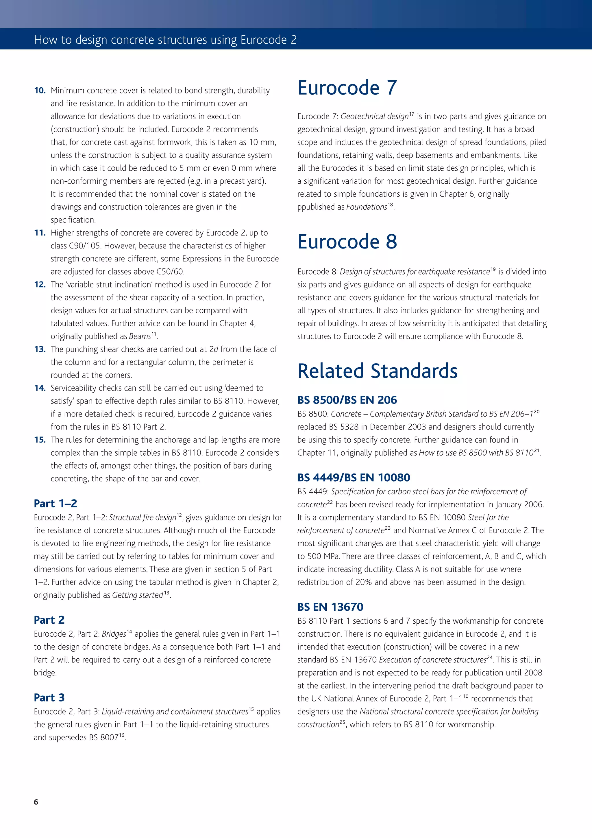
![3. Slabs
Design for shear Table 7
vRd,c resistance of members without shear reinforcement, MPa
It is not usual for a slab to contain shear reinforcement, therefore it is rI = Effective depth, d (mm)
As /(bd)
only necessary to ensure that the concrete shear stress capacity ≤200 225 250 275 300 350 400 450 500 600 750
without shear reinforcement (vRd,c – see Table 7) is more than applied
0.25% 0.54 0.52 0.50 0.48 0.47 0.45 0.43 0.41 0.40 0.38 0.36
shear stress (vEd = VEd /( bd )). Where shear reinforcement is required,
e.g. for ribs in a ribbed slab, refer to Chapter 4, originally published as 0.50% 0.59 0.57 0.56 0.55 0.54 0.52 0.51 0.49 0.48 0.47 0.45
Beams 8. 0.75% 0.68 0.66 0.64 0.63 0.62 0.59 0.58 0.56 0.55 0.53 0.51
1.00% 0.75 0.72 0.71 0.69 0.68 0.65 0.64 0.62 0.61 0.59 0.57
Two-way slabs 1.25% 0.80 0.78 0.76 0.74 0.73 0.71 0.69 0.67 0.66 0.63 0.61
1.50% 0.85 0.83 0.81 0.79 0.78 0.75 0.73 0.71 0.70 0.67 0.65
Unlike BS 8110 there is no specific guidance given in Eurocode 2 on
how to determine the bending moments for a two-way slab. The 1.75% 0.90 0.87 0.85 0.83 0.82 0.79 0.77 0.75 0.73 0.71 0.68
assessment of the bending moment can be carried out using any ≥2.00% 0.94 0.91 0.89 0.87 0.85 0.82 0.80 0.78 0.77 0.74 0.71
suitable method from Section 5 of the Code. However, co-efficients
k 2.000 1.943 1.894 1.853 1.816 1.756 1.707 1.667 1.632 1.577 1.516
may be obtained from Table 8 (taken from the Manual for the design of
building structures to Eurocode 29) to determine bending moments per Table derived from: v Rd,c = 0.12 k (100r I fck)1/3 ≥ 0.035 k1.5 fck 0.5
unit width (Msx and Msy) where: where k = 1 + R(200/d) ≤ 2 and r I = As /(bd) ≤ 0.02
Note
Msx = bsx w lx2 1 This table has been prepared for fck = 30.
2 Where r I exceeds 0.40% the following factors may be used:
Msy = b sy w lx2
fck 25 28 32 35 40 45 50
Where bsx and bsy are coefficients, lx is the shorter span and w (load
Factor 0.94 0.98 1.02 1.05 1.10 1.14 1.19
per unit area) is the STR ultimate limit state combination. For more
information on combinations refer toChapter 1, originally published as
Introduction to Eurocodes3.
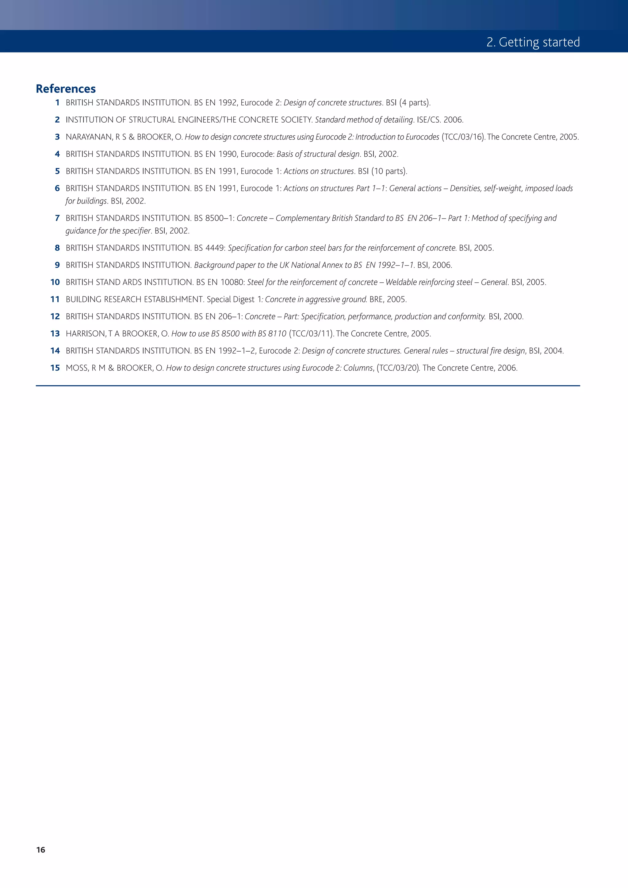
Figure 5
Basic span-to-effective-depth ratios
Notes
1 For two-way spanning slabs, the check should be
carried out on the basis of the shorter span.
2 This graph assumes simply supported span
condition (K = 1.0).
K = 1.5 for interior span condition
K = 1.3 for end span condition
K = 0.4 for cantilevers
3 Compression reinforcement, r’, has been taken as 0.
4 Curves based on the following expressions:
1.5
1.5 fck r 0 r0
l
d [
= K 11 +
r
+ 3.2 fck
( )]
r
–1
where r ≤ r 0
and
1.5 fck r 0 r’
l
d
= K 11 +[ ( r – r ’)
+
fck
12 r0 ]
where r > r 0 .
Percentage of tension reinforcement (As,req’d/bd)
5
21](https://image.slidesharecdn.com/howtodesignconcretestructuresusingeurocode2-100408075224-phpapp02/75/How-To-Design-Concrete-Structures-Using-Eurocode-2-25-2048.jpg)
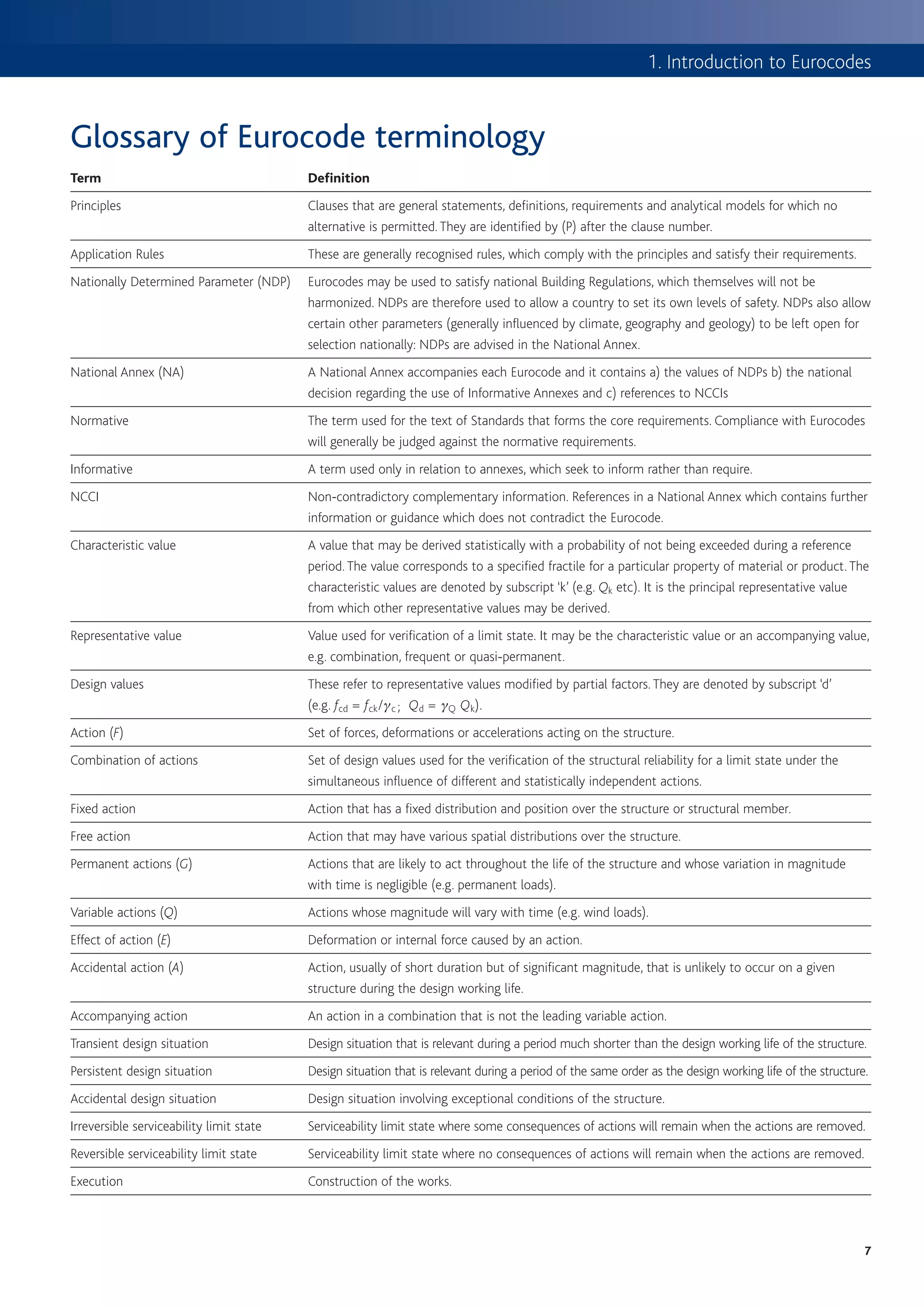
![How to design concrete structures using Eurocode 2
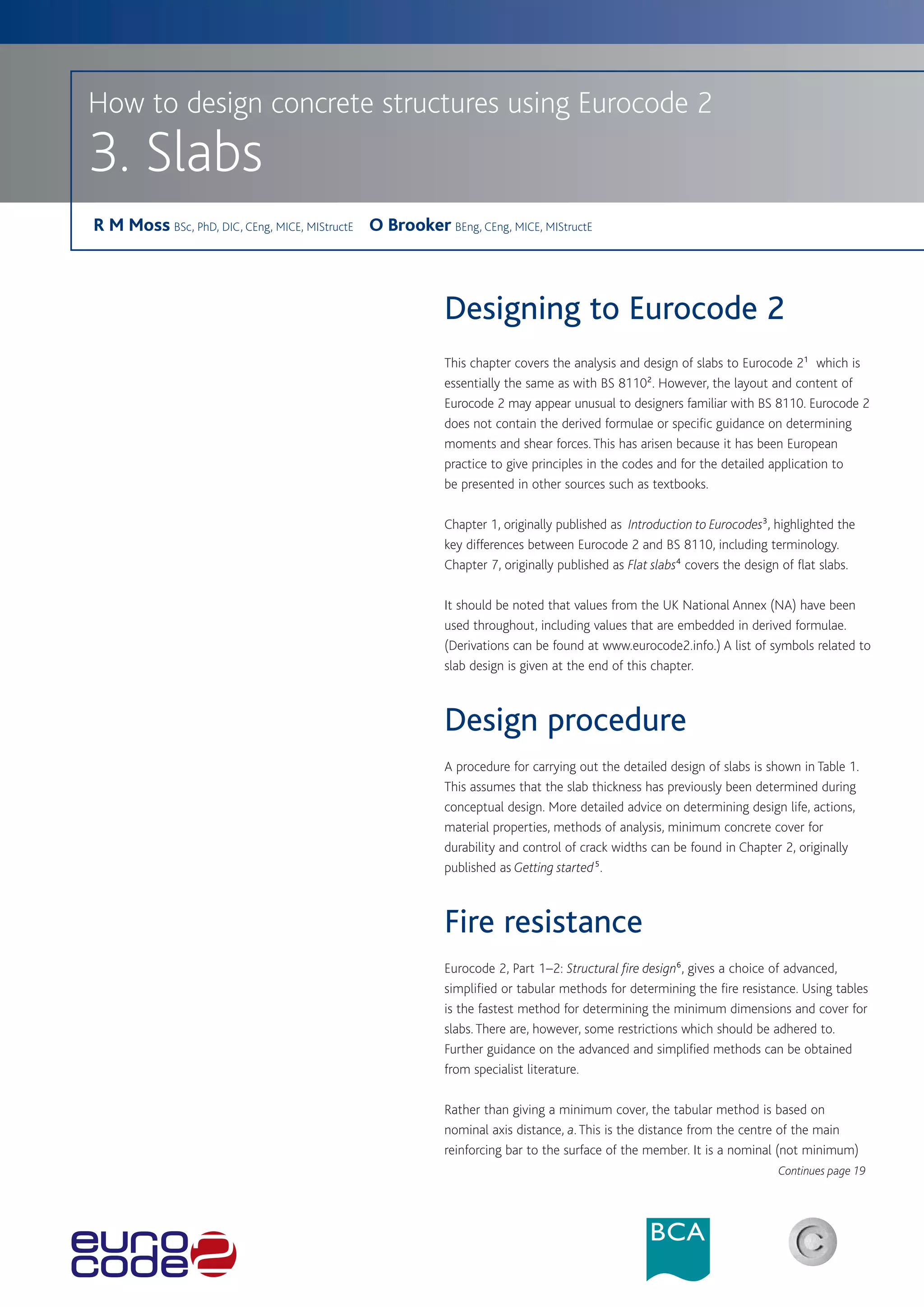
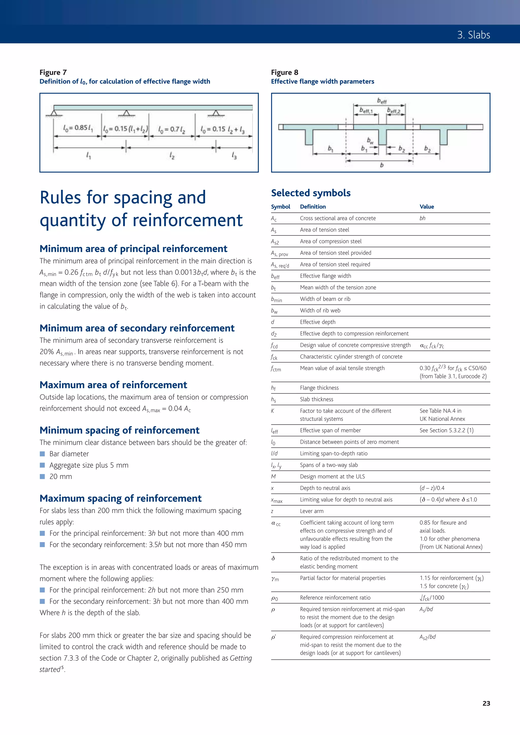
Ribbed or waffle slabs Figure 6
Procedure for determining flexural capacity of flanged ribs
Current practices for determining forces in ribbed and waffle slabs may also
START
be used for designs to Eurocode 2. Where a waffle slab is treated as a
two-way slab refer to previous section, but note that their torsional stiffness
is significantly less than for a two-way slab and the bending moment co-
efficients may not be applicable. Where it is treated as a flat slab reference No Outside scope
Concrete class of this
may be made to Chapter 7, originally published as Flat slabs4 ≤ C50/60? publication
The position of the neutral axis in the rib should be determined, and Yes
then the area of reinforcement can be calculated depending on Determine l0 (see Figure 7) and beff from:
whether it lies in the flange or web (see flow chart in Figure 6). The beff = (bw + beff1 + beff2) where
beff1 = (0.2b1 + 0.1 l0) ≤ 0.2 l0 ≤ b1
main differences compared with BS 8110 are that the assessment of
beff2 = (0.2b2 + 0.1 l0) ≤ 0.2 l0 ≤ b2
the flange width is more sophisticated (see Figures 7 and 8). Note: The flange width at the support will be
different from that at mid-span.
For symbols refer to Figures 7 and 8
Where a slab is formed with permanent blocks or a with a topping
thickness less than 50 mm and one-tenth of the clear distance
between ribs it is recommended that a longitudinal shear check is
M
carried out to determine whether additional transverse reinforcement is Determine K from: K =
bd 2 fck
required (see BS EN 1992–1–1, Cl 6.2.4).
Table 8 Determine K’ from Table 2 or
Bending moment coefficients for two-way spanning rectangular slabs
K’ = 0.60d – 0.18 d2 – 0.21 where d ≤ 1.0
supported by beams
Type or panel Short span coefficients for Long-span
and moments values of ly /lx coefficients
Calculate lever arm z from
considered for all values d
of ly /lx z=
2 [
1 + 1 – 3.53 K ≤ 0.95d ]
1.0 1.25 1.5 1.75 2.0
Interior panels Calculate depth to neutral axis x from:
x = 2.5 (d – z)
Negative moment 0.031 0.044 0.053 0.059 0.063 0.032
at continuous edge
Neutral axis in
Positive moment 0.024 0.034 0.040 0.044 0.048 0.024 Yes flange.
at midspan Is x ≤ 1.25hf Design as
rectangular
section.
One short edge discontinuous
No
Negative moment 0.039 0.050 0.058 0.063 0.067 0.037
at continuous edge Neutral axis in web
Calculate moment capacity of flange from:
Positive moment 0.029 0.038 0.043 0.047 0.050 0.028 MR,f = 0.57 fck (beff – bw) hf (d – 0.5hf)
at midspan
M – MR,f
and Kf =
One long edge discontinuous fck bw d 2
Negative moment 0.039 0.059 0.073 0.083 0.089 0.037
at continuous edge
No
Is Kf ≤ K ’ Redesign
Positive moment 0.030 0.045 0.055 0.062 0.067 0.028 section
at midspan
Two adjacent edges discontinuous Yes
Negative moment 0.047 0.066 0.078 0.087 0.093 0.045 Calculate area of reinforcement required from
at continuous edge MR,f M – MR,f
As = +
fywd (d – 0.5 hf ) fywd z
Positive moment 0.036 0.049 0.059 0.065 0.070 0.034
at midspan
6
22](https://image.slidesharecdn.com/howtodesignconcretestructuresusingeurocode2-100408075224-phpapp02/75/How-To-Design-Concrete-Structures-Using-Eurocode-2-26-2048.jpg)

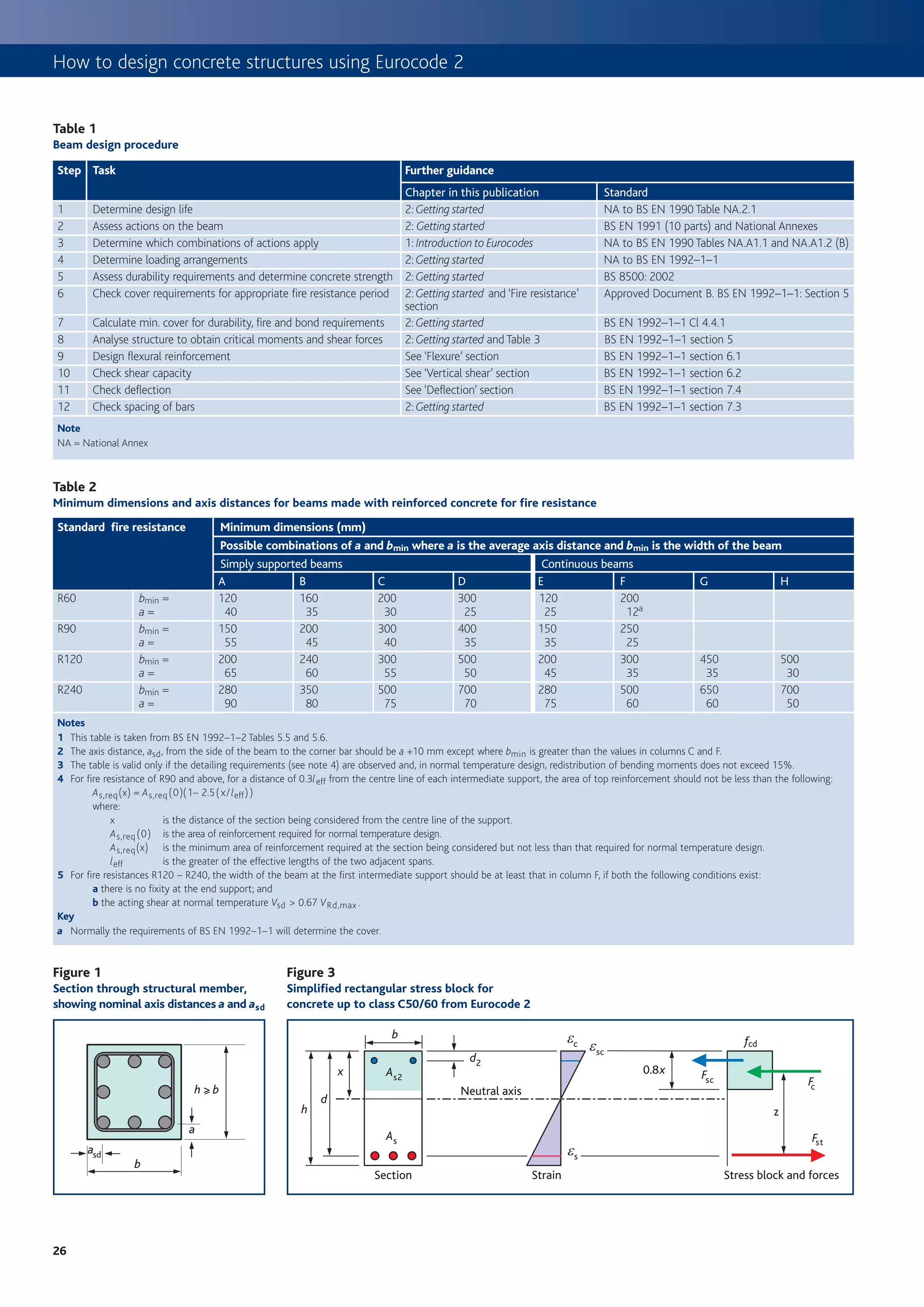
![4. Beams
Figure 2
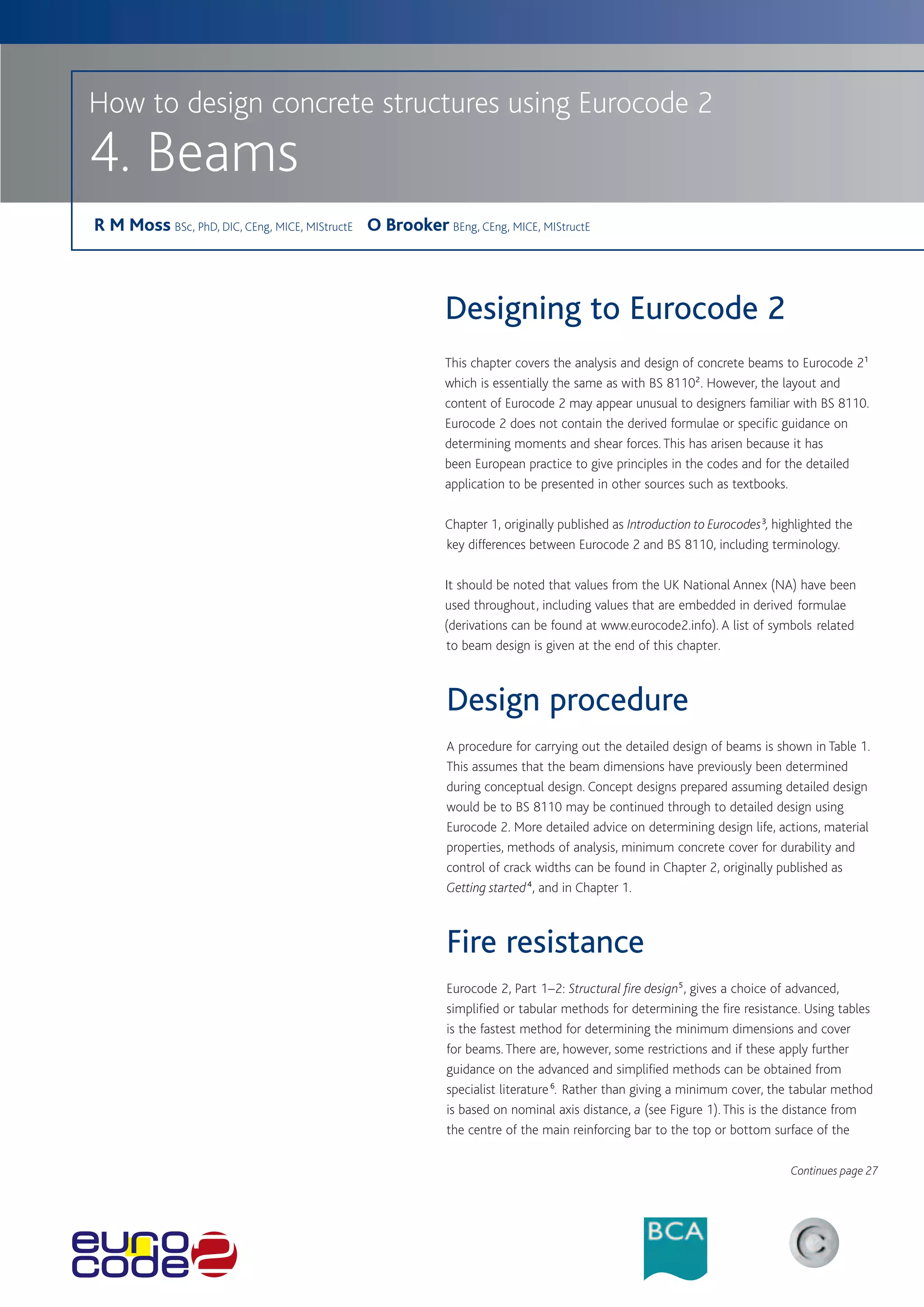
member. It is a nominal (not minimum) dimension, so the designer Procedure for determining flexural reinforcement
should ensure that:
a ≥ cnom + f link + f bar /2 and asd = a + 10 mm START
Table 2 gives the minimum dimensions for beams to meet the
standard fire periods. Carry out analysis of beam to determine
design moments (M) (see Table 3)
Flexure Concrete class No Outside scope of this
≤C50/60? publication
The design procedure for flexural design is given in Figure 2; this includes Yes
derived formulae based on the simplified rectangular stress block from M
Determine K from K =
Eurocode 2. Table 3 may be used to determine bending moments and bd 2 fck
shear forces for beams, provided the notes to the table are observed.
Determine K’ from Table 4 or
Table 3 K’ = 0.60d – 0.18 d2 – 0.21
Bending moment and shear coefficients for beams where d ≤ 1.0
Moment Shear
Outer support 25% of span moment 0.45 (G + Q) No Compression reinforcement
Is K ≤ K ’ ? required
Gl + 0.100 Ql
At first interior support – 0.094 (G + Q) l 0.63 (G + Q)a
Yes
At middle of interior spans 0.066 Gl + 0.086 Ql Calculate lever arm z from
At interior supports – 0.075 (G + Q) l 0.50 (G + Q) z = d 1 + 1 – 3.53 K ’
[ ]
No compression reinforcement required 2
Key
a 0.55 (G + Q) may be used adjacent to the interior span.
Notes
1 Redistribution of support moments by 15% has been included. Obtain lever arm z from Table 5 or use Calculate compression
2 Applicable to 3 or more spans only and where Qk ≤ G k. reinforcement required from
z= d [1 + 1 – 3.53 K ] ≤ 0.95d
3 Minimum span ≥ 0.85 longest span. 2 (K– K’) fck bd 2
As2 =
4 l is the span, G is the total of the ULS permanent actions, Q is the total fsc(d– d2)
of the ULS variable actions.
where
Calculate tension reinforcement
Table 4
Values for K ’
required from
As =
M
fsc = 700
[ x – d2
x ] ≤ fyd
fyd z
% redistribution d (redistribution ratio) K ’
Check minimum reinforcement Calculate tension
requirements (see Table 6) reinforcement required from
0.26 fctm bt d K’fck bd 2 fsc
As,min = where fck ≥ 25 As = + As2
fyk fyd z fyd
Check maximum reinforcement requirements As,max = 0.04 Ac
for tension or compression reinforcement outside lap locations
Key
a
Table 5 Table 6
z/d for singly reinforced rectangular sections Minimum percentage of required reinforcement
K z/d K z/d fck fctm Minimum percentage (0.26 fctm / fyka)
Key Key
a a
3
27](https://image.slidesharecdn.com/howtodesignconcretestructuresusingeurocode2-100408075224-phpapp02/75/How-To-Design-Concrete-Structures-Using-Eurocode-2-31-2048.jpg)
![How to design concrete structures using Eurocode 2
Figure 4
Strut inclination method Eurocode 2 offers various methods for determining the stress-strain
relationship of concrete. For simplicity and familiarity the method
Concrete strut in compression
presented here is the simplified rectangular stress block, which is
similar to that found in BS 8110 (see Figure 3).
Eurocode 2 gives recommendations for the design of concrete up to
y
class C90/105. However, for concrete greater than class C50/60, the
stress block is modified. It is important to note that concrete strength
is based on the cylinder strength and not the cube strength (i.e. for
class C30/37 the cylinder strength ( fck ) is 30 MPa, whereas the cube
Longitudinal Vertical shear strength is 37 MPa).
reinforcement in tension reinforcement
Vertical shear
Figure 5
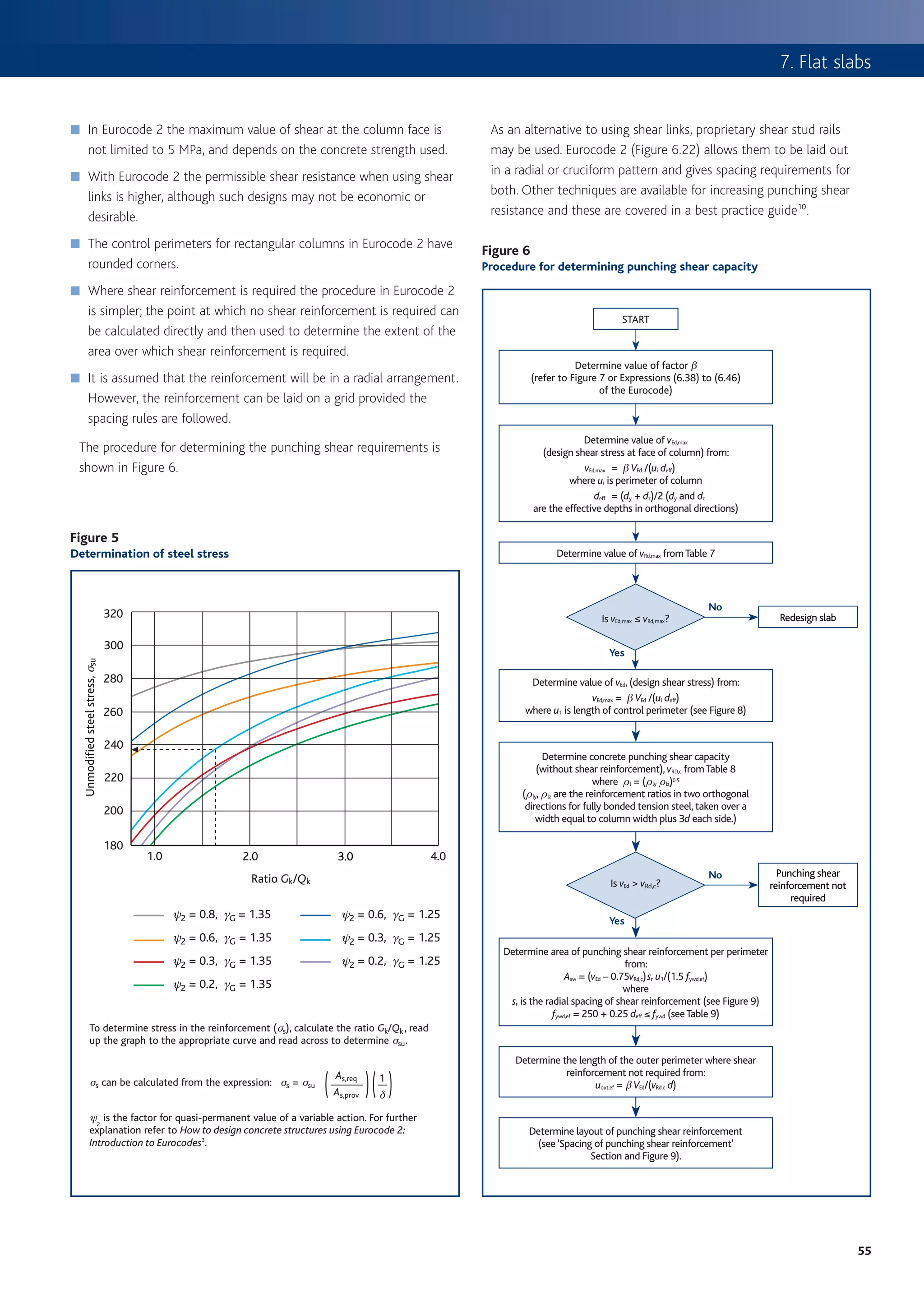
Procedure for determining vertical shear reinforcement Eurocode 2 introduces the strut inclination method for shear capacity
checks. In this method the shear is resisted by concrete struts acting in
START compression and shear reinforcement acting in tension.
Determine vEd where The angle of the concrete strut varies, depending on the shear force
vEd = design shear stress [ vEd = VEd /(bwz) = VEd /(0 9 bwd)]
. applied (see Figure 4). The procedure for determining the shear capacity
of a section is shown in Figure 5 (which includes UK NA values) and is
Determine the concrete strut capacity v Rd, max cot y = 2.5
in terms of shear stress in the vertical plane rather than a vertical force
from Table 7 as given in Eurocode 2. Where shear reinforcement is required, then
the angle of the concrete strut should be calculated. For many typical
beams the minimum angle of strut will apply (when cot y = 2.5 or y =
Is Is
21.8º) i.e. for class C30/37 concrete the strut angle exceeds 21.8º only
No No Redesign
vEd < vRd,max coty = 2.5? v Ed < v Rd,max cot y = 1.0?
section when the shear stress is greater than 3.27 N/mm2 (refer to Table 7).
(see Table 7)
As with BS 8110, there is a maximum permitted shear capacity, vRd,max ,
(when cot y = 1.0 or y = 45º), but this is not restricted to 5 MPa as in
Yes (cot y = 2.5) Yes
BS 8110.
Determine y from:
vEd
y = 0.5 sin -1
0.20 fck (1 – fck /250)
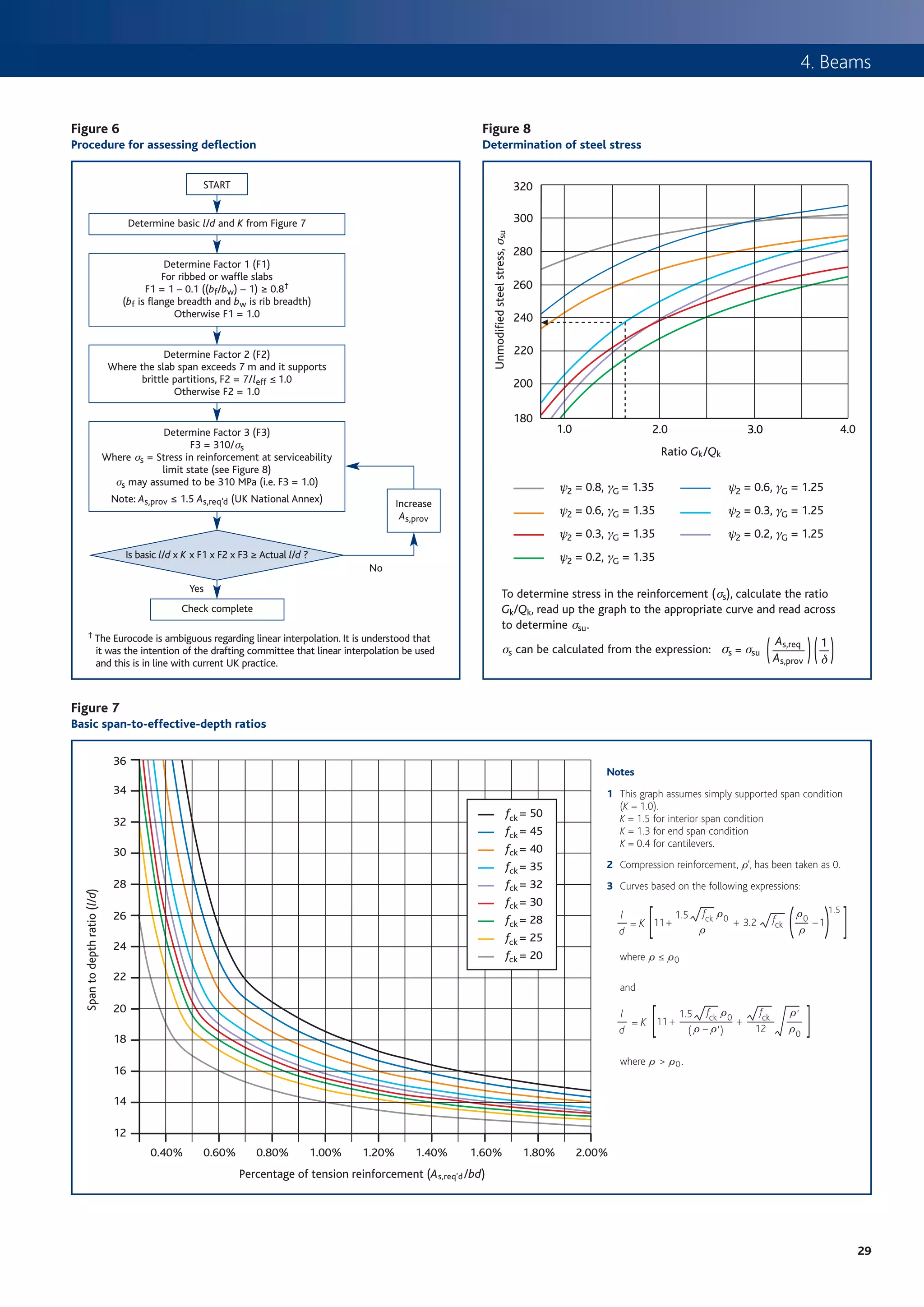
Deflection
Calculate area of shear reinforcement:
Asw vEd bw
=
s fywd cot y
Check maximum spacing for vertical shear reinforcement: 7
s l, max = 0.75 d
Table 7
Minimum and maximum concrete strut capacity in terms of stress
fck
20
v Rd,max cot y = 2.5
2.54
v Rd,max cot y = 1.0
3.68
Flanged beams
25 3.10 4.50
28 3.43 4.97
30 3.64 5.28
32 3.84 5.58
35 4.15 6.02
40 4.63 6.72
45 5.08 7.38
50 5.51 8.00
4
28](https://image.slidesharecdn.com/howtodesignconcretestructuresusingeurocode2-100408075224-phpapp02/75/How-To-Design-Concrete-Structures-Using-Eurocode-2-32-2048.jpg)
![How to design concrete structures using Eurocode 2
Figure 11 Figure 9
Procedure for determining flexural capacity of flanged beams Definition of lo, for calculation of effective flange width
START
l0 = 0.85 l1 l0 = 0.15 (l1 + l2 ) l0 = 0.7 l2 l0 = 0.15 l2 + l3
Carry out analysis of beam to determine design
moments, M (see Table 3)
l1 l2 l3
Determine l0 (see Figure 9) and beff from:
beff = (bw + beff1 + beff2) where Figure 10
beff1 = (0.2b1 + 0.1 l0) ≤ 0.2 l0 ≤ b1 Effective flange width parameters
beff2 = (0.2b2 + 0.1 l0) ≤ 0.2 l0 ≤ b2
Note: The flange width at the support will be beff
different from that at mid-span. beff,1 beff,2
For symbols refer to Figures 9 and 10
bw
M b1 b1 b2 b2
Determine K from K =
bd 2 fck
where b = bw at support b
b = beff in span
Figure 12
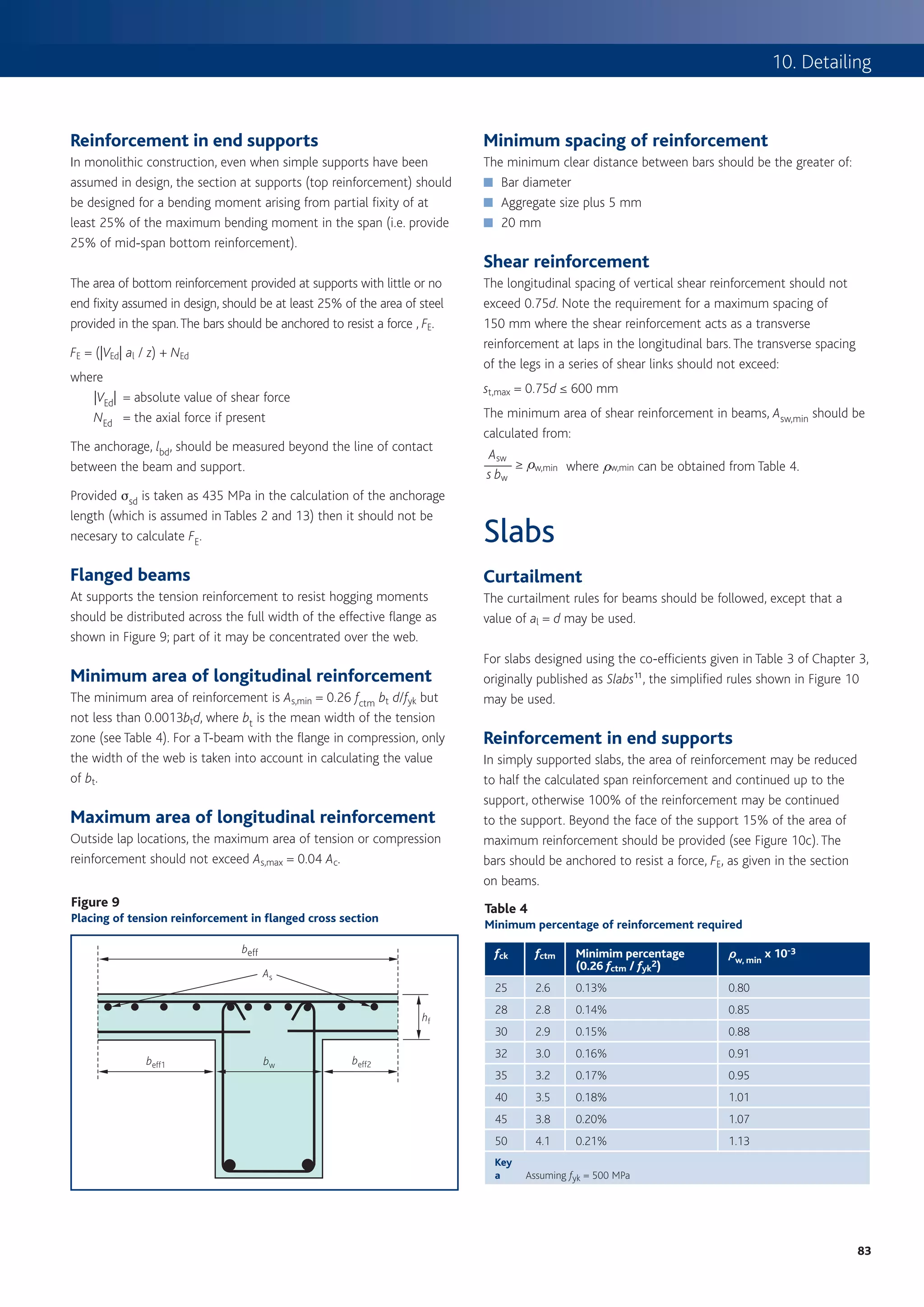
Placing of tension reinforcement in flanged cross section
Determine K’ from Table 4 or
K’ = 0.60d – 0.18 d2 – 0.21 where d ≤ 1.0
beff
As
Calculate lever arm z from
d
z=
2 [1 + 1 – 3.53 K ≤ 0.95d ] hf
Calculate depth to neutral axis x from: beff1 bw beff2
x = 2.5 (d – z)
Neutral axis in
flange. Design
Yes as rectangular
Is x ≤ 1.25hf ? section (Figure 2)
and then check
longitudinal shear
(Figure 14)
No
Figure 13
Neutral axis in web
Calculate moment capacity of flange from:
Notations for the connection between flange and web
MR,f = 0.57 fck (beff – bw) hf (d – 0.5hf)
M – MR,f Fd A
and Kf = yf
fck bw d 2
Compressive struts
Fd beff
Dx
Asf
Sf
No
Is Kf ≤ K ’? Redesign section A hf
Yes Longitudinal bar
anchored beyond Fd + D Fd
this projected point
Calculate area of reinforcement required from Check longitudinal
MR,f M – MR,f shear Fd + D Fd
As = + (see Figure 14) bw
fywd (d – 0.5 hf ) fywd
6
30](https://image.slidesharecdn.com/howtodesignconcretestructuresusingeurocode2-100408075224-phpapp02/75/How-To-Design-Concrete-Structures-Using-Eurocode-2-34-2048.jpg)
![How to design concrete structures using Eurocode 2
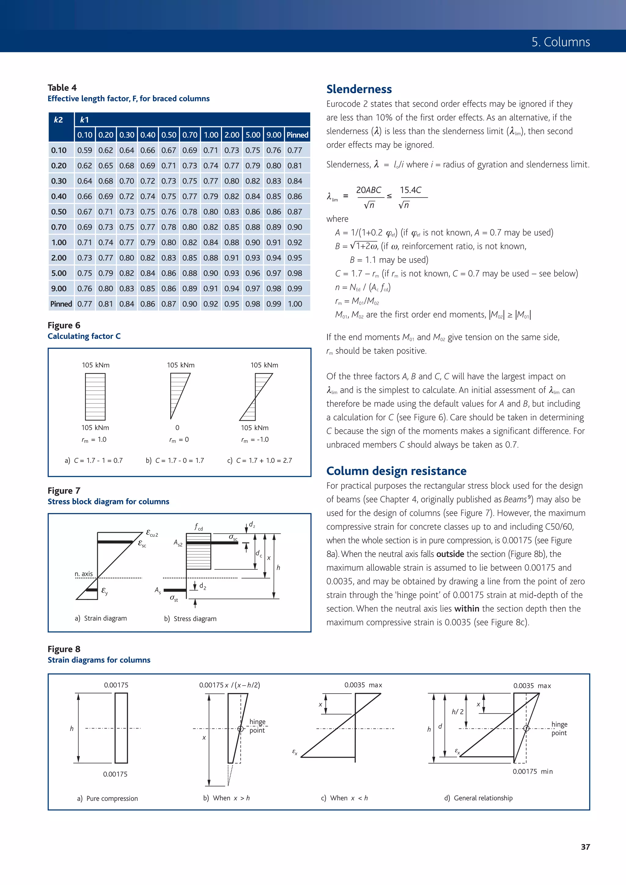
The general relationship is shown in Figure 8d). For concrete classes Creep
above C50/60 the principles are the same but the maximum strain Depending on the assumptions used in the design, it may be necessary
values vary. to determine the effective creep ratio hef (ref. Cl. 3.1.4 & 5.8.4). A
nomogram is provided in the Eurocode (Figure 3.1) for which the
Two expressions can be derived for the area of steel required, (based on cement strength class is required; however, at the design stage it often
a rectangular stress block, see Figure 7) one for the axial loads and the not certain which class applies. Generally, Class R should be assumed.
other for the moments: Where the ground granulated blastfurnace slag (ggbs) exceeds 35%
AsN /2 = (NEd – fcd b dc) / (σsc – σst) of the cement combination or where pulverized fuel ash (pfa) exceeds
where 20% of the cement combination, Class N may be assumed. Where
AsN = Area of reinforcement required to resist axial load ggbs exceeds 65% or where pfa exceeds 35%, Class S may be assumed.
NEd = Axial load
fcd = Design value of concrete compressive strength
σsc (σst) = Stress in compression (and tension) reinforcement Biaxial bending
b = Breadth of section
dc = Effective depth of concrete in compression = lx ≤ h The effects of biaxial bending may be checked using Expression (5.39),
l = 0.8 for ≤ C50/60 which was first developed by Breslaer.
x = Depth to neutral axis MEdz a MEdy a
h = Height of section ( ) + ( ) ≤ 1.0
MRdz MRdy
AsM /2 = [M – fcd b dc(h/2 – dc/2)] / [(h/2–d2) (σsc+σst)] where
where MEdz,y = Design moment in the respective direction including second
AsM = Total area of reinforcement required to resist moment order effects in a slender column
MRdz,y = Moment of resistance in the respective direction
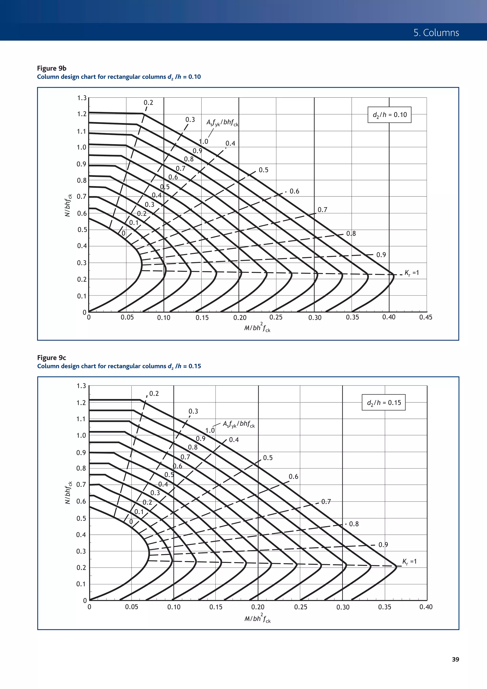
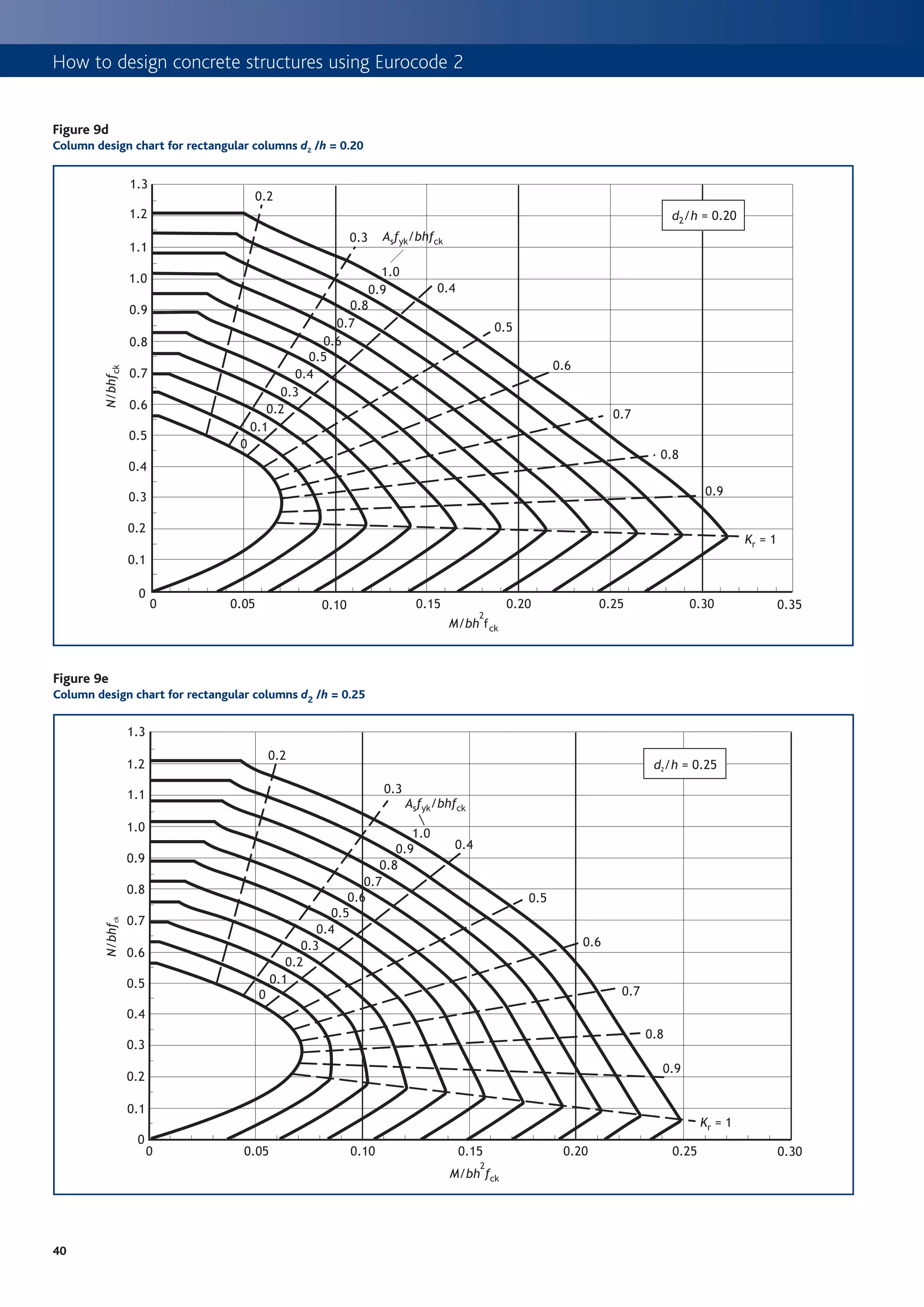
Realistically, these can only be solved iteratively and therefore either a = 2 for circular and elliptical sections; refer to Table 5 for rectangular
computer software (e.g. RC Spreadsheet TCC53 from Spreadsheets for sections
concrete design to BS 8110 and EC27) or column design charts (see NRd = Ac fcd + As fyd
Figures 9a to 9e) may be used. Continues page 41
Figure 9a
Column design chart for rectangular columns d2 /h = 0.05
1.3
Kr = 0.2
1.2 d2/h = 0.05
0.3 Asfyk/bhfck
1.1
1.0 0.4
1.0 0.9
0.8
0.9
0.7 0.5
0.6
0.8
0.5 0.6
0.4
N/bhfck
0.7
0.3
0.7
0.6 0.2
0.1
0.5
0 0.8
0.4
0.9
0.3
1.0
0.2
0.1
0
0 0.05 0.10 0.15 0.20 0.25 0.30 0.35 0.40 0.45
2
M/bh fck
38](https://image.slidesharecdn.com/howtodesignconcretestructuresusingeurocode2-100408075224-phpapp02/75/How-To-Design-Concrete-Structures-Using-Eurocode-2-42-2048.jpg)


![7. Flat slabs
Figure 1 Whichever method of analysis is used, Cl. 9.4.1 requires the designer
Procedure for determining flexural reinforcement to concentrate the reinforcement over the columns. Annex I of the
Eurocode gives recommendations for the equivalent frame method on
START how to apportion the total bending moment across a bay width into
column and middle strips to comply with Cl. 9.4.1. Designers using
Carry out analysis of slab to determine design moments grillage, finite element or yield line methods may also choose to follow
(M) (Where appropriate use coefficients from Table 3).
the advice in Annex I to meet this requirement.
Eurocode 2 offers various methods for determining the stress-strain
No Outside scope of relationship of concrete. For simplicity and familiarity the method
Concrete class
≤C50/60? this publication
presented here is the simplified rectangular stress block (see Figure 2),
which is similar to that found in BS 8110.
Yes
M The Eurocode gives recommendations for the design of concrete up
Determine K from:
Determine K from: K =
bd 2 fck to class C90/105. However, for concrete strength greater than class
C50/60, the stress block is modified. It is important to note that
Determine K’ from Table 4 or concrete strength is based on the cylinder strength and not the cube
K’ = 0.60d – 0.18 d 2 – 0.21 where d ≤ 1.0
strength (i.e. for class C28/35 the cylinder strength is 28 MPa, whereas
the cube strength is 35 MPa).
Compression
No reinforcement Table 4
Is K ≤ K ’ ? required – not Values for K ’
recommended for
typical slabs
% redistribution d (redistribution ratio) K’
Yes 0 1.00 0.208a
10 0.90 0.182a
No compression reinforcement required
15 0.85 0.168
20 0.80 0.153
Obtain lever arm z from Table 5 or 25 0.75 0.137
d 30 0.70 0.120
z=
2 [
1 + 1 – 3.53 K ≤ 0.95d ] Key
a It is often recommended in the UK that K´ should be llimited to 0.168 to ensure
ductile failure
Calculate tension reinforcement required from
M Table 5
As =
fyd z
z/d for singly reinforced rectangular sections
K z/d K z/d
Check minimum reinforcement requirements (see Table 6) ≤ 0.05 0.950a 0.13 0.868
0.26 fctm bt d 0.06 0.944 0.14 0.856
As,min = where fyk ≥ 25
fyk
0.07 0.934 0.15 0.843
0.08 0.924 0.16 0.830
0.09 0.913 0.17 0.816
Check maximum reinforcement requirements.
As,max = 0.04 Ac for tension or compression 0.10 0.902 0.18 0.802
reinforcement outside lap locations 0.11 0.891 0.19 0.787
0.12 0.880 0.20 0.771
Key
a Limiting z to 0.95d is not a requirement of Eurocode 2, but is considered to be good practice
Table 3
Bending moment coefficients for flat slabs
Table 6
End support/slab connection First Interior Interior Minimum percentage of reinforcement required
interior spans supports
Pinned Continuous support fck fctm Minimum % (0.26 fctm /fyka )
End End End End 25 2.6 0.13%
support span support span 28 2.8 0.14%
Moment 0 0.086Fl – 0.04Fl 0.075Fl –0.086Fl 0.063Fl – 0.063Fl 30 2.9 0.15%
32 3.0 0.16%
Notes
35 3.2 0.17%
1 Applicable to slabs where the area of each bay exceeds 30 m2, 40 3.5 0.18%
Qk, ≤ 1.25 Gk and qk ≤ 5 kN/m2
45 3.8 0.20%
2 F is the total design ultimate load, l is the effective span
3 Minimum span > 0.85 longest span, minimum 3 spans
50 4.1 0.21%
4 Based on 20% redistribution at supports and no decrease in span moments Key
a Where fyk = 500 MPa
53](https://image.slidesharecdn.com/howtodesignconcretestructuresusingeurocode2-100408075224-phpapp02/75/How-To-Design-Concrete-Structures-Using-Eurocode-2-57-2048.jpg)
![How to design concrete structures using Eurocode 2
depth ratios are appropriate where the structure remains propped
Deflection during construction or until the concrete attains sufficient strength to
support the construction loads. It can generally be assumed that early
Eurocode 2 has two alternative methods of designing for deflection; striking of formwork will not significantly affect the deflection after
either by limiting span-to-depth ratio or by assessing the theoretical installing the cladding and/or partitions9.
deflection using the Expressions given in the Eurocode. The latter is
dealt with in detail in Chapter 8, originally published as Deflection
calculations 7. Punching shear
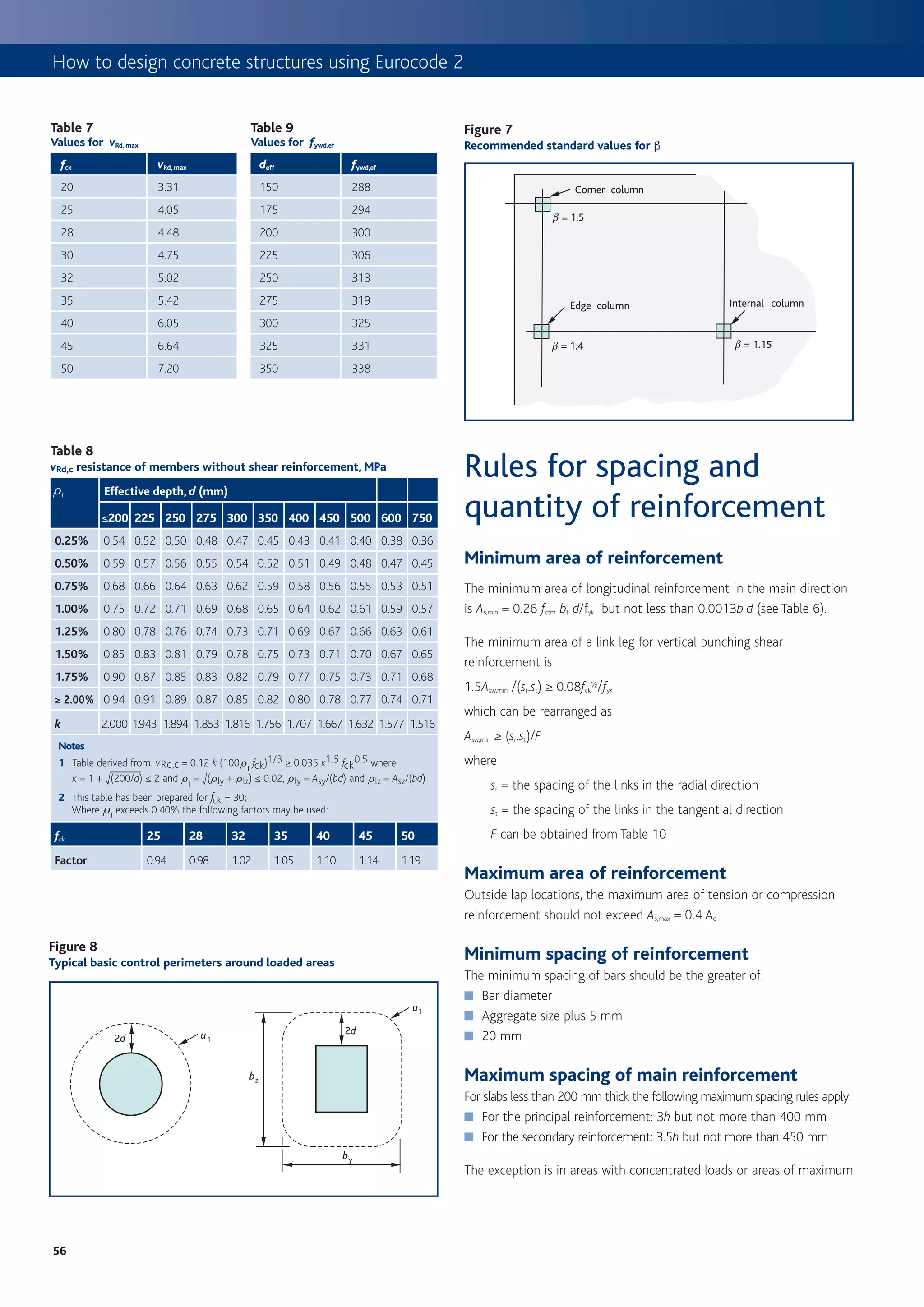
The span-to-depth ratios should ensure that deflection is limited The design value of the punching shear force, VEd, will usually be the
to span/250 and this is the procedure presented in Figure 3. The support reaction at the ultimate limit state. In principle the design
Background paper to the UK National Annex 8 notes that the span-to- for punching shear in Eurocode 2 and BS 8110 is similar. The main
differences are as follows.
Figure 2 ■ Standard factors for edge and corner columns that allow for
Simplified rectangular stress block for concrete up to class C50/60 moment transfer (b) are greater in Eurocode 2. However, b can
from Eurocode 2
be calculated directly from Expressions (6.38) to (6.46) of the
Eurocode to give more efficient designs.
Figure 4
Basic span-to-effective-depth ratios for flat slabs
39
37 fck = 50
Figure 3 fck = 45
Procedure for assessing deflection 35 fck = 40
fck = 35
33 fck = 32
Span-to-effective-depth ratio (l/d)
START fck = 30
31 fck = 28
fck = 25
Determine basic l/d from Figure 4 29 fck = 20
27
Determine Factor 1 (F1)
For ribbed or waffle slabs 25
F1 = 1 – 0.1 ((bf/bw) – 1) ≥ 0.8†
(bf is flange breadth and bw is rib breadth)
Otherwise F1 = 1.0 23
21
Determine Factor 2 (F2)
Where the slab span exceeds 8.5 m and it supports 19
brittle partitions, F2 = 8.5/leff
Otherwise F2 = 1.0 17
15
Determine Factor 3 (F3) 0.40% 0.60% 0.80% 1.00% 1.20% 1.40% 1.60% 1.80% 2.00%
F3 = 310/ss Percentage of tension reinforcement (A s /bd)
Where ss = Stress in reinforcement at serviceability
limit state (see Figure 5)
ss may be assumed to be 310 MPa (i.e. F3 = 1.0)
Notes
Note: As,prov ≤ 1.5 As,req’d (UK National Annex) Increase
1 This graph assumes a simply supported flat slab (K = 1.2).
As,prov
2 Compression reinforcement, r’, has been taken as 0.
Is basic l/d x F1 x F2 x F3 ≥ Actual l/d ? 3 Curves based on the following expressions:
No 1.5
1.5 fck r 0 r0
Yes
l
d [
= K 11 +
r
+ 3.2 fck
( ) ]
r
–1 where r ≤ r 0 and
Check complete
1.5 fck r 0 r’
† The Eurocode is ambiguous regarding linear interpolation. It is understood that this
was the intention of the drafting committee and is in line with current UK practice.
l
d [
= K 11 +
( r – r ’)
+
fck
12 ]
r0
where r > r 0 .
54](https://image.slidesharecdn.com/howtodesignconcretestructuresusingeurocode2-100408075224-phpapp02/75/How-To-Design-Concrete-Structures-Using-Eurocode-2-58-2048.jpg)

![How to design concrete structures using Eurocode 2
any of the earlier load stages. If, however, an earlier stage Figure 3
proves critical, the z value at that stage should be carried Outline of rigorous method for calculating deflection
forward to all subsequent stages.
Collate input data
Further information can be found in the best practice ■ Element dimensions and reinforcement details and arrangements from the
guide Early striking and improved backpropping6. ultimate limit state design
■ Loading sequence e.g.
• Striking the formwork
Shrinkage curvature • Casting the floor above
Shrinkage depends on the water/cement ratio, relative • Erection of the partitions and/or cladding
• Application of finishes
humidity and the size and shape of the member. The effect The sequence will vary from project to project
of shrinkage in an asymmetrically reinforced section is to ■ Concrete properties (see Table 1)
induce a curvature that can lead to significant deflection in • Mean compressive strength (fcm)
shallow members. This effect should be considered in the • Mean tensile strength (fctm or fctm,fl)
• Elastic modulus (Ec28) = 1.05 Ecm
deflection calculations.
■ Critical arrangement of actions
(or repeat the calculations for each arrangement to determine the critical case)
Methods for
Assess whether the element has flexural cracking
calculating deflections ■ Determine the critical load stage at which cracking first occurs.
(See ‘Cracking’ on page 3)
Two methods for calculating deflection are presented ■ Calculate the following properties:
• Creep coefficients, h (Annex B of Eurocode 2 or Figure 4)
below, and these are based on the advice in TR58 • Long term elastic modulus, ELT (see Panel 1)
Deflections in concrete slabs and beams8. • Effective modulus ratio, ae from: ae = Es /ELT
• Neutral axis depth for uncracked condition, xu (see Panel 2)
• Second moment of area for uncracked condition, Iu (see Panel 2)
Rigorous method • Calculate cracking moment, Mcr from:
Mcr = fctm Iu/(h – xu), using appropriate value for fctm.
The rigorous method for calculating deflections is the
■ Does the moment at the critical load stage exceed the cracking moment?
most appropriate method for determining a realistic
• If yes, the element is cracked at all subsequent stages.
estimate of deflection. However, it is only suitable for z = 1 – 0.5(Mcr/M)2 [z = 0 for uncracked situation]
Repeat at 1/20 points for all three loading stages
use with computer software. The Concrete Centre has Use these critical values of fctm and z for subsequent stages.
• If no, the element will not crack at any stage.
produced a number of spreadsheets that use this method
to carry out deflection calculations for a variety of slabs
and beams9. These offer a cost-effective way to carry
Determine the curvature of the slab
out detailed deflection calculations, and they include the
■ When the slab is cracked calculate the following properties at the load stage
ability to consider the effect of early age loading of the being considered, using appropriate values for fctm, z and ELT:
concrete. Figure 3 illustrates the principles of the method • Neutral axis depth for cracked section, xc (see Panel 2)
and shows how the factors affecting deflection are • Second moment of area for cracked condition, Ic (see Panel 2)
considered in the rigorous deflection calculations. ■ Calculate the flexural curvature:
1 MQP MQP
rfl = g E e Ic + ]1 – g g E e Iu
Finite element analysis may also be used to obtain
■ Calculate the curvature due to shrinkage strain 1/rcs (see Panel 2)
estimates of deflection. In this case the principles
■ Calculate the total curvature, 1/rt = 1/rfl + 1/rcs
in Figure 3 should be applied if credible results are to
be obtained.
Repeat the calculations at frequent intervals (say at 1/20 points) and integrate
Panel 1 twice to obtain the overall deflection.
Determining long term elastic modulus of elasticity
Calculate long-term elastic modulus, ELT from: If deflection affecting cladding and/or partitions is required, repeat calculations
for frequent combination and for loading at time of installation of partitions
W1 W2 W3 W4 W5
E LT = RW c + + + + m and/or cladding.
Eeff,1 Eeff, 2 Eeff, 3 Eeff, 4 Eeff, 5
where
Eeff = Ec28/(1+h) Estimate deflections:
■ Overall deflection (quasi-permanent combination)
Wn = Serviceability load at stage n
■ Deflection affecting partitions/cladding (Frequent combination deflection
h = Creep coefficient at relevant loading time
less deflection at time of installation)
and duration
62](https://image.slidesharecdn.com/howtodesignconcretestructuresusingeurocode2-100408075224-phpapp02/75/How-To-Design-Concrete-Structures-Using-Eurocode-2-66-2048.jpg)
![8. Deflection calculations
Table 1
Concrete properties
fck MPa 320 325 328 330 332 335 340 350
fcm = (fck + 8) MPa 328 333 336 338 340 343 348 358
fctm = (0.3 fck(2/3) ≤ C50/60 or 2.12 ln(1 + (fcm/10)) > C50/60) MPa 332.21 332.56 332.77 332.90 333.02 333.21 333.51 334.07
fctm* = (0.3 fcm(2/3) ≤ C50/60 or 1.08 ln(fcm) + 0.1 > C50/60)a MPa 332.77 333.09 333.27 333.39 333.51 333.68 333.96 334.50
Ecm = (22 [(fcm)/10]0.3 GPa 330.0 331.5 332.3 332.8 333.3 334.1 335.2 337.3
Ec28 = (1.05 Ecm) GPa 331.5 333.0 333.9 334.5 335.0 335.8 337.0 339.1
ecd,0 CEM class R, RH = 50% microstrain 746 706 683 668 653 632 598 536
ecd,0 CEM class R, RH = 80% microstrain 416 394 381 372 364 353 334 299
ecd,0 CEM class N, RH = 50% microstrain 544 512 494 482 471 454 428 379
ecd,0 CEM class N, RH = 80% microstrain 303 286 275 269 263 253 239 212
ecd,0 CEM class S, RH = 50% microstrain 441 413 397 387 377 363 340 298
ecd,0 CEM class S, RH = 80% microstrain 246 230 221 216 210 202 189 166
eca(∞) microstrain 325 338 345 350 355 363 375 100
Key
a fctm* may be used when striking at less than 7 days or where construction overload is taken into account.
Panel 2
Useful Expressions for a rectangular section
bh 2 where
2 + ] ae - 1 g ] Asd + As2 d2 g
xu = As = Area of tension reinforcement
bh + ] ae - 1 g ] As + As2 g
As2 = Area of compression reinforcement
bh 3 2 b = Breadth of section
I u = 12 + bh a 2 - xuk + ] ae - 1 g 6 As ]d - xu g + As2 ] x u - d 2 g @
h 2 2
d = Effective depth to tension
reinforcement
xc = # 7 ^ As ae + A s2 ] ae - 1 g h 2+ 2 b ^ As d ae + A s2d2 ] ae - 1 g h A 0.5- ^ As ae + As2 ] ae - 1 g h - b
d2 = Depth to compression reinforcement
h = Overall depth of section
3
bx c ae = Modular ratio
I c = 3 + ae As ^ d - x c g + ^ ae - 1 g As2 ^ d2 - x c g
2 2
Su = As(d – xu) – As2 (xu – d2)
1 Su Sc Sc = As(d – xc) – As2 (xc – d2)
rcs = g f cs a e I u +^1 - g h fcs ae I c
Figure 4
Method for determining creep coefficient h(∞,t0)
1 1
S N R S N R
2 2
3 3
5 5
t 0 10 t 0 10
20 20
30 30
50 50
100 100
7.0 6.0 5.0 4.0 3.0 2.0 1.0 0 100 300 500 700 900 1100 1300 7.0 6.0 5.0 4.0 3.0 2.0 1.0 0 100 300 500 700 900 1100 1300
h (?, t 0 ) h 0 (mm) h (?, t 0) h o (mm)
a) Inside conditions - RH = 50% b) Outside conditions - RH = 80%
How to use Nonogram
Ke y Notes
C20/25 C40/50 1 t0 = age of concrete at time of loading
D
C25/30 C45/55 2 h0 = 2A c /u A
C30/37 C50/60 3 Intersection point between lines D & E can also be above point A E C
B
C35/45 4 For t0 > 100 it is sufficiently accurate to assume t = 100
63](https://image.slidesharecdn.com/howtodesignconcretestructuresusingeurocode2-100408075224-phpapp02/75/How-To-Design-Concrete-Structures-Using-Eurocode-2-67-2048.jpg)
![How to design concrete structures using Eurocode 2
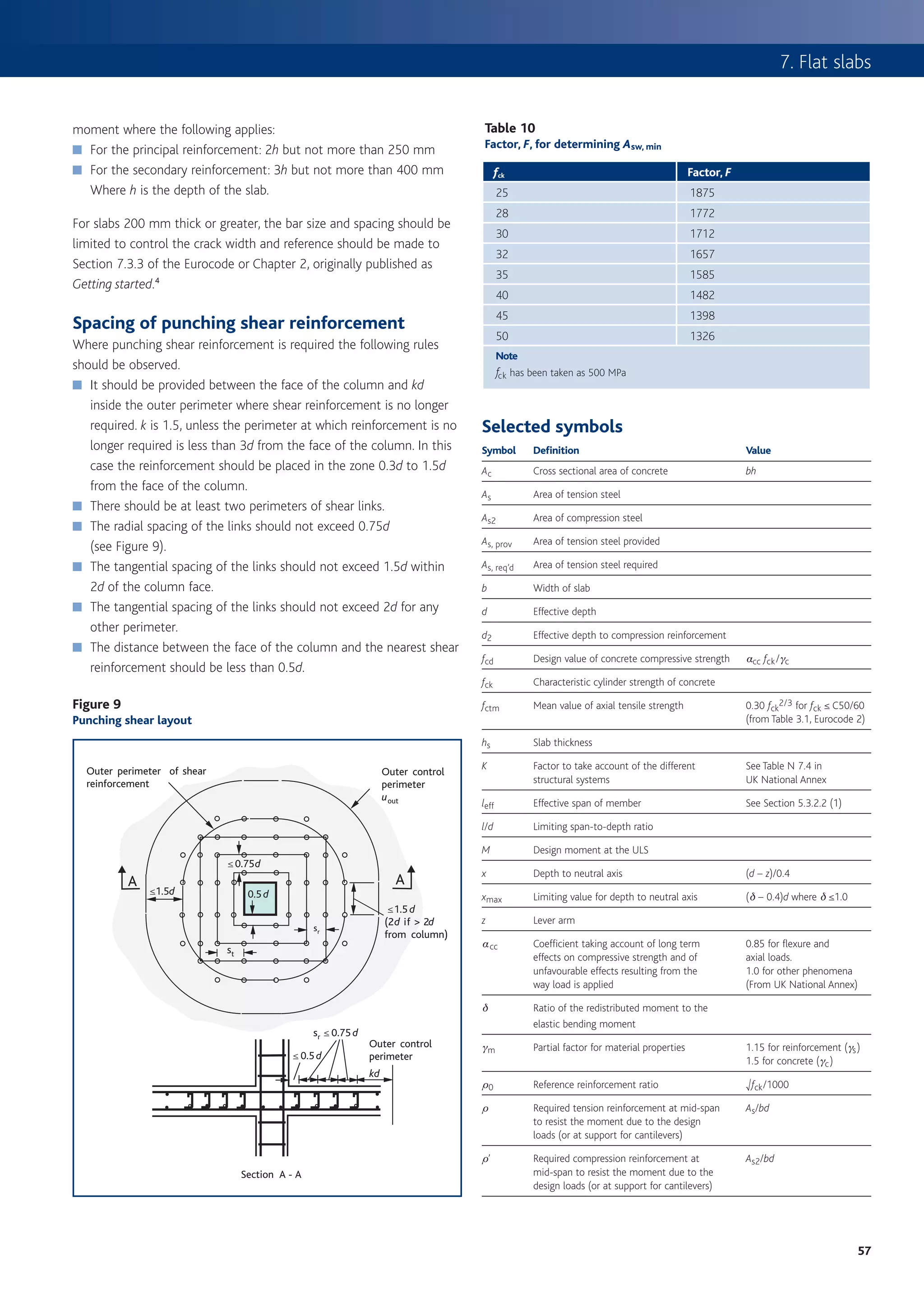
Simplified method Figure 5
Simplified method for calculating deflection
A simplified method for calculating deflection is presented in Figure 5.
It is feasible to carry out these calculations by hand, and they could be
START
used to roughly verify deflection results from computer software, or
used where a computer is not available. Calculate the moment, MQP, due to quasi-permanent actions at
the critical section (i.e. mid-span or at support for cantilever)
The major simplification is that the effects of early age loading are not Obtain concrete properties, fctm, and Ec28 from Table 1
considered explicitly; rather an allowance is made for their effect when
calculating the cracking moment. Simplified creep factors are used and Calculate creep coefficient, h(∞,t0), using either Figure 4
or Annex B (in which case look-up fcm in Table 1)
deflection from the curvature of the slab is approximated using a factor.
1 Calculate long term elastic modulus, Eeff from: Eeff = Ec28/[1+h (∞,t0)]
Figure 6 2 Calculate effective modulus ratio, ae from ae = Es/Eeff, where Es is
elastic modulus for reinforcement (200 GPa)
Values for K for various bending moment diagrams
3 Calculate depth to neutral axis for uncracked condition, xu
4 Calculate second moment of area for uncracked condition, Iu
Loading Bending moment diagram K
0.9 fctm I u
0.125 Calculate cracking moment, Mcr from: Mcr =
M h – xu
M M (Note the factor 0.9 has been introduced into this method
because the loading sequence is not considered)
al W 3 4a 2 Yes No
48 (1-a)
Is Mcr > MQP?
l M = Wa (1-a ) l If a = 1 , K = 1
2 12
Section is uncracked Section is cracked
0.0625 z=0 z = 1 – 0.5(Mcr/MQP)2
M Calculate depth to neutral axis for cracked
condition, xc and calculate second moment of area
for cracked condition, Ic
W/2 W/2
a2
al al 0.125
6
Wal 1 MQP MQP
M= Calculate flexural curvature
rn
= g
Eeff Ic
+ ^1 – g h E
2 eff Iu
q 0.104 Calculate total shrinkage strain ecs from ecs = ecd + eca where:
ecd = kh ecd,0 = Drying shrinkage strain
ql 2 kh = Coefficient based on notional size, see Table 2
8 ecd,0 = Nominal unrestrained drying shrinkage, see Table 1
eca = bas(t) eca(∞) = eca(∞) for long-term deflection, see Table 1
q 0.102
Calculate curvature due to shrinkage strain 1/rcs (see Panel 2)
ql 2
15.6
1 1 1
Calculate total curvature r = rn + rcs
t,QP
b
q MA MC MB K = 0.104 (1 )
10 1
MA + MB Calculate quasi-permanent deflection from dQP KL 2 rt,QP=
b=
MC where K can be obtained from Figure 6 and L is the span.
al W End deflection
Wal
a (3 a ) Do you need No
= to calculate deflection
6 Finish
load at end K = 0.333 due to cladding and
partitions?
Yes
2 2
al qa l a (4 a )
q 2 12 Calculate the deflection that will occur at the time of application of
the load due to partitions and/or cladding.
if a = l , K = 0.25
1 Calculate the creep coefficient h(t,t0), where t is the age when
partition/cladding loads are applied and t0 is the age of striking.
b h(t,t0) ≈ h(∞,t0) bc(t,t0). For bc(t,t0) refer to Figure 7, alternatively
MA MB K = 0.083 (1 ) refer to Annex B of Eurocode 2.
4
MA + MB 2 Calculate the moment due to self-weight, partitions/cladding and any
MC b= other loads which have been applied prior to the installation of the
MC
cladding/partition, Mpar and use in place of MQP
al al 3 Recalculate the section properties, curvature and hence deflection,
1 (5 4a 2 )
2 dpar, using h(t,t0) or equivalent instead of h(∞,t0)
2
Wl (3 4a 2) 80 3 4a 4 The approximate deflection affecting cladding and partitions is
24 d = dQP – dpar
64](https://image.slidesharecdn.com/howtodesignconcretestructuresusingeurocode2-100408075224-phpapp02/75/How-To-Design-Concrete-Structures-Using-Eurocode-2-68-2048.jpg)

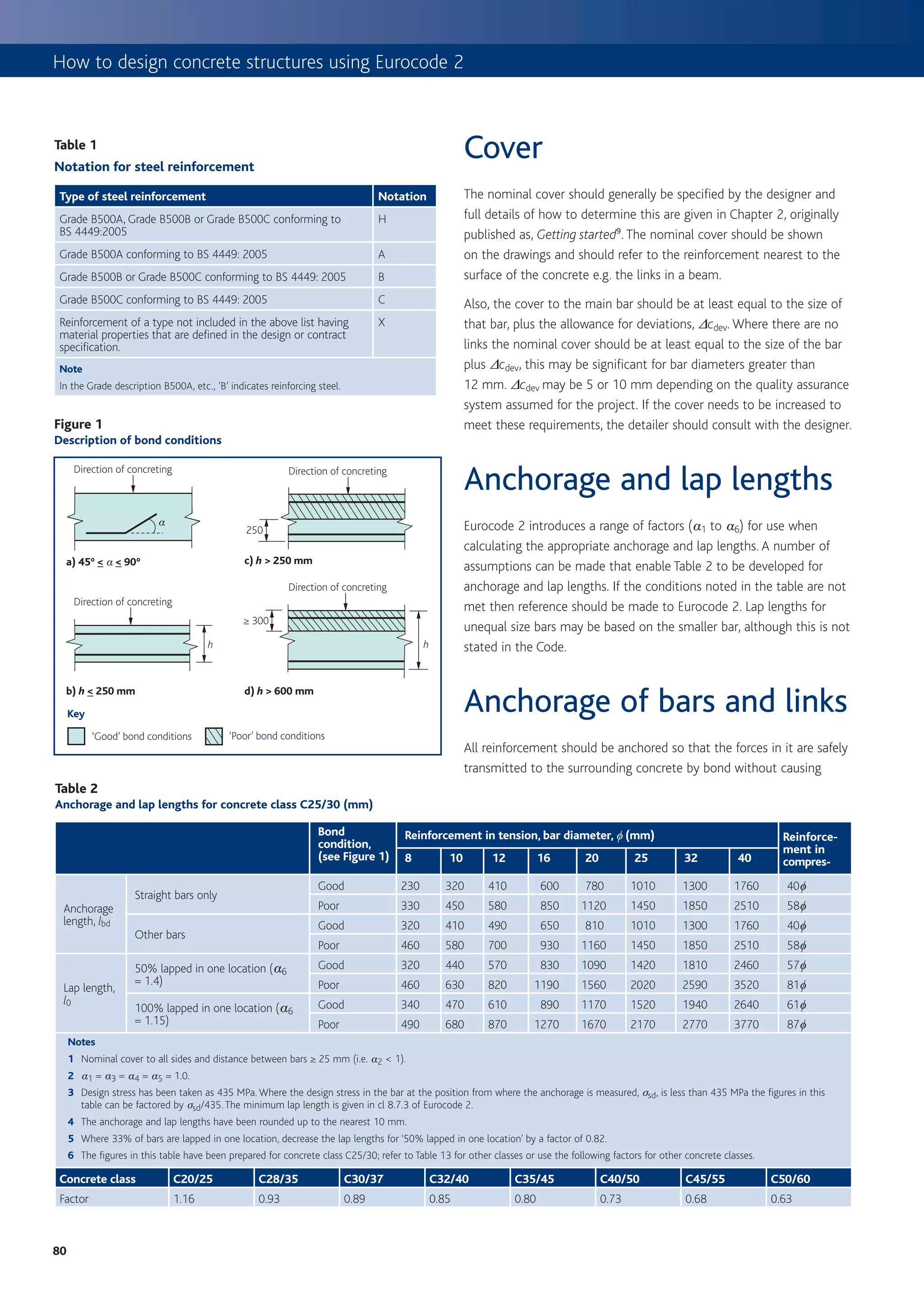
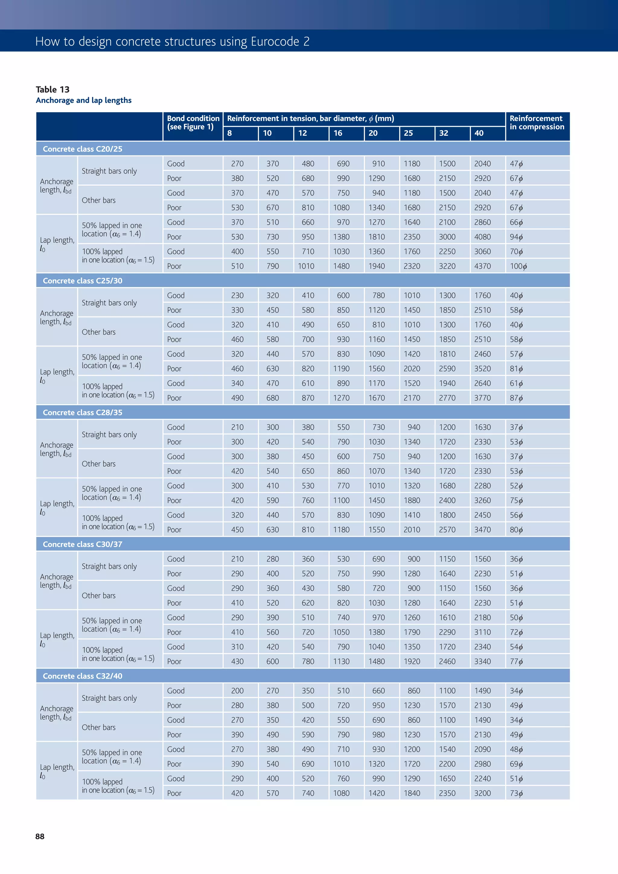
(Ft) ≥ Ft kN/m
32 112 305 465
where
40 140 580
(qk + gk) = sum of the average permanent and variable floor loads Key
(in kN/m2) a The minimum end projections for smaller bars is governed by the practicalities of
bending bars.
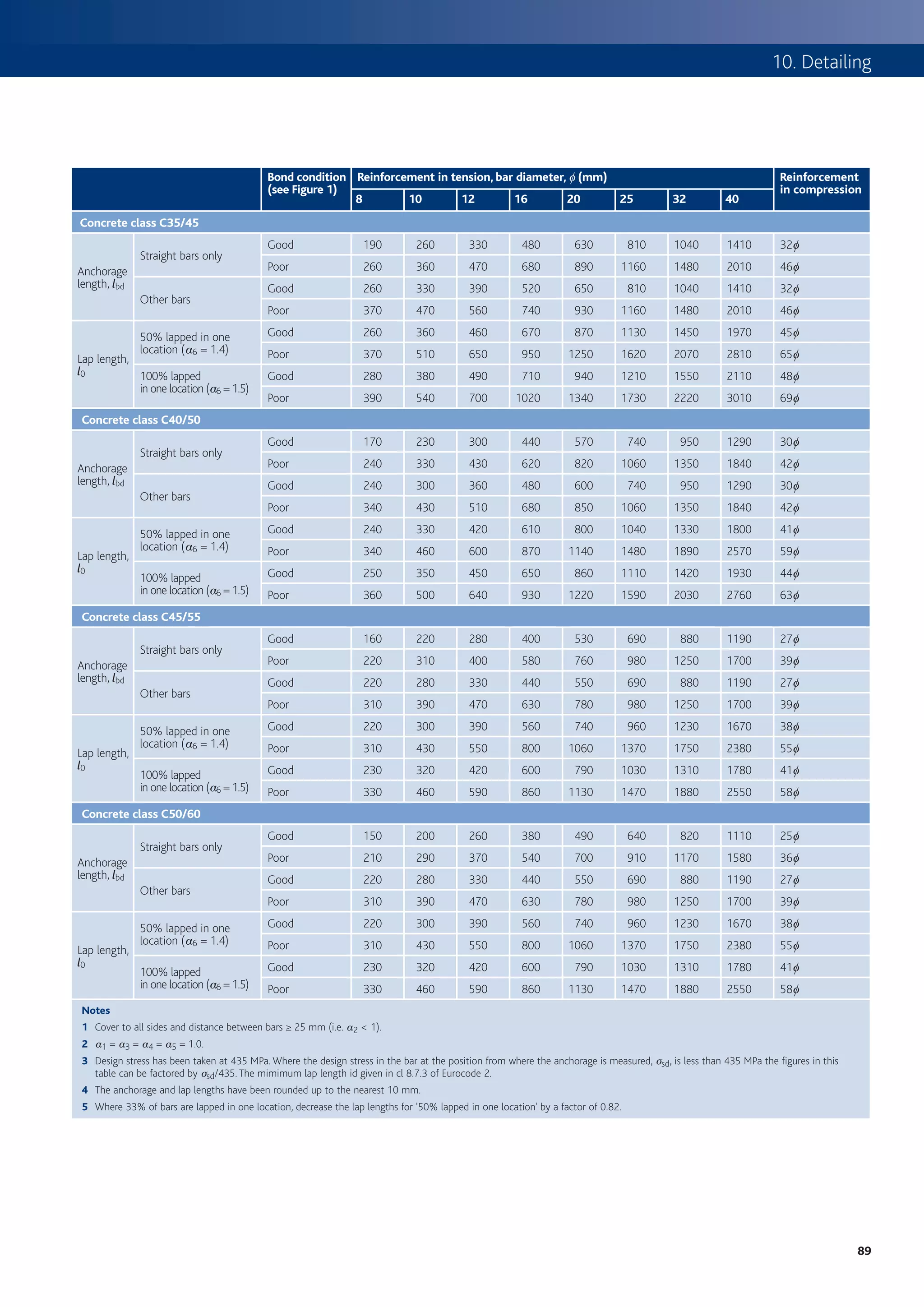
References
1 BRITISH STANDARDS INSTITUTION. BS EN 1992, Eurocode 2: Design of concrete structures. BSI (4 parts).
2 BRITISH STANDARDS INSTITUTION. BS 8500: Concrete – Complementary standard to BS EN 206–1. BS1, 2002.
3 BRITISH STANDARDS INSTITUTION. BS 4449: Specification for carbon steel bars for the reinforcement of concrete. BSI, 2005.
4 BRITISH STANDARDS INSTITUTION. BS EN 10080: Steel for the reinforcement of concrete – Weldable reinforcing steel – General. BSI, 2005.
5 BRITISH STANDARDS INSTITUTION. BS 8666: Scheduling, dimensioning, bending and cutting of steel reinforcement for concrete – Specification. BSI, 2005.
6 INSTITUTION OF STRUCTURAL ENGINEERS/CONCRETE SOCIETY. Standard method of detailing structural concrete. ISE/CS, 2006.
7 CONSTRUCT. National structural concrete specification (third edition). BCA, 2004.
8 CONSTRUCT. A guide to contractor detailing of reinforcement in concrete. BCA, 1997.
9 BROOKER, O. How to design concrete structures using Eurocode 2: Getting started. The Concrete Centre, 2006.
10 MOSS, R M & BROOKER, O. How to design concrete structures using Eurocode 2: Beams. The Concrete Centre, 2006.
11 MOSS, R M & BROOKER, O. How to design concrete structures using Eurocode 2: Slabs. The Concrete Centre, 2006.
12 THE CONCRETE SOCIETY. Technical report 62: Self-compacting concrete. CCIP–001. The Concrete Society, 2005.
13 QUEENS PRINTER OF ACTS OF PARLIAMENT. The Construction (Design and Management) Regulations. 1994. QPOAP, 1994.
87](https://image.slidesharecdn.com/howtodesignconcretestructuresusingeurocode2-100408075224-phpapp02/75/How-To-Design-Concrete-Structures-Using-Eurocode-2-91-2048.jpg)


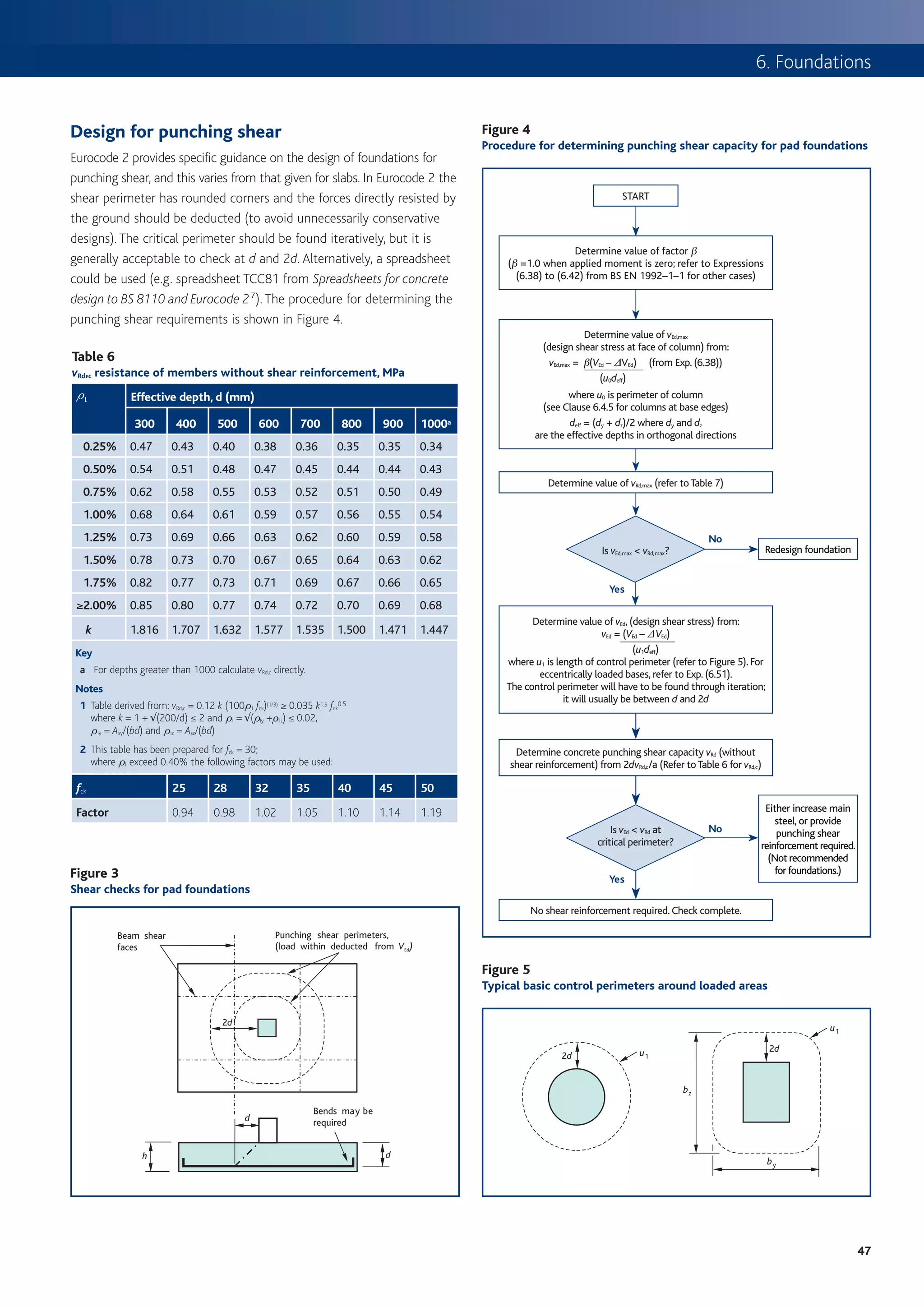
This document provides an introduction to using Eurocode 2 (EC2) for designing concrete structures. Some key points: 1. EC2 is part of a family of Eurocodes that will replace existing national standards for structural design across Europe, including BS 8110 in the UK. 2. EC2 takes a statistical approach to determining design values for actions (loads) on structures using characteristic, combination, frequent and quasi-permanent values. 3. Load combinations in EC2 consider multiple variable actions and are determined based on the design situation and type of limit state being assessed. 4. EC2 represents a more technical and less restrictive approach than BS 8110, aiming for more economic yet safe concrete structure