Downloaded 14 times
![Introduction
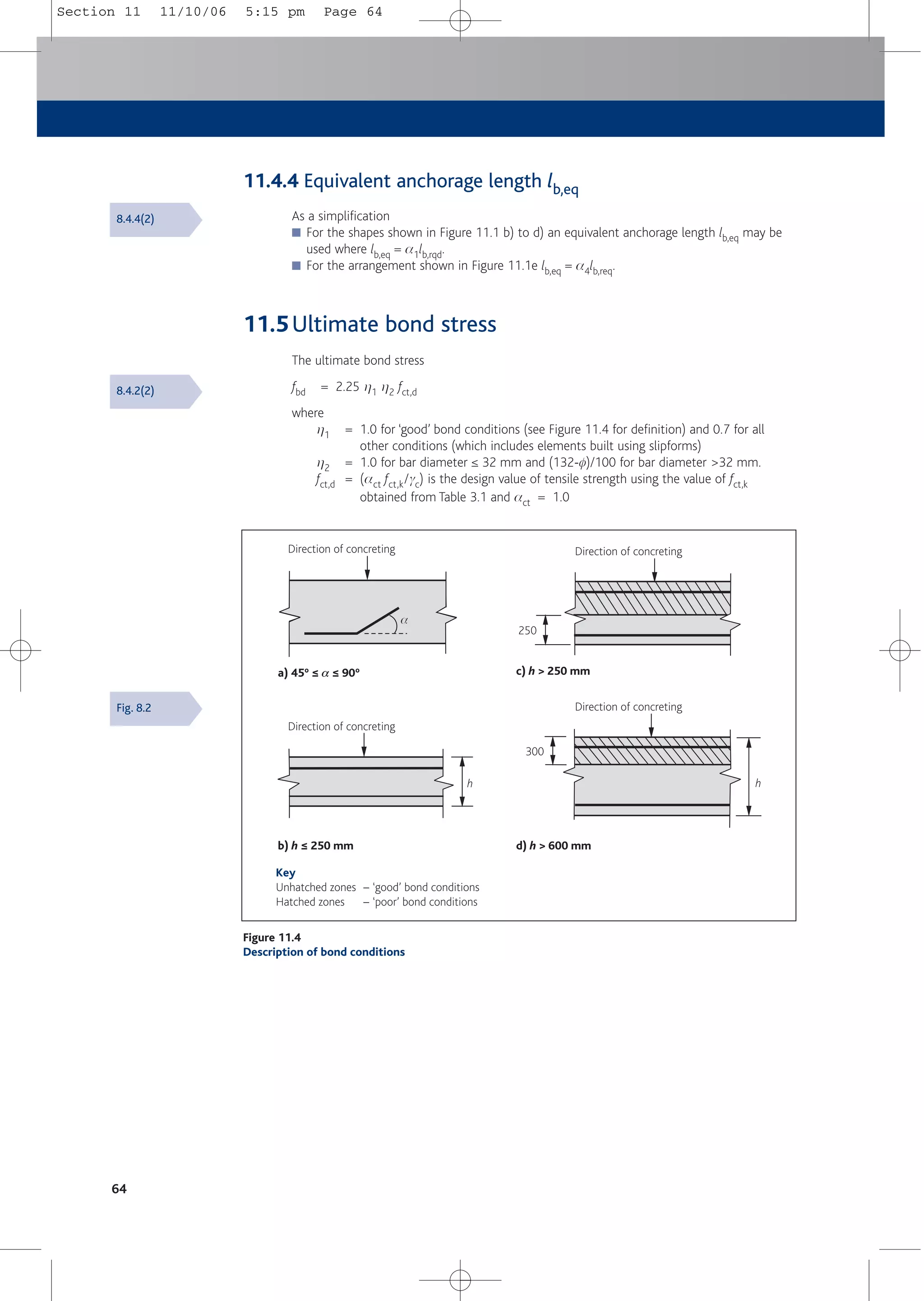
1
1 Introduction
BS EN 1992-1-1 (Eurocode 2: Design of concrete structures Part 1-1[1]) sets out general rules for
the design of concrete structures and rules for the design of buildings. It necessarily covers a
wide spectrum of structures and, therefore, may be seen as unduly complex for routine design
work.
The aim of this Concise Eurocode 2 is to distil from all relevant parts of BS EN 1992 and the
UK National Annexes [1-4] material that will be commonly used in the design of normal building
structures.Thus this publication limits itself to concrete grades up to and including C50/60 and
does not cover prestressed or lightweight concrete. Even with these restrictions, it is believed
that the vast majority of day-to-day designs will fall within its scope.
As far as possible, the Eurocode clauses are repeated verbatim – unless clarity demands
rewording or, in some cases (as identified by grey shading) additional text, derived formulae,
tables, charts and illustrations. This applies particularly to Section 15 and the Appendix. If
relevant, other European Codes and/or British Standards are cited. Cross references to clause
numbers in Eurocode 2 or other Eurocodes are signposted in arrow boxes for quick
identification.
Recognising each member state’s responsibility for determining matters such as safety and
current practice. The Eurocode system permits individual countries to set their own values for
some construction parameters used within their jurisdiction. These values are referred to as
Nationally Determined Parameters (NDPs) and are published as part of that country’s National
Annex.This Concise Eurocode 2 uses the NDPs in the UK National Annex to BS EN 1992-1-1[1a],
and these too are highlighted in arrow boxes.
Generally the flow of information is presented in the same order as in Eurocode 2. However, all
structural design is required to comply with BS EN 1990 (Eurocode: Basis of structural design[5])
which provides information applicable to construction in any material. The relevant basic
information from BS EN 1990 is presented in Section 2. Also, some of the commonly needed
design charts and tables derived for UK practice are provided in Section 15.
Based on the latest available information, this publication is all that engineers will need for the
majority of concrete structures.
Guide to presentation
Grey shaded text, Additional text, derived formulae, tables and illustrations not
tables and figures from Eurocode 2
Relevant clauses or figure numbers from Eurocode 2-1-1 (if the
reference is to other parts, other Eurocodes or other documents
this will be indicated)
From the relevant UK National Annex (generally to
Eurocode 2-1-1)
From both Eurocode 2-1-1 and UK National Annex
Relevant parts of this publication
6.4.4
NA
6.4.4
NA
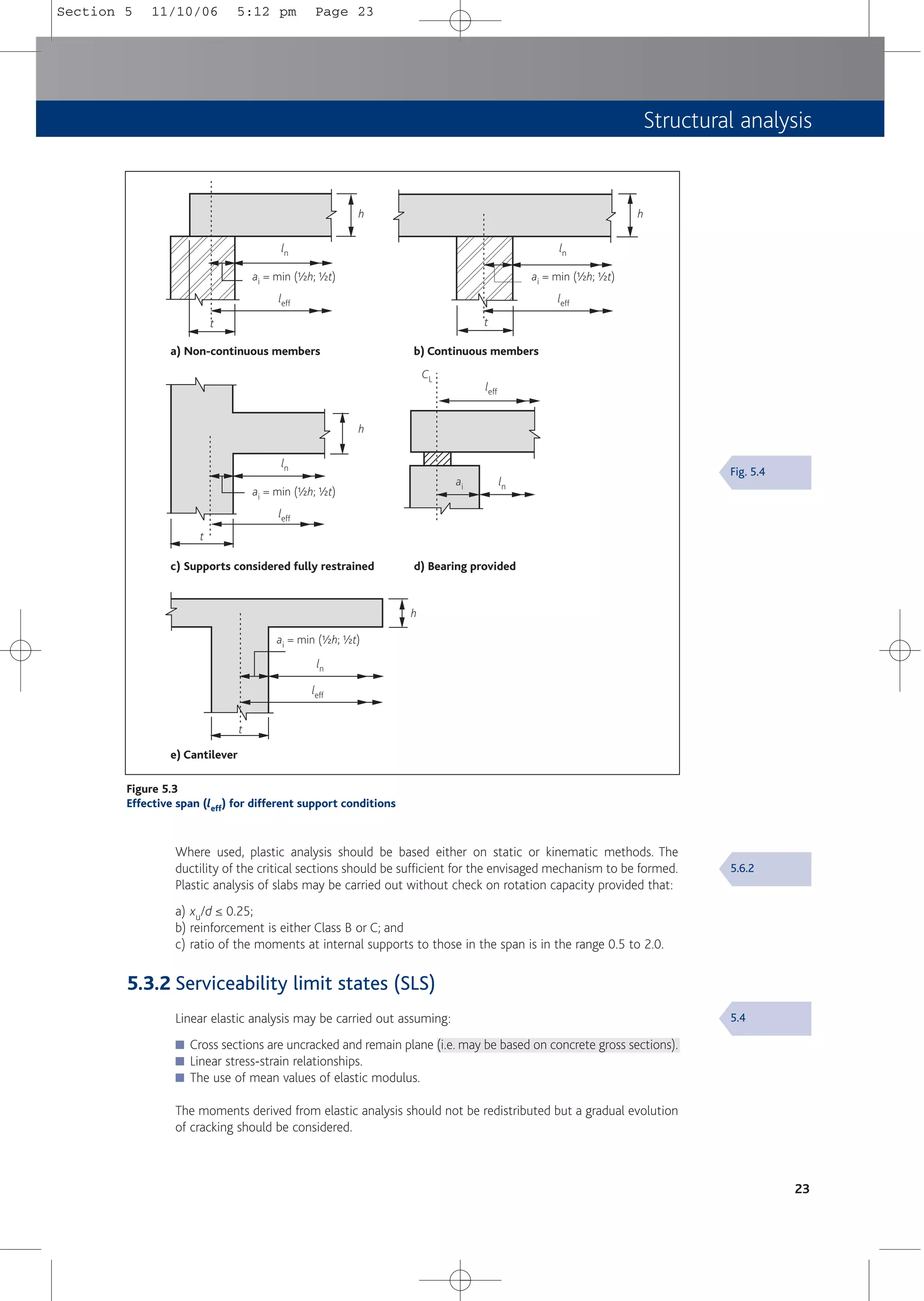
Section 5.2
Section 1 11/10/06 5:09 pm Page 1](https://image.slidesharecdn.com/conciseeurocode2-220718034157-f2f98aab/75/Concise_Eurocode_2-pdf-11-2048.jpg)
![2
2 Basis of design
2.1 General
BS EN 1992-1-1[1] should be used in conjunction with BS EN 1990: Basis of structural design[5],
which:
■ Establishes principles and requirements for the safety, serviceability and durability of
structures.
■ Describes the basis for their design and verification.
■ Gives guidelines for related aspects of structural reliability.
2.2 Basic requirements
2.2.1 General
A structure shall be designed and executed (constructed) in such a way that it will, during its
intended life, with appropriate degrees of reliability and in an economical way:
■ Sustain all actions and influences likely to occur during execution and use.
■ Remain fit for the use for which it is required.
It shall be designed to have adequate stability, structural resistance, serviceability and durability.
In the case of fire, the structural resistance shall be adequate for the required period of time.
A structure shall be designed and executed in such a way that it will not be damaged by events
such as explosion, impact and the consequences of human errors, to an extent disproportionate
to the original cause.
2.2.2 Avoidance of damage
Potential damage shall be avoided or limited by appropriate choice of one or more of the
following:
■ Avoiding, eliminating or reducing the hazards to which the structure can be subjected.
■ Selecting a structural form which has low sensitivity to the hazards considered.
■ Selecting a structural form and design that can survive adequately the accidental removal
of an individual structural member or a limited part of the structure or the occurrence of
localised damage.
■ Avoiding as far as possible structural systems that can collapse without warning.
■ Tying the structural members together.
2.2.3 Limit states principles
BS EN 1990 implies that the design should be verified using limit states principles.
An indicative value of 50 years is given for the design working life of building structures and
other common structures.
BS EN 1990[5]:
2.1
BS EN 1990:
2.1 (5)
BS EN 1990:
2.2 (1)
BS EN 1990:
2.3
Section 2 11/10/06 5:10 pm Page 2](https://image.slidesharecdn.com/conciseeurocode2-220718034157-f2f98aab/75/Concise_Eurocode_2-pdf-12-2048.jpg)
![Basis of design
2.3 Limit state design
Limit states are states beyond which the structure no longer fulfils the relevant design criteria:
■ Ultimate limit states (ULS) are associated with collapse or other forms of structural failure.
■ Serviceability limit states (SLS) correspond to conditions beyond which specified service
requirements are no longer met.
Limit states should be verified in all relevant design situations selected, taking into account the
circumstances under which the structure is required to fulfil its function.
2.3.1 Design situations
Normally, in non-seismic zones, the following design situations should be considered:
■ Persistent situations which refer to the conditions of normal use.
■ Transient situations which refer to temporary conditions, such as during execution or
repair.
■ Accidental situations which refer to exceptional conditions applicable to the structure or to
its exposure (e.g. fire, explosion, impact or the consequences of localised failure).
2.3.2 Actions
Actions refer to loads applied to the structure directly or to imposed deformations, such as
uneven settlements or temperature effects, which induce internal forces in the structure.
■ Permanent actions refer to actions for which the variation in magnitude with time is
negligible.
■ Variable actions are actions for which the variation in magnitude with time is not
negligible.
■ Accidental actions are actions of short duration but of significant magnitude that are
unlikely to occur on a given structure during the design working life.
The characteristic value of an action is defined by one of the following three alternatives.
■ Its mean value – generally used for permanent actions.
■ An upper value with an intended probability of not being exceeded or lower value with an
intended probability of being achieved – normally used for variable action with known
statistical distributions, such as wind or snow.
■ A nominal value – used for some variable and accidental actions.
The values of action given in the various parts of BS EN 1991: Actions on structures[6] are taken
as characteristic values.
2.3.3 Verification
Verification, using the partial factor method, is detailed in BS EN 1990[5]. In this method it is
verified that, in all relevant design situations, no relevant limit state is exceeded when design
values for actions and resistances are used in the design models.
3
BS EN 1990:
3.1
BS EN 1990:
3.2
BS EN 1990:
1.5
BS EN 1990:
4.1.1
BS EN 1990:
4.1.2
BS EN 1991[6]
Section 2 11/10/06 5:10 pm Page 3](https://image.slidesharecdn.com/conciseeurocode2-220718034157-f2f98aab/75/Concise_Eurocode_2-pdf-13-2048.jpg)
![2.3.4 Design values of actions
The design value of an action is gFyFk
where
y = a factor that converts the characteristic value of an action into a representative
value. It adjusts the value of the action to account for the joint probability of
the actions occurring simultaneously and can assume the values equal to:
1.0 for a permanent action
y0 or y1 or y2 for a variable action when it occurs simultaneously
with other variable actions. See Tables 2.1 and 2.2 which are derived
from BS EN 1990 and its National Annex [5a].
gF = partial factor for the action (see Table 2.2)
yFk may be considered as the representative action, Frep, appropriate to the limit state being
considered.
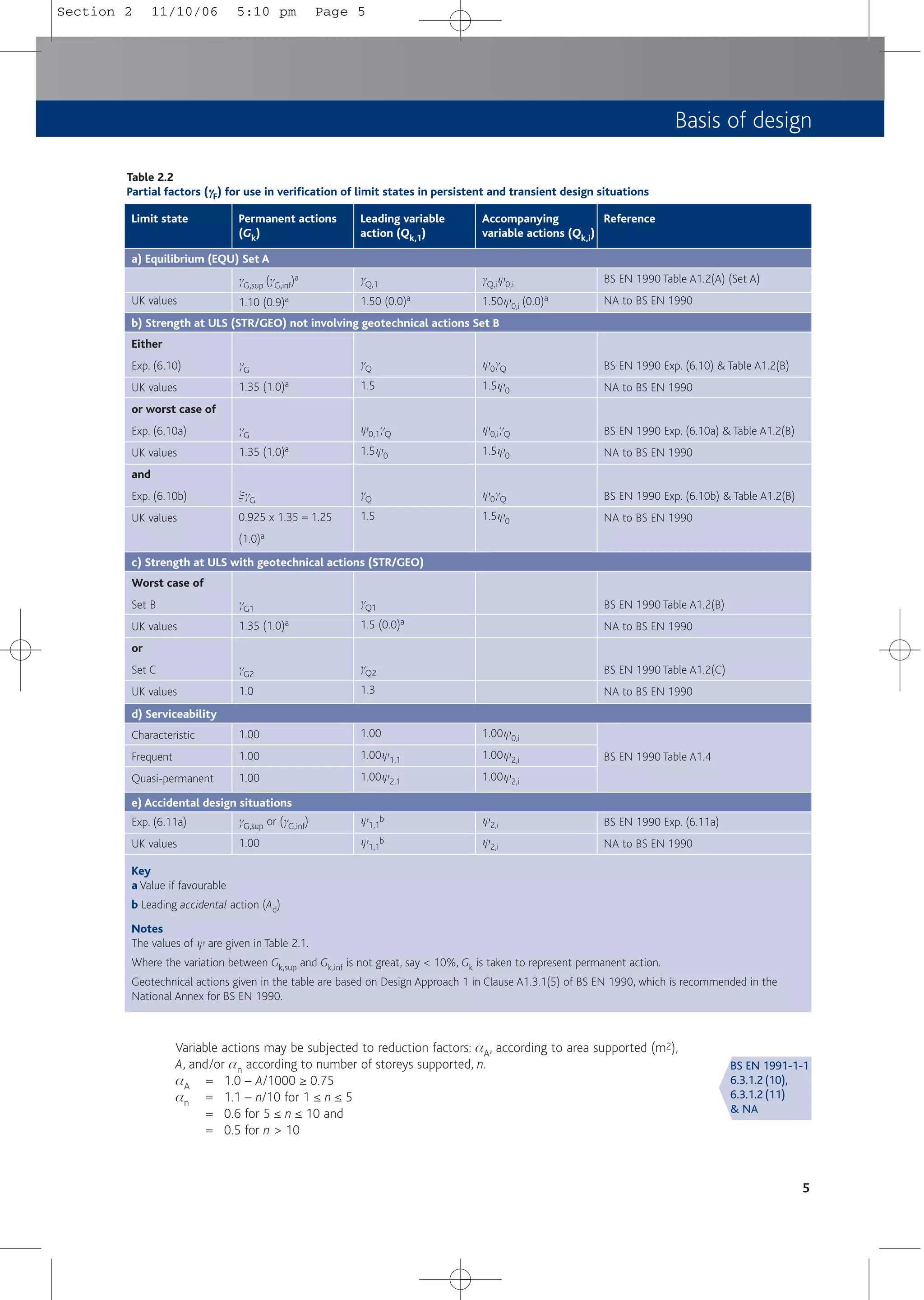
Table 2.2 indicates the partial factors to be used for the combinations of representative actions
in building structures. Table 2.1 shows how characteristic values of variable actions are
converted into representative values.
For the ULS of strength, the designer may choose between using Exp. (6.10) or the less
favourable of Exps. (6.10a) and (6.10b). Exp. (6.10) leads to the use of gF = gG = 1.35 for
permanent actions and gF = gQ = 1.50 for variable actions (gG for permanent actions is intended
to be constant across all spans). Exp. (6.10) is always equal to or more conservative than the
least favourable of Exps. (6.10a) and (6.10b).
Except in the case of concrete structures supporting storage loads where y0 = 1.0, or for
mixed use, Exp. (6.10b) will usually apply. Thus gF = gG = 1.25 for permanent actions and
gF = gQ = 1.50 for variable actions will be applicable to most concrete structures. In other
words, for members supporting vertical actions 1.25Gk + 1.5Qk will be appropriate for
most situations at ULS.
4
Note
The numerical values given above are in accordance with BS EN 1990 and its UK National Annex
Key
a See also BS EN 1991
Table 2.1
Values of ψ
ψ factors
Imposed loads in buildings
Category A: domestic, residential areas
Category B: office areas
Category C: congregation areas
Category D: shopping areas
Category E: storage areas
Category F: traffic area vehicle weight ≤ 30 kN
Category G: traffic area 30 kN < vehicle weight ≤ 160 kN
Category H: roofsa
Snow loads where altitude ≤ 1000 m above sea levela
Wind loadsa
Temperature effects (non-fire)a
0.7
0.7
0.7
0.7
1.0
0.7
0.7
0.7
0.5
0.5
0.6
Action ψ
ψ0
0.5
0.5
0.7
0.7
0.9
0.7
0.5
0.0
0.2
0.2
0.5
ψ
ψ1
0.3
0.3
0.6
0.6
0.8
0.6
0.3
0.0
0.0
0.0
0.0
ψ
ψ2
BS EN 1990:
A1.2.2
& NA
BS EN 1990:
A1.3.1(1)
& NA
Section 2 11/10/06 5:10 pm Page 4](https://image.slidesharecdn.com/conciseeurocode2-220718034157-f2f98aab/75/Concise_Eurocode_2-pdf-14-2048.jpg)
![6
2.3.5 Material properties
Material properties are specified in terms of their characteristic values, which in general
correspond to a defined fractile of an assumed statistical distribution of the property considered
(usually the lower 5% fractile).
The values of gc and gs, partial factors for materials, are indicated in Table 2.3.
Table 2.3
Partial factors for materials
ULS – Persistent and transient
Accidental – Non-fire
Accidental – Fire
SLS
1.50
1.20
1.00
1.00
Design situation γ
γc – concrete
1.15
1.00
1.00
1.00
γ
γs – reinforcing steel
2.4 Assumptions
In addition to the assumptions in BS EN 1990, Eurocode 2 assumes that:
■ Design and construction will be undertaken by appropriately qualified and experienced
personnel.
■ Adequate supervision and quality control will be provided.
■ Materials and products will be used as specified.
■ The structure will be adequately maintained and will be used in accordance with the
design brief.
■ The requirements for execution and workmanship given in ENV 13670 are complied with.
ENV 13670[8] is currently available but without its National Application Document. For
building structures in the UK, the background document PD 6687[7] considers the provisions
of the National Structural Concrete Specification (NSCS)[9] to be equivalent to those in ENV
13670 for tolerance class 1. When published, EN 13670[10] and the corresponding National
Annex, will take precedence.
2.5 Foundation design
The design of concrete foundations is subject to Eurocode 7[11] for the geotechnical aspects and
to Eurocode 2 for the structural concrete design.
Eurocode 7 is wide-ranging and provides all the requirements for geotechnical design. It states
that no limit state e.g. equilibrium, stability, strength or serviceability, as defined by BS EN
1990, shall be exceeded. The requirements for ULS and SLS design may be accomplished by
using, in an appropriate manner, the following alone or in combination:
■ Calculations.
■ Prescriptive measures.
■ Testing.
■ Observational methods.
It is anticipated that, within prescriptive measures, the current UK practice of checking
characteristic loads (gGk = 1.0, gQk = 1.0) against presumed allowable bearing pressures will
prevail until Eurocode 7 is fully implemented. In this case it will be for the writer of the
site/ground investigation report to ensure that the presumed bearing pressures provide
designs consistent with both the ULS and SLS requirements of Eurocode 7.
Further guidance on the design of simple foundations to Eurocode 7 may be found in the
Appendix to this publication.
2.4.2.4(1)
& NA
Table 2.1 N
& NA
1.3
PD 6687[7]
BS EN 1997:
2.4.6.4
BS EN 1997:
2.1(4)
Section 2 11/10/06 5:10 pm Page 6](https://image.slidesharecdn.com/conciseeurocode2-220718034157-f2f98aab/75/Concise_Eurocode_2-pdf-16-2048.jpg)
![Materials
7
3 Materials
3.1 Concrete
Concrete should comply with BS EN 206-1 Concrete: Specification, performance, production and
conformity[12]. In the UK, BS 8500[13] complements BS EN 206-1 and the guidance given in the
former should be followed.
Concrete strength classes and properties are shown in Table 3.1. In the notation used for
compressive strength class, ‘C’ refers to normal weight concrete, the first number refers to the
cylinder strength fck and the second to cube strength fck,cube. N.B. This notation was adopted
in Amendment 3 to BS 8110: 1997[14]).
3.1.2
Table 3.1
3.1.2 (2)
& NA
3.1.6 (1)
& NA
Table 3.1
Concrete strength classes and properties
fck
fck,cube
fcm
fctm
fctk,0.05
fctk,0.95
Ecm (GPa)
12.0
15.0
20.0
1.6
1.1
2.0
27.0
Property Strength class (MPa)
C12/15
16.0
20.0
24.0
1.9
1.3
2.5
29.0
C16/20
20.0
25.0
28.0
2.2
1.5
2.9
30.0
C20/25
25.0
30.0
33.0
2.6
1.8
3.3
31.0
C25/30
30.0
37.0
38.0
2.9
2.0
3.8
32.0
C30/37
35.0
45.0
43.0
3.2
2.2
4.2
34.0
C35/45
40.0
50.0
48.0
3.5
2.5
4.6
35.0
C40/50
45.0
55.0
53.0
3.8
2.7
4.9
36.0
C45/55
50.0
60.0
58.0
4.1
2.9
5.3
37.0
C50/60
All expressions in Eurocode 2[1-4] refer back to cylinder strength fck. It should be noted that the
scope of this publication is limited to concrete in compression strength classes up to and
including C50/60.
The design strength of concrete fcd should be taken as:
fcd = acc fck/gc
where
fck = characteristic concrete strength
gc = partial factor for concrete
acc = a coefficient. In the UK acc = to 0.85 for flexure and axial loading but may be
taken as 1.0 for all other phenomena (e.g. shear).
The design value of concrete tensile strength fctd should be taken as fctk,0.05/gc.
C28/35
a
C32/40
a
32.0
40.0
40.0
3.0
2.1
3.9
33.0
28.0
35.0
36.0
2.8
1.9
3.6
32.0
Note
a Derived data
Section 3 11/10/06 5:10 pm Page 7](https://image.slidesharecdn.com/conciseeurocode2-220718034157-f2f98aab/75/Concise_Eurocode_2-pdf-17-2048.jpg)
![8
Notes
Table derived from BS EN 1992-1-1 Annex C, BS 4449: 2005 and BS EN 10080. The nomenclature used
in BS 4449: 2005 differs from that used in Annex C and used here.
Table 3.2
Properties of reinforcement
Characteristic yield strength fyk or f0.2k (MPa)
Minimum value of k = (ft/fy)k
Characteristic strain at maximum force e
euk (%)
500
≥ 1.05
≥ 2.5
Property Class
A
500
≥ 1.08
≥ 5.0
B
500
≥ 1.15 < 1.35
≥ 7.5
C
3.2 Steel reinforcement
The properties of steel reinforcement to BS 4449: 2005[15] are shown in Table 3.2. This British
Standard complements BS EN 10080[16] and Annex C of BS EN 1992-1-1[1].
Annex C allows for a range between 400 and 600 MPa. BS 4449: 2005 adopts 500 MPa.
3.2
Section 3 11/10/06 5:10 pm Page 8](https://image.slidesharecdn.com/conciseeurocode2-220718034157-f2f98aab/75/Concise_Eurocode_2-pdf-18-2048.jpg)
![Table 4.1
Exposure classes related to environmental conditions
2 Corrosion induced by carbonation
3 Corrosion induced by chlorides
4 Corrosion induced by chlorides from sea water
1 No risk of corrosion or attack
Class
X0
XC1
XC2
XC3
XC4
XD1
XD2
XD3
XS1
XS2
XS3
XF1
XF2
XF3
XF4
XA1a
XA2a
XA3a
Description of the environment
For concrete without reinforcement: all exposures except where
there is freeze/thaw, abrasion or chemical attack.
For concrete with reinforcement or embedded metal: very dry
Dry or permanently wet
Wet, rarely dry
Moderate humidity
Cyclic wet and dry
Moderate humidity
Wet, rarely dry
Cyclic wet and dry
Exposed to airborne salt but not in direct contact with sea water
Permanently submerged
Tidal, splash and spray zones
Moderate water saturation, without de-icing agent
Moderate water saturation, with de-icing agent
High water saturation, without de-icing agents
High water saturation with de-icing agents or sea water
Slightly aggressive chemical environment
Moderately aggressive chemical environment
Highly aggressive chemical environment
Informative examples where exposure classes may occur
Concrete inside buildings with very low air humidity
Concrete inside buildings with low air humidity
Concrete permanently submerged in water
Concrete surfaces subject to long-term water contact
Many foundations (often combined with appropriate Aggressive
Chemical Environment for Concrete (ACEC) class)
Concrete inside buildings with moderate or high air humidity
External concrete sheltered from rain
Concrete surfaces subject to water contact, not within exposure
class XC2
Concrete surfaces exposed to airborne chlorides
Concrete, totally immersed in water containing chlorides e.g.
swimming pools
Concrete exposed to industrial waters containing chlorides
Parts of bridges exposed to spray containing chlorides
Pavements, car park slabs
Structures near to or on the coast
Parts of marine structures
Parts of marine structures
Vertical concrete surfaces exposed to rain and freezing
Vertical concrete surfaces of road structures exposed to freezing
and airborne de-icing agents
Horizontal concrete surfaces exposed to rain and freezing
Road and bridge decks exposed to de-icing agents
Concrete surfaces exposed to direct spray containing de-icing
agents and freezing
Splash zone of marine structures exposed to freezing
Natural soils and groundwater
Natural soils and groundwater
Natural soils and groundwater
Key
a Whilst exposure conditions XA1, XA2 and XA3 are in accordance with BS EN 206-1, they are not appropriate according to BS 8500. See Section 4.4
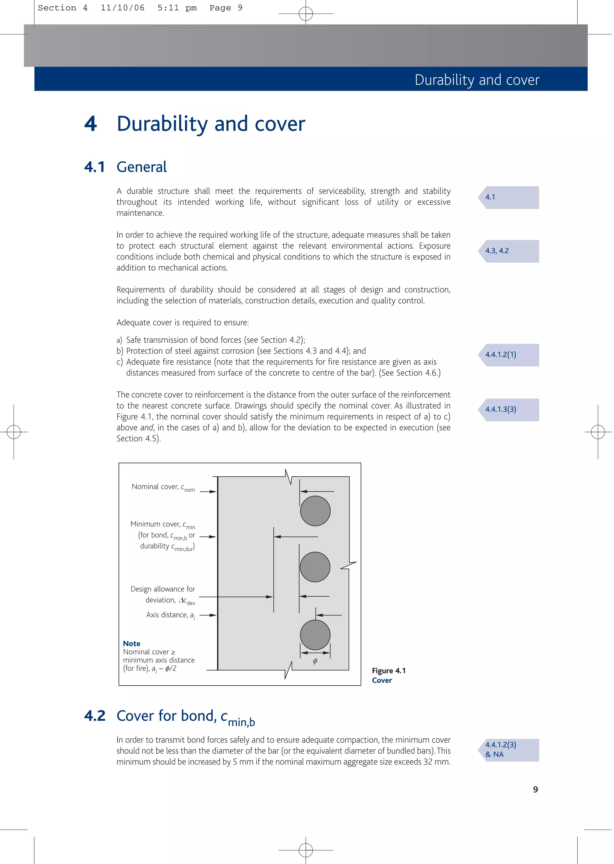
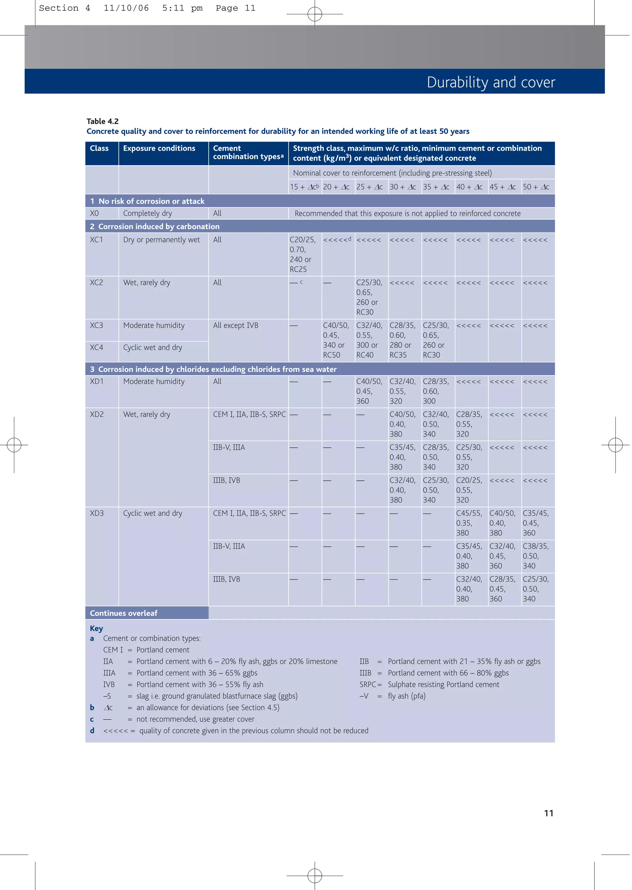
4.3 Cover for durability, cmin,dur
Environmental conditions are classified according toTable 4.1, which is based on BS EN 206-1[12].
Concrete composition and minimum covers required for durability in different environmental
conditions are set out in Tables 4.2 and 4.3, derived from BS 8500[13]. These tables give
recommendations for normal weight concrete using maximum aggregate size of 20 mm for
selected exposure classes and cover to reinforcement. For each applicable exposure class, the
minimum covers and required strength class or equivalent designated concrete should be
determined from Tables 4.2 or 4.3 as appropriate and the worst case taken for use.
10
5 Freeze/thaw attack
6 Chemical attack
Table 4.1
Section 4 11/10/06 5:11 pm Page 10](https://image.slidesharecdn.com/conciseeurocode2-220718034157-f2f98aab/75/Concise_Eurocode_2-pdf-20-2048.jpg)
![Exposure conditions Cement
combination typesa
Strength class, maximum w/c ratio, minimum cement or combination
content (kg/m3) or equivalent designated concrete
Nominal cover to reinforcement (including pre-stressing steel)
In accordance with BS 8500[13], special attention should be given to the concrete composition
and aggregates, when considering freeze/thaw attack, chemical attack or abrasion resistance.
Exposure conditions, XF, only affect concrete quality and do not directly affect the corrosion of
reinforcement. However:
■ XF1 is likely to coexist with XC3 and XC4; the requirements for XC3 and XC4 satisfy those
for XF1 but, in such cases, a minimum of strength class C28/35 should be used.
■ XF2 is likely to coexist with XD3; the requirements for XD3 satisfy those for XF2.
■ XF3 is likely to coexist with XC3 and XC4; the requirements for XC3 and XC4 satisfy those
for XF3 providing air entrainment and freeze/thaw resisting aggregates are used or
alternatively a minimum strength class C40/50 with freeze/thaw resisting aggregates is
used.
■ XF4 is likely to coexist with XD3. Using cement combination types 1, 11A, 11B-S and SRPC,
the requirements for XD3 satisfy those for XF4 provided freeze/thaw resisting aggregates
and a minimum strength class of C40/50 are used. Alternatively, using cement/
combination type 111B, the requirements for XD3 satisfy those of XF4 provided air
entrainment and minimum strength class of C28/35 are used.
12
Table 4.2
Continued
Class
15 + Dc
XS1
XS2
XS3
15 + Dc
Airborne salts but no
direct contact
Wet, rarely dry
Tidal, splash and spray
zones
15 + Dcb
— c
—
—
—
—
—
—
—
—
20 + Dc
—
—
—
—
—
—
—
—
—
25 + Dc
—
—
—
—
—
—
—
—
—
30 + Dc
C50/60,
0.35,
380
C45/55,
0.35,
380
C35/45,
0.40,
380
C40/50,
0.40,
380
C35/45,
0.40,
380
C32/40,
0.40,
380
—
—
—
35 + Dc
C40/50,
0.45,
360
C35/45,
0.45,
360
C28/35,
0.50,
340
C32/40,
0.50,
340
C28/35,
0.50,
340
C25/30,
0.50,
340
—
—
—
40 + Dc
C35/45,
0.50,
340
C32/40,
0.50,
340
C25/30,
0.55,
320
C28/35,
0.55,
320
C25/30,
0.55,
320
C20/25,
0.55,
320
—
C35/45,
0.40,
380
C32/40,
0.40,
380
45 + Dc
<<<<<d
<<<<<
<<<<<
<<<<<
<<<<<
<<<<<
C45/55,
0.35,
380
C32/40,
0.45,
360
C28/35,
0.45,
360
50 + Dc
<<<<<
<<<<<
<<<<<
<<<<<
<<<<<
<<<<<
C40/50,
040,
380
C28/35,
0.50,
340
C25/30,
0.50,
340
4 Corrosion induced by chlorides from sea water
CEM 1, 11A, 11B-S, SRPC
11B-V, 111A
111B, 1VB
CEM 1, 11A, 11B-S, SRPC
11B-V, 111A
111B, 1VB
CEM 1, 11A, 11B-S, SRPC
11B-V, 11A
11B, 1VB
BS 8500
Section 4 11/10/06 5:11 pm Page 12](https://image.slidesharecdn.com/conciseeurocode2-220718034157-f2f98aab/75/Concise_Eurocode_2-pdf-22-2048.jpg)
![Exposure conditions Cement
combination typesa
Strength class, maximum w/c ratio, minimum cement or combination
content (kg/m3) or equivalent designated concrete
Nominal cover to reinforcement (including pre-stressing steel)
Class
Durability and cover
13
4.4 Chemical attack
For foundations, an aggressive chemical environment for concrete (ACEC) class should be
assessed for the site. BS 8500-1 refers to BRE Special Digest 1[17] which identifies ACEC
classes rather than XA classes.
Knowing the ACEC class for sections with a thickness of at least 140 mm and an intended
working life of either 50 or 100 years, a design chemical (DC) class can be obtained and an
appropriate designated concrete (e.g. FND designation) selected.
For designed concrete, the concrete producer should be advised of the DC class.
Alternatively, a designated FND concrete, which has a minimum strength class of C28/35,
can be specified. Additional protective measures may be necessary, see BS 8500[13].
4.5 ∆cdev and other allowances
The minimum covers for bond in Section 4.2 and for durability in Tables 4.2 and 4.3 should be
increased by an allowance in design, Dcdev to allow for likely deviations during execution as
follows.:
■ 10 mm generally.
■ Between 5 and 10 mm, where a QA system operates and concrete cover is measured.
■ Between 0 and 10 mm, where non-conforming members are rejected on the basis of
accurate measurement of cover (e.g. precast elements).
Table 4.3
Concrete quality and cover to reinforcement for durability for an intended working life of 100 years
15 + Dc
X0
XC1
XC2
XC3
XC4
15 + Dc
Completely dry
Dry or permanently wet
Wet, rarely dry
Moderate humidity
Cyclic wet and dry
15 + Dc
All
All
All
All
All except 1VB
15 + Dcb
C20/25,
0.70,
240 or
RC25
— c
—
20 + Dc
<<<<<d
—
—
25 + Dc
<<<<<
C25/30,
0.65,
260 or
RC30
—
30 + Dc
<<<<<
<<<<<
C40/50,
0.45,
340 or
RC50
35 + Dc
<<<<<
<<<<<
C35/45,
0.50,
320 or
RC45
40 + Dc
<<<<<
<<<<<
C32/40,
0.55,
300 or
RC40
45 + Dc
<<<<<
<<<<<
C28/35,
0.60,
280 or
RC35
50 + Dc
<<<<<
<<<<<
<<<<<
Recommended that this exposure is not applied to reinforced concrete
Key
a Cement or combination types:
CEM 1 = Portland cement
11A = Portland cement with 6 – 20% fly ash, ggbs or 20% limestone 11B = Portland cement with 21 – 35% fly ash or ggbs
111A = Portland cement with 36 – 65% ggbs 111B = Portland cement with 66 – 80% ggbs
1VB = Portland cement with 36 – 55% fly ash SRPC = Sulphate resisting Portland cement
–S = slag i.e. ground granulated blastfurnace slag (ggbs) –V = fly ash (pfa)
b Dc = an allowance for deviations (see Section 4.5)
c — = not recommended, use greater cover
d <<<<< = quality of concrete given in the previous column should not be reduced
1 No risk of corrosion or attack
2 Corrosion induced by carbonation
4.4.1.3(1)
& NA
Section 4 11/10/06 5:11 pm Page 13](https://image.slidesharecdn.com/conciseeurocode2-220718034157-f2f98aab/75/Concise_Eurocode_2-pdf-23-2048.jpg)
![Dcdev is recognised in BS 8500[13] as Dc and in prEN 13670[10] as Dc(minus). In terms of execution
tolerances Dc(minus) andDc(plus) are subject to prEN 13670 and/or the project’s specification.
The minimum cover for concrete cast on prepared ground (including blinding) is 40 mm and
that for concrete cast directly against soil is 65 mm.
Additional cover should be considered for textured or profiled surfaces.The minimum covers in
Tables 4.2 and 4.3 should, in these situations, be increased by at least 5 mm.
For prestressing steel, subject to XD exposure conditions, an additional allowance, Dc,durg, of
10 mm should be allowed for intended working lives of 50 and 100 years.
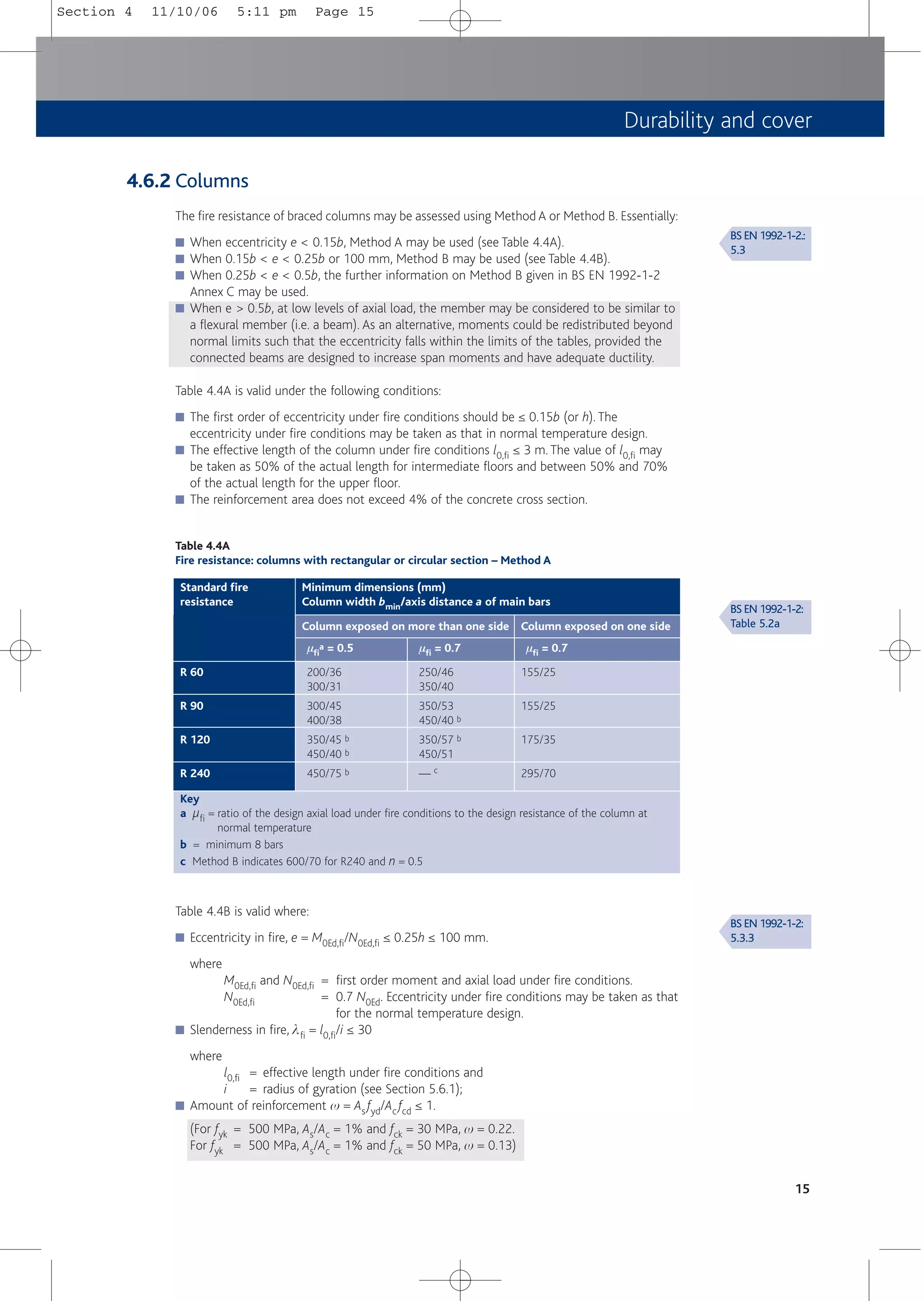
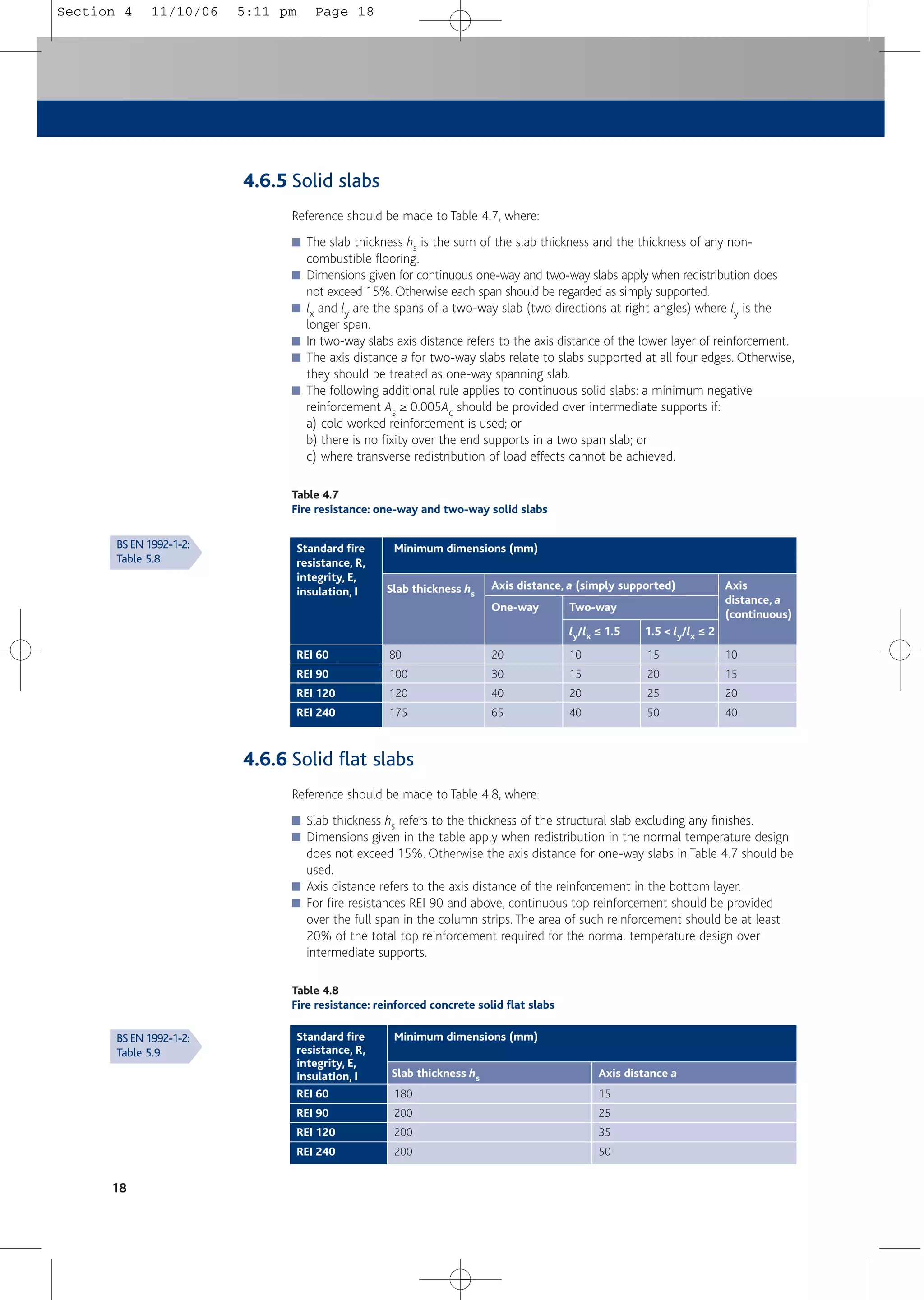
4.6 Cover for fire resistance
4.6.1 General
Minimum sizes of members and axis distance to reinforcement for achieving fire resistance are
defined in Figures 4.2 and 4.3 and given in Tables 4.4 to 4.10.These are based on the tabulated
data in BS EN 1992-1-2[2] and its UK National Annex[2a] and indicate whether the resistance
relates to fire resistance for actions, R, integrity, E, and/or insulation, I. Fire engineering methods
are available; these are introduced in Section 4.6.10.
Axis distances for prestressing bars are generally 10 mm greater and for prestressing wires and
strands 15 mm greater.
14
Figure 4.2
Section through a
structural member
showing nominal axis
distance a, and axis
distance to side of
section asd
asd
a
h ≥ b
b
Figure 4.3
Definition of dimensions for different types of beam section
hs
am
bw
b b
b
a) Constant width b) Variable width c) I-Section
Note
am = average axis distance, hs = depth of slab
4.4.1.3(4)
& NA
4.4.1.2(11)
4.4.1.2(6)
& NA
PD 6687
BS EN 1992-1-2:
Sections 4.2,
4.3 & 5
BS EN 1992-1-2:
Fig. 5.2
BS EN 1992-1-2:
Fig. 5.4
Section 4 11/10/06 5:11 pm Page 14](https://image.slidesharecdn.com/conciseeurocode2-220718034157-f2f98aab/75/Concise_Eurocode_2-pdf-24-2048.jpg)
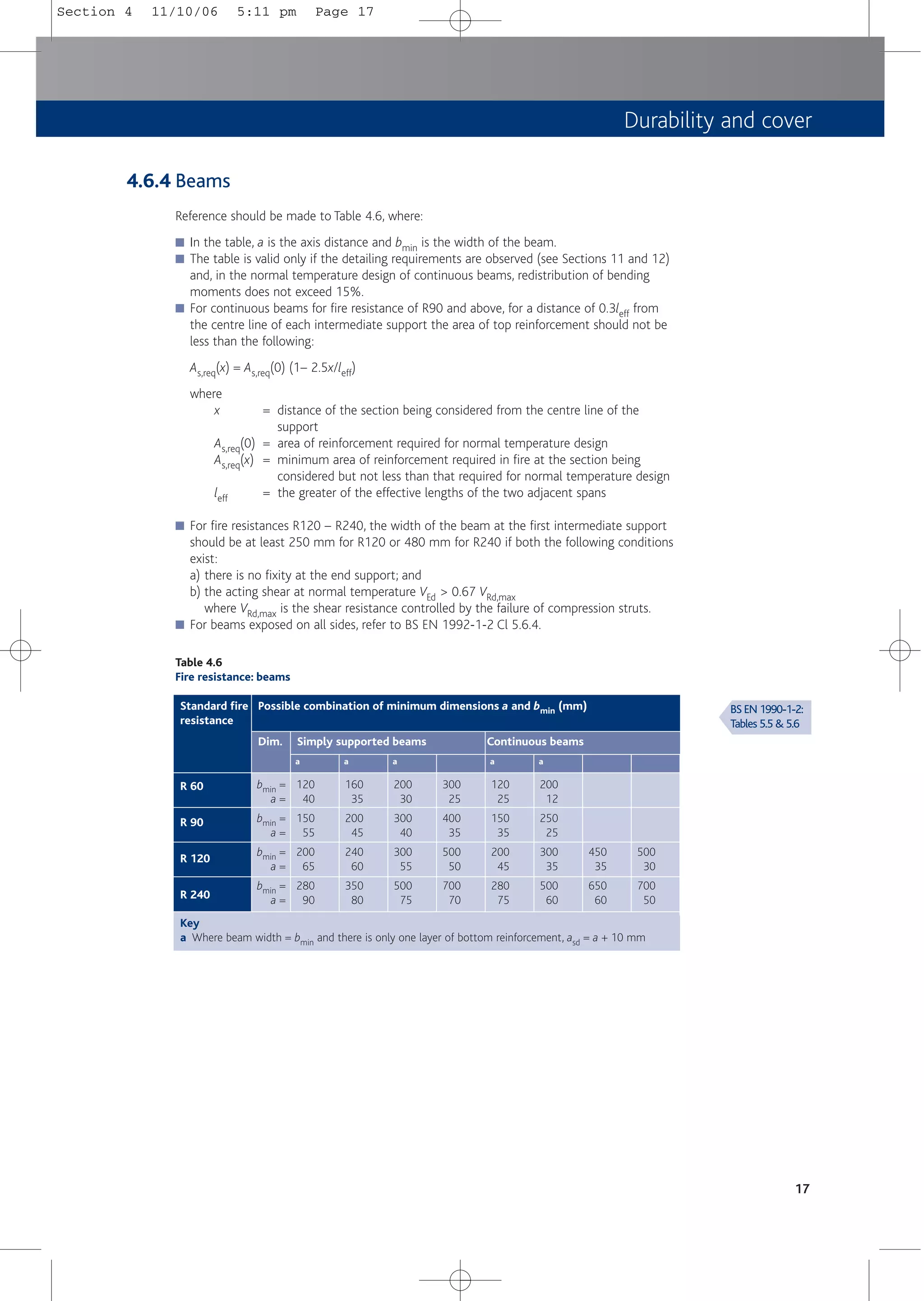
![4.6.9 Covers for fire resistance when using >15% redistribution
Tables 4.6, 4.7 and 4.8 are restricted in their use to where, in the normal temperature design,
redistribution of bending moments does not exceed 15%.
For beams (and continuous ribbed slabs), where redistribution exceeds 15%, the beam should
be treated as simply supported or the rotational capacity at the supports should be checked,
for example, by using BS EN 1992-1-2 Annex E.
For continuous solid slabs and continuous solid flat slabs, provided:
a) the all-spans-loaded case is used (see Section 5.4.2);
b) redistribution is restricted to 20%;
c) Qk > 0.5Gk; and
d) bar diameter, f ≥ 12 mm;
then Tables 4.7 and 4.8 may be used for fire ratings up to R120. However, if nominal cover,
cnom < 25 mm, bar diameter, f, should be ≥ 16 mm and for f = 16 mm only, As,prov/As,req
should be ≥ 1.11[19].
4.6.10 Fire engineering
BS EN 1992-1-2 allows for simplified and advanced calculation methods to determine the
capacities of sections in fire. Fire design is based on verifying that the effects of actions in fire
are not greater than the resistance in fire after time, t, i.e. that Ed,fi ≤ Rd,fi(t). In that assessment:
■ Actions (loads) are taken from BS EN 1991-1-2[6]
■ Member analysis is based on the equation Ed,fi = hfiEd
where
Ed = design value of the corresponding force or moment for normal temperature
design
hfi = reduction factor for the design load level for the fire incident
Simplified calculation methods include the 500ºC isotherm method, the zone method and
checking buckling effects in columns. These methods and advanced calculation methods, used
for very complex structures, are beyond the scope of this publication.
20
BS EN 1992-1-2:
4.2, 4.3
Section 4 11/10/06 5:11 pm Page 20](https://image.slidesharecdn.com/conciseeurocode2-220718034157-f2f98aab/75/Concise_Eurocode_2-pdf-30-2048.jpg)
![Structural analysis
25
5.4.3 Load factors
For the numerical values of the factors to be used in a load case see Section 2.3.4.
N.B. gG is constant throughout.
5.5 Geometrical imperfections
5.5.1 General
For ULS, the unfavourable effects of possible deviations in the geometry of the structure and
the position of actions shall be taken into account when verifying stability.These are in addition
to other destabilising forces applied to the structure (e.g. wind actions).
5.5.2 Imperfections and global analysis of structures
For the global analysis of structures imperfections may be represented by an inclination qi of
the whole structure.
qi = (1/200)aham
where
ah = 0.67 ≤ 2/l0.5 ≤ 1.0
am = [0.5 (1 + 1/m)]0.5
l = height of the structure in metres
m = number of vertical members contributing to the effect
The effect of the inclination may be represented by transverse forces at each level to be
included in the analysis with other actions. The horizontal action at any level is applied in the
position that gives maximum moment.
Hi = qiNk
where
Hi = action applied at that level
N = axial load
k = 1.0 for unbraced members
= 2.0 for braced members
= (Nb – Na)/N for bracing systems (see Figure 5.5a)
= (Nb + Na)/2N for floor diaphragms (see Figure 5.5b)
= Na/N for roof diaphragms
where
Nb and Na are longitudinal forces contributing to Hi
5.5.3 Other allowances in analysis
Allowances for imperfections are also made in:
■ Partial factors used in cross section design.
■ Compression members (see Section 5.6.2).
5.2
5.2(5)
5.2(7)
5.2(8)
Section 5 11/10/06 5:12 pm Page 25](https://image.slidesharecdn.com/conciseeurocode2-220718034157-f2f98aab/75/Concise_Eurocode_2-pdf-35-2048.jpg)
![26
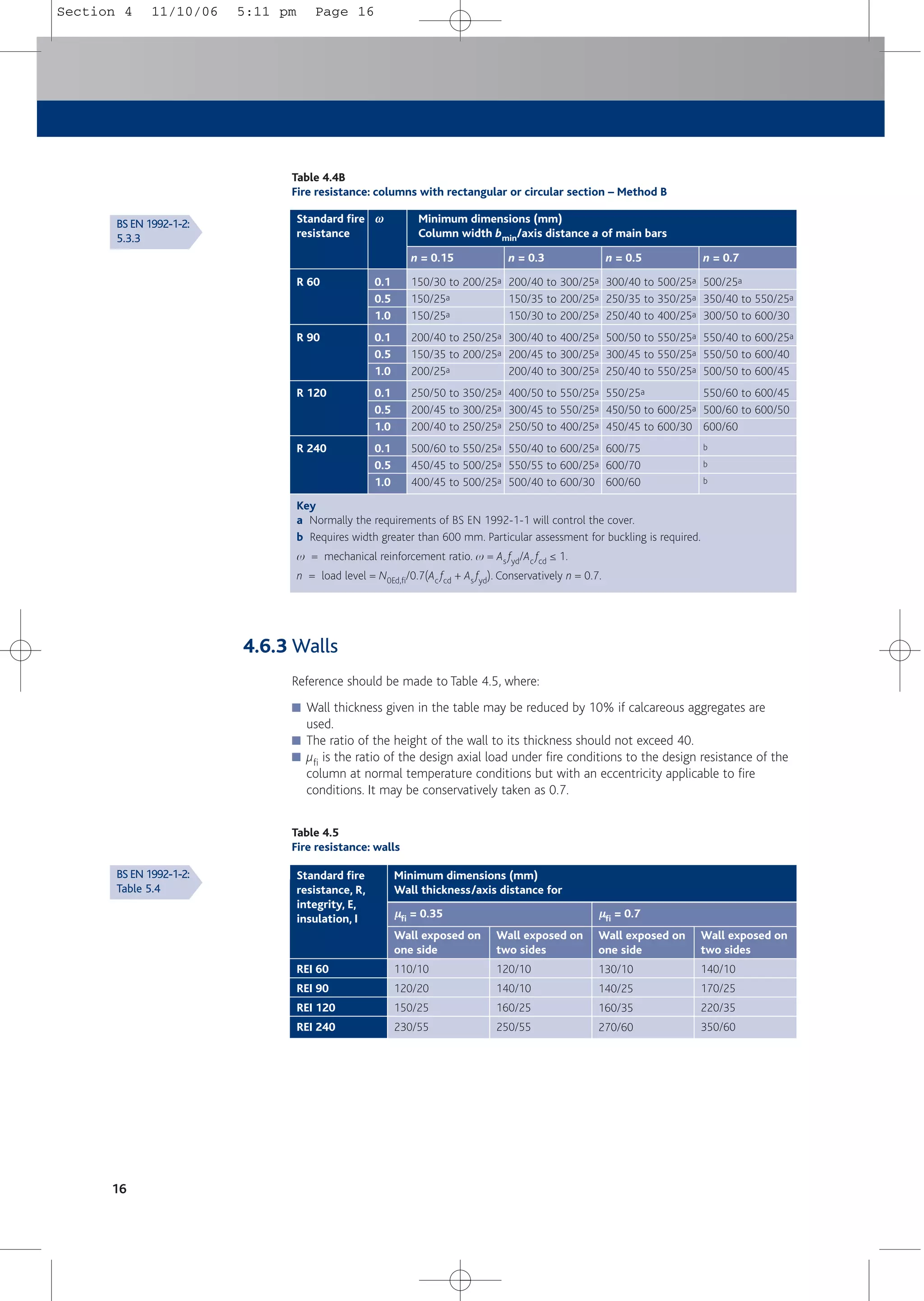
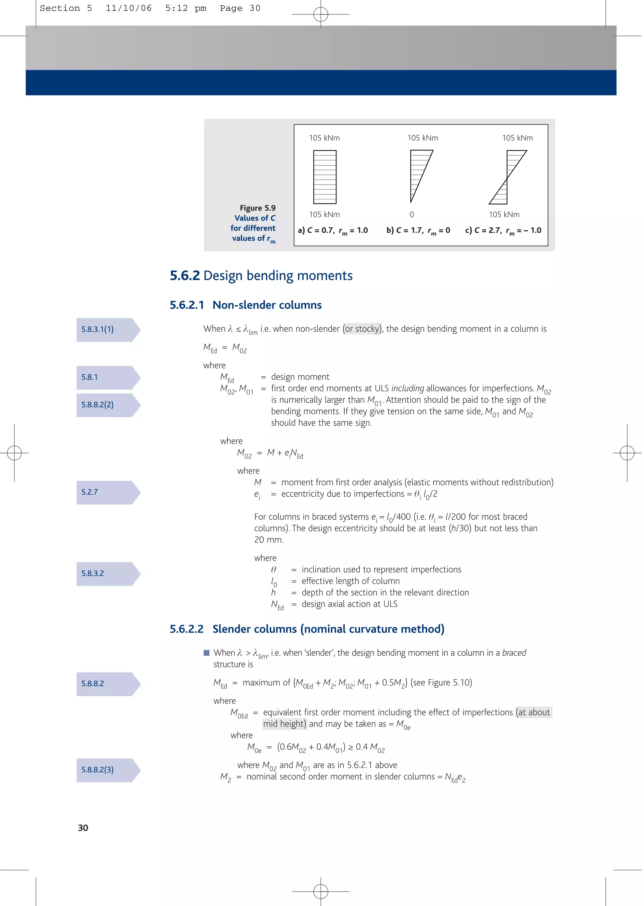
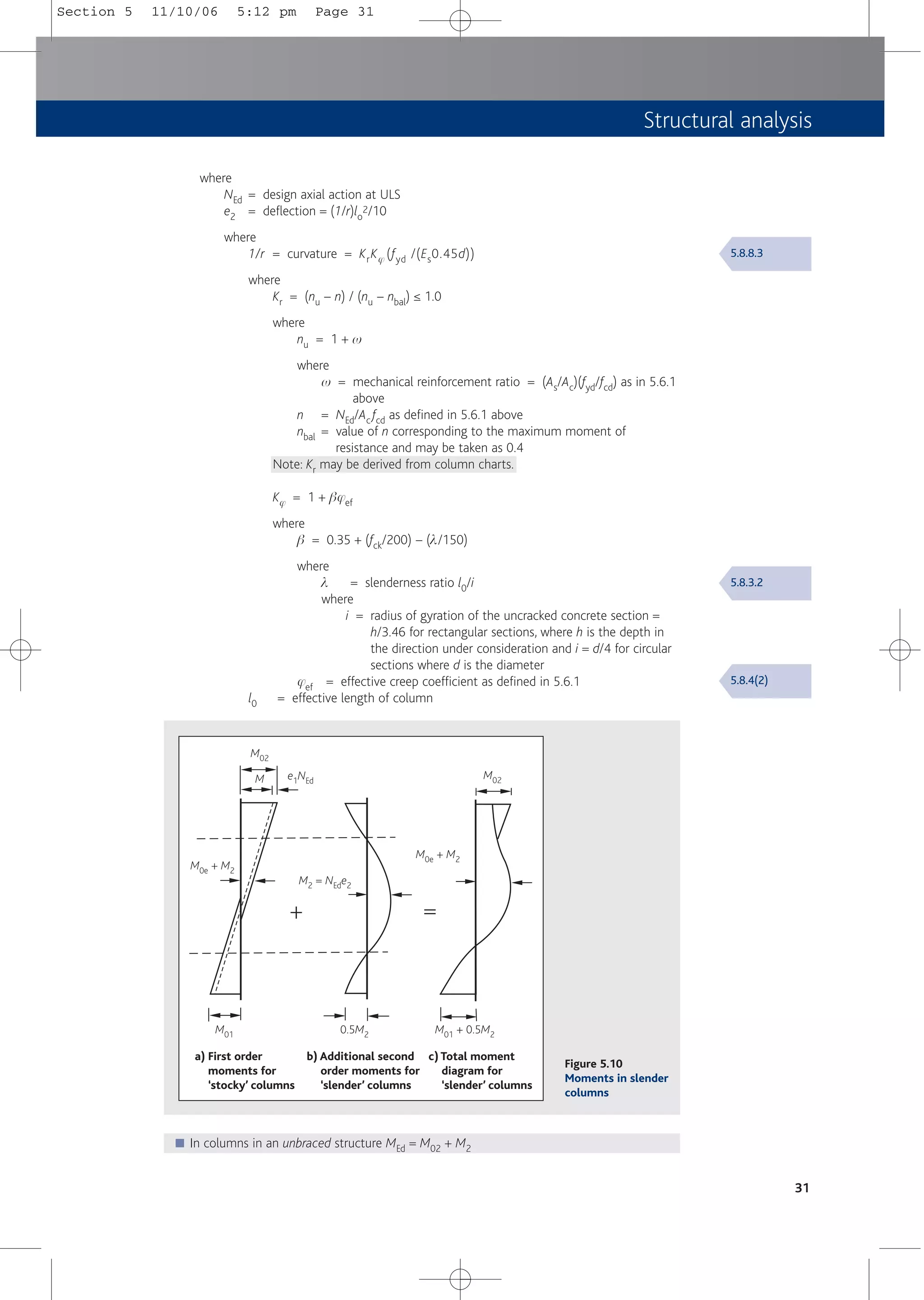
5.6 Design moments in columns
5.6.1 Definitions
5.6.1.1 Bracing members
Bracing members are members that contribute to the overall stability of the structure, whereas
braced members do not contribute to the overall stability of the structure.
5.6.1.2 Effective length l0
For braced members:
l0 = 0.5l[1 + k1/(0.45 + k1)]0.5 [1 + k2/(0.45 + k2)]0.5
For unbraced members l0 is the larger of either:
l0 = l[1 + 10k1k2/(k1 + k2)]0.5
or
l0 = l[1 + k1/(1.0 + k1)] [1 + k2/(1.0 + k2)]
where
l = clear height of the column between the end restraints
k1, k2 = relative flexibilities of rotational restraints at ends 1 and 2 respectively
In regular structures, in which the stiffness of adjacent columns does not vary significantly (say,
difference not exceeding 15% of the higher stiffness), it is recommended that the relative
flexibility of each end of the column is calculated ignoring the contributions of the adjacent
columns.The contribution of each attached beam should be modelled as 2E1/lbeam to allow for
the effect of cracking.
Examples of different buckling modes and corresponding effective length factors for isolated
members are shown in Figure 5.6.
A simplified method for determining effective length factors is given in How to design concrete
structures using Eurocode 2: Columns[20]. Conservative effective length factors for braced
columns can be obtained from Table 5.1, where l0 = l x factor.
5.8.1
5.8.3.2(3)
PD 6687[7]
5.8.3.2(2)
Figure 5.5
Examples of the effect
of geometric
imperfections
Hi
Na
Nb
qi
Hi
Na
Nb
qi /2
qi /2
l
a) Bracing system b) Floor diaphragm
Fig. 5.1
Section 5 11/10/06 5:12 pm Page 26](https://image.slidesharecdn.com/conciseeurocode2-220718034157-f2f98aab/75/Concise_Eurocode_2-pdf-36-2048.jpg)
![Table 5.1
Effective length l0: conservative factors for braced columns
Structural analysis
27
q
q
q
Figure 5.6
Examples of different buckling modes and corresponding effective lengths for isolated members
l
M
a) l0 = l b) l0 = 2l c) l0 = 0.7l d) l0 = l/2 e) l0 = l f) l/2 < l0 < l g) l0 > 2l
Key
Condition 1 Column connected monolithically to beams on each side that are at least as deep as the
overall depth of the column in the plane considered
Where the column is connected to a foundation this should be designed to carry moment
in order to satisfy this condition
Condition 2 Column connected monolithically to beams on each side that are shallower than the
overall depth of the column in the plane considered by generally not less than half the
column depth
Condition 3 Column connected to members that do not provide more than nominal restraint to
rotation
Note
Table taken from Manual for the design of concrete building structures to Eurocode 2[21]. The values are
those used in BS 8110: Part 1: 1997[14] for braced columns. These values are close to those values that
would be derived if the contribution from adjacent columns were ignored.
5.8.3.2(1)
End condition
at top
End condition at bottom
Fig. 5.7
5.6.1.3 Slenderness ratio, l
Slenderness ratio l = l0/i
where
i = the radius of gyration of the uncracked concrete section
Ignoring reinforcement:
l = 3.46 l0/h for rectangular sections
= 4.0 l0/d for circular sections
where
h = the depth in the direction under consideration
d = the diameter
1
2
3
1
0.75
0.80
0.90
2
0.80
0.85
0.95
3
0.90
0.95
1.00
Section 5 11/10/06 5:12 pm Page 27](https://image.slidesharecdn.com/conciseeurocode2-220718034157-f2f98aab/75/Concise_Eurocode_2-pdf-37-2048.jpg)
![6.2 Derived formulae
The following formulae may be derived by using Figures 6.1, 6.2 and 6.3.
6.2.1 Bending
Assuming K and K' have been determined:
where
K = M/bd2fck
K' = 0.598d – 0.18d2 – 0.21 (see Table 6.1)
where
d ≤ 1.0 = redistribution ratio (see Table 6.1)
■ If K ≤ K'
then
As1 = M/fydz
where
As1 = area of tensile reinforcement (in layer 1)
fyd = fyk/gs = 500/1.15 = 434.8 MPa
z = d[0.5 + 0.5(1 - 3.53K)0.5] ≤ 0.95d
■ If K > K'
then
As2 = (M – M')/fsc(d – d2)
where
As2 = area of compression steel (in layer 2)
M' = K'bd2fck
fsc = 700(xu – d2)/xu ≤ fyd
where
d2 = effective depth to compression steel
xu = (d – 0.4)d
and
As1 = M'/fydz + As2 fsc/fyd
For As,min see Section 12, Table 12.1.
38
Table 6.1
Values for K’
Redistribution ratio, δ
δ
Percent redistribution K’
1.00
0.95
0.90
0.85
0.80
0.75
0.70
0%
5%
10%
15%
20%
25%
30%
0.208
0.195
0.182
0.168
0.153
0.137
0.120
Section 6 11/10/06 5:12 pm Page 38](https://image.slidesharecdn.com/conciseeurocode2-220718034157-f2f98aab/75/Concise_Eurocode_2-pdf-48-2048.jpg)
![Bending and axial force
39
a) Strain diagram b) Stress diagram
n. axis
fcd = acchfck/gc
d2
dc x
h
d2
ssc
sst
ecu2
esc
ey
As1
As2
Figure 6.4
Section in axial
compression and
bending
6.2.2 Axial load and bending
Assuming a rectangular section, symmetrical arrangement of reinforcement and ignoring side
bars:
■ For axial load
AsN/2 = (NEd – acchfckbdc /gc)/[(ssc – sst)
where
AsN = total area of reinforcement required to resist axial load using this method
= As1 + As2 and As1 = As2
where
As1(As2) = area of reinforcement in layer 1 (layer 2), see Figure 6.3
NEd = design applied axial force
acc = 0.85
h = 1 for ≤ C50/60
b = breadth of section
dc = effective depth of concrete in compression = lx ≤ h (see Figure 6.4)
where
l = 0.8 for ≤ C50/60
x = depth to neutral axis
h = height of section
ssc (sst) = stress in compression (and tension) reinforcement ≤ fyk/gs
■ For moment
AsM/2 = [MEd – acchfckbdc(h/2 – dc/2)/gc]/[(h/2 – d2)(ssc + sst)]
where
AsM = total area of reinforcement required to resist moment using this method.
= As1 + As2 and As1 = As2
■ Solution
Solve by iterating x such that AsN = AsM, or refer to charts or spreadsheets etc.
3.1.6(1)
& NA
Fig. 6.1
Section 6 11/10/06 5:12 pm Page 39](https://image.slidesharecdn.com/conciseeurocode2-220718034157-f2f98aab/75/Concise_Eurocode_2-pdf-49-2048.jpg)
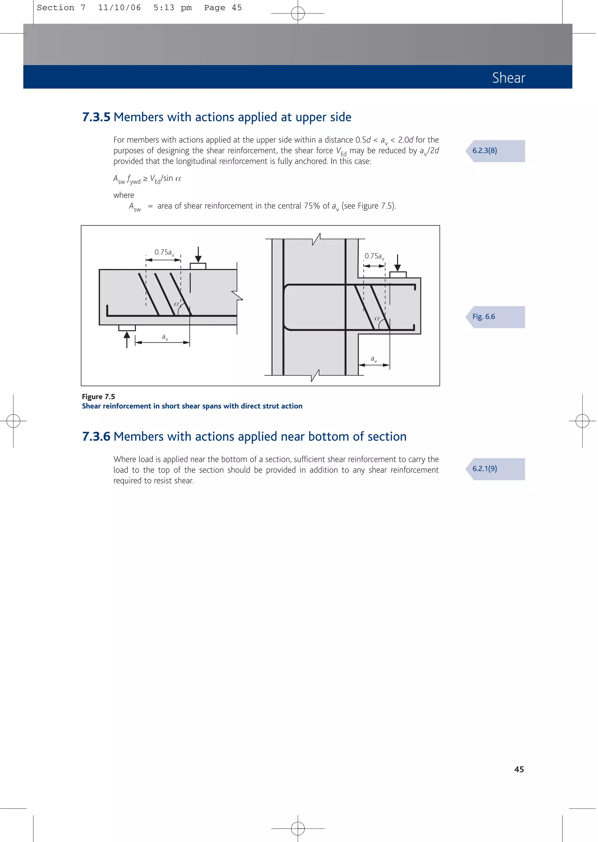
![Shear
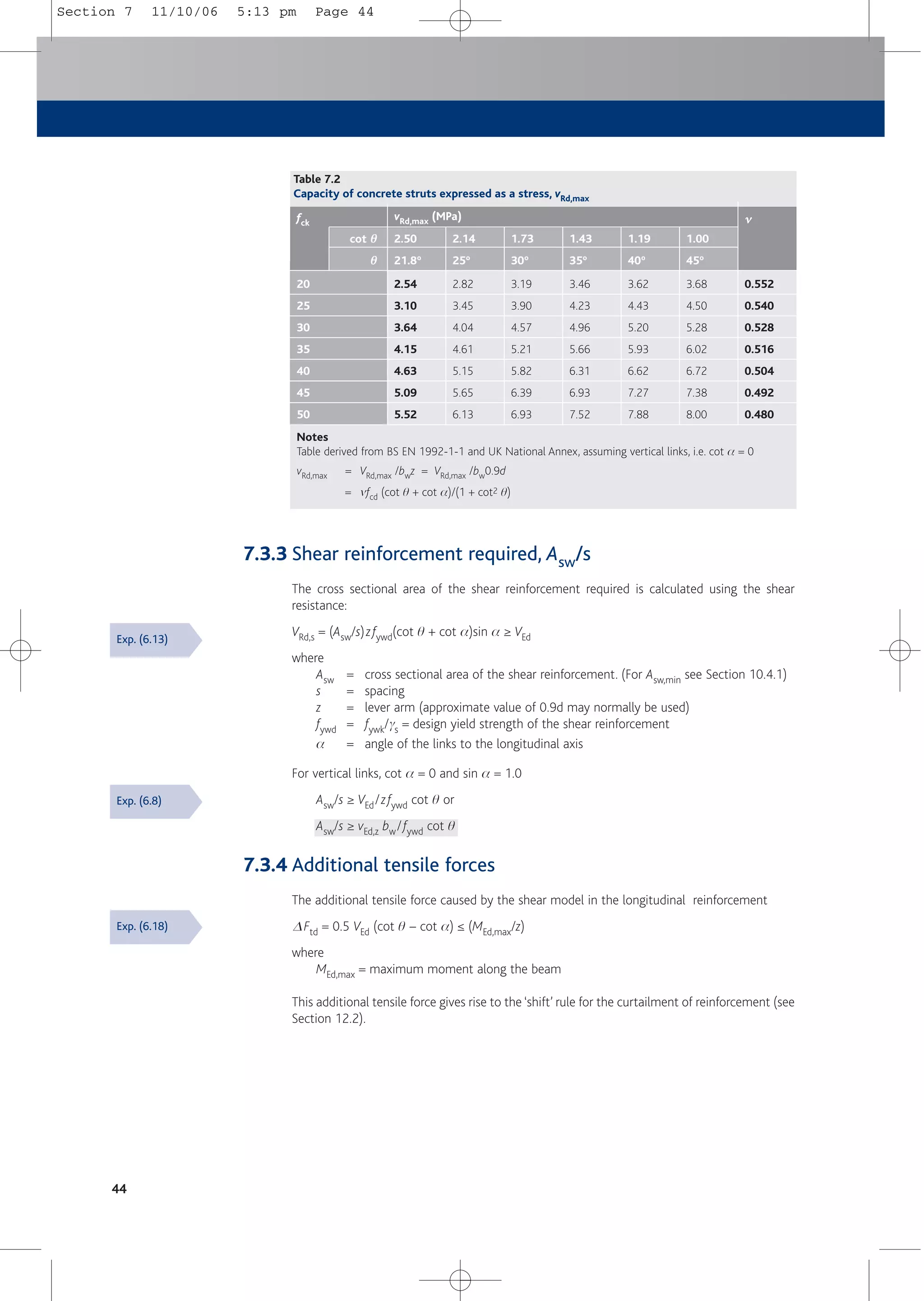
7.3.2 Shear capacity check
The capacity of the concrete section to act as a strut VRd,max should be checked to ensure that
it equals or exceeds the design shear force, VEd i.e. ensure that:
VRd,max = bw z m fcd /(cot q + tan q) ≥ VEd with vertical links
= bw z m fcd(cot q + cot a)/(1 + cot2 q) ≥ VEd with inclined links
where
z = lever arm: an approximate value of 0.9d may normally be used
m = 0.6 [1 – (fck/250)] = strength reduction factor for concrete cracked in shear
fcd = acw fck/gc with acw = 1.0
q = angle of inclination of the strut, such that cot q lies between 1.0 and 2.5.
The value of cot q should be obtained by substituting VEd for VRd,max
a = angle of inclination of the links to the longitudinal axis.
For vertical links cot a = 0.
In most practical cases, where vertical links are used, it will be sufficient to check stresses
(rather than capacities) using Table 7.2 such that:
vEd,z ≤ vRd, max
where
vEd,z = VEd/bwz = VEd/bw0.9d = shear stress in sections with shear reinforcement
vRd,max = VRd,max /bwz = VRd,max/bw0.9d
If vEd,z ≤ the value of vRd,max for cot q = 2.5, then q = 21.8º and cot q = 2.5
If vEd,z > the value of vRd,max for cot q = 1.0, then the section should be resized
If vEd,z is between the values for cot q = 2.5 and cot q = 1.0, then q and cot q should be
calculated from the equation for VRd,max, but substituting VEd for VRd,max
Values of vRd,max may be interpolated from Table 7.2.
43
Exp. (6.9)
Exp. (6.14)
& NA
6.2.3(3)
& NA
Concrete strut in compression
Longitudinal reinforcement in tension
Vertical shear reinforcement
q
Figure 7.4
Variable strut angle, θ
θ
Section 7 11/10/06 5:13 pm Page 43](https://image.slidesharecdn.com/conciseeurocode2-220718034157-f2f98aab/75/Concise_Eurocode_2-pdf-53-2048.jpg)
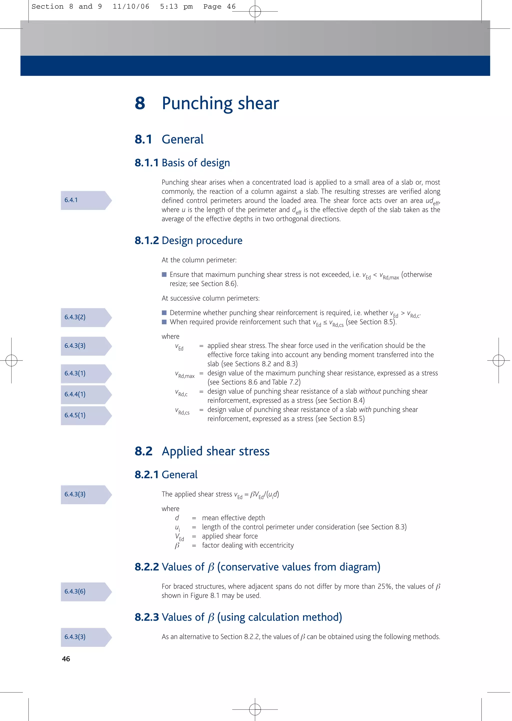
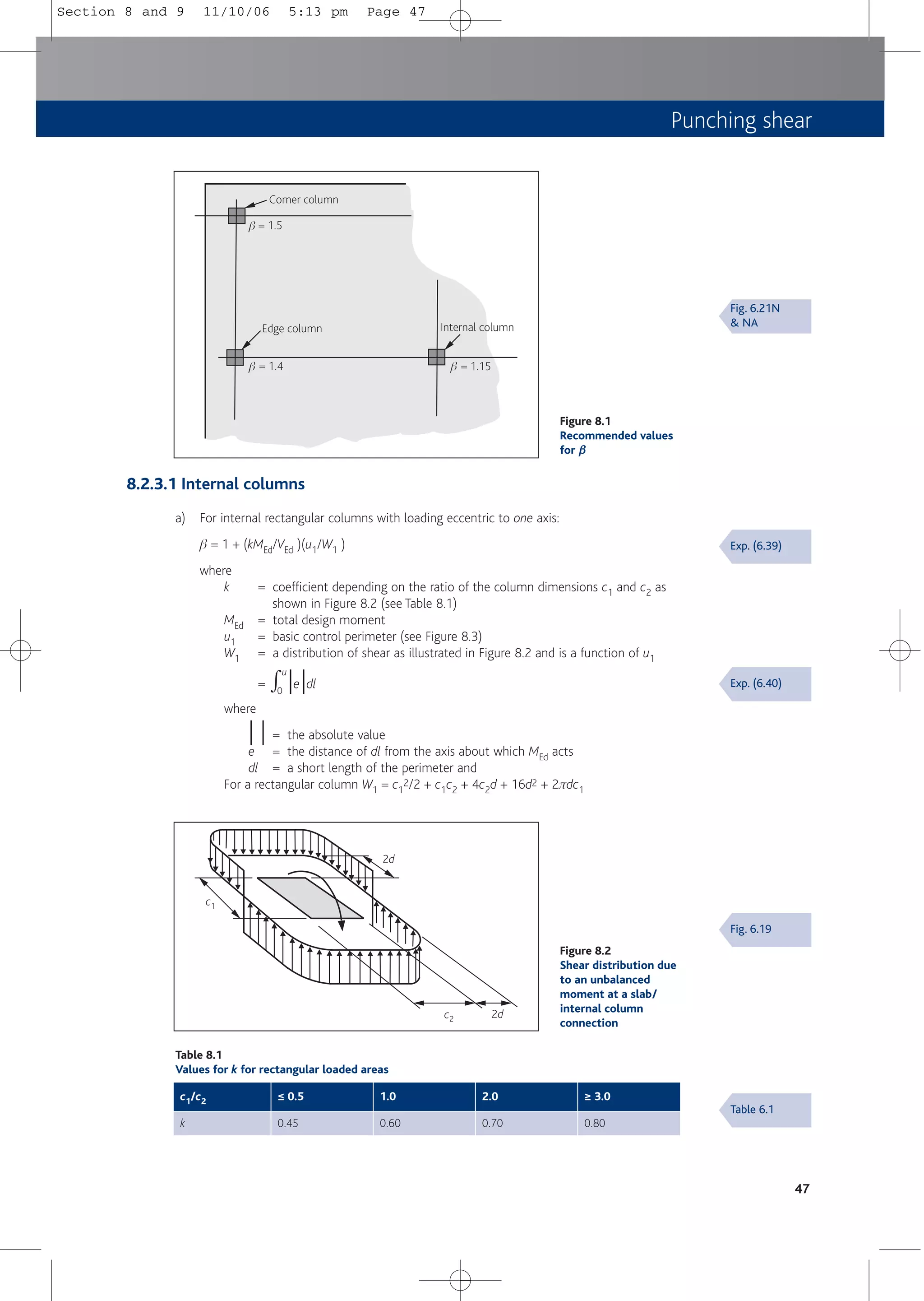
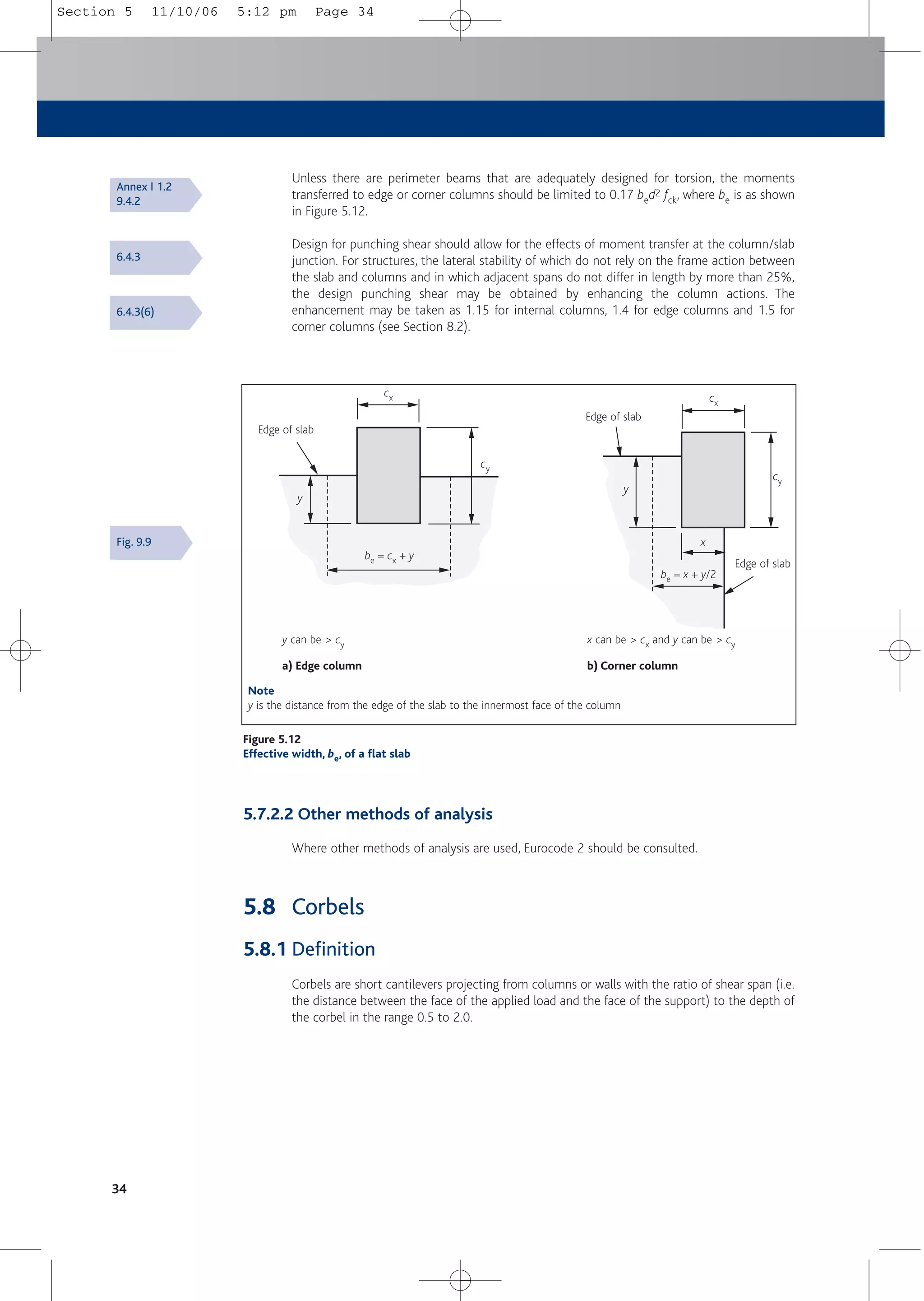
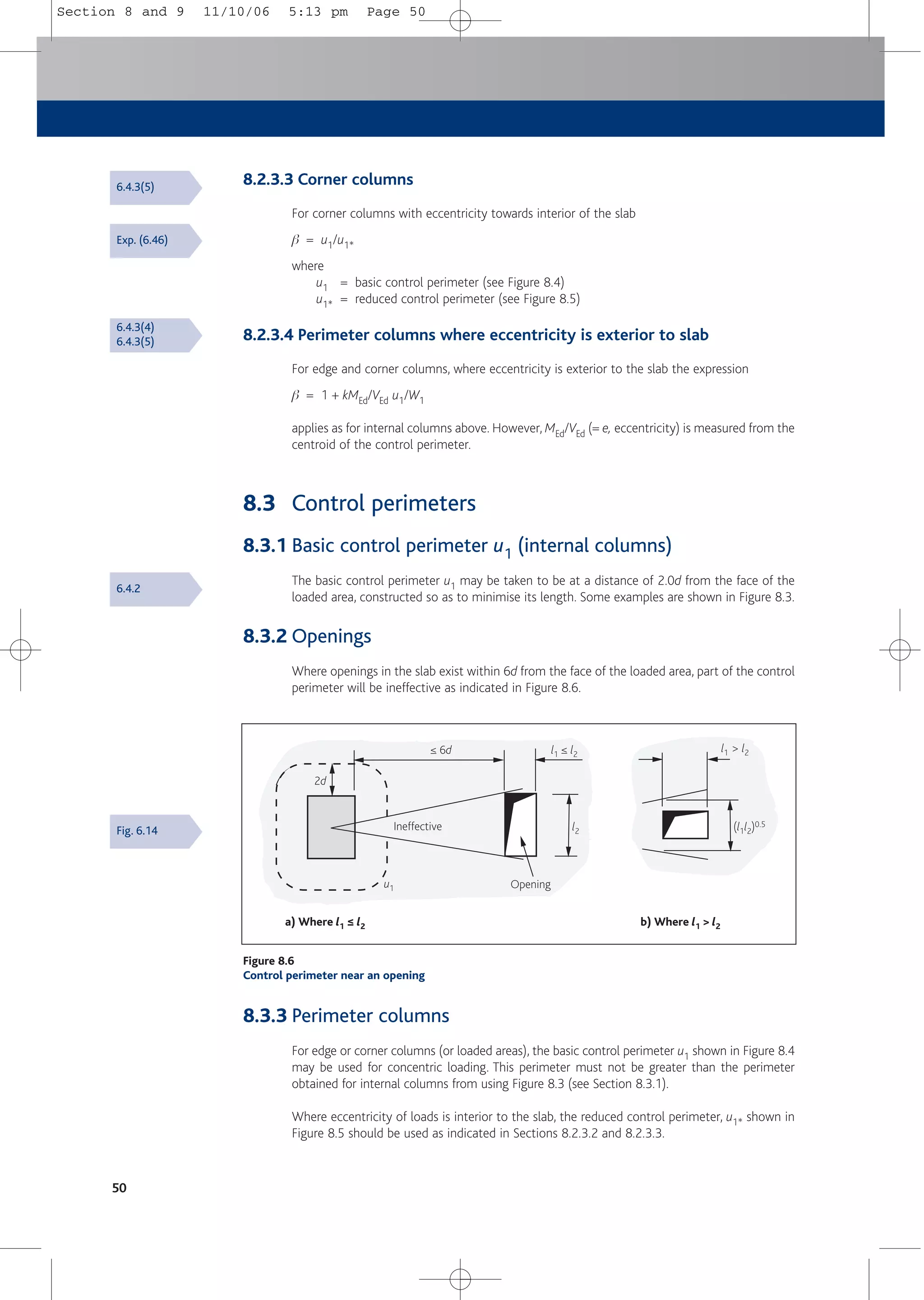
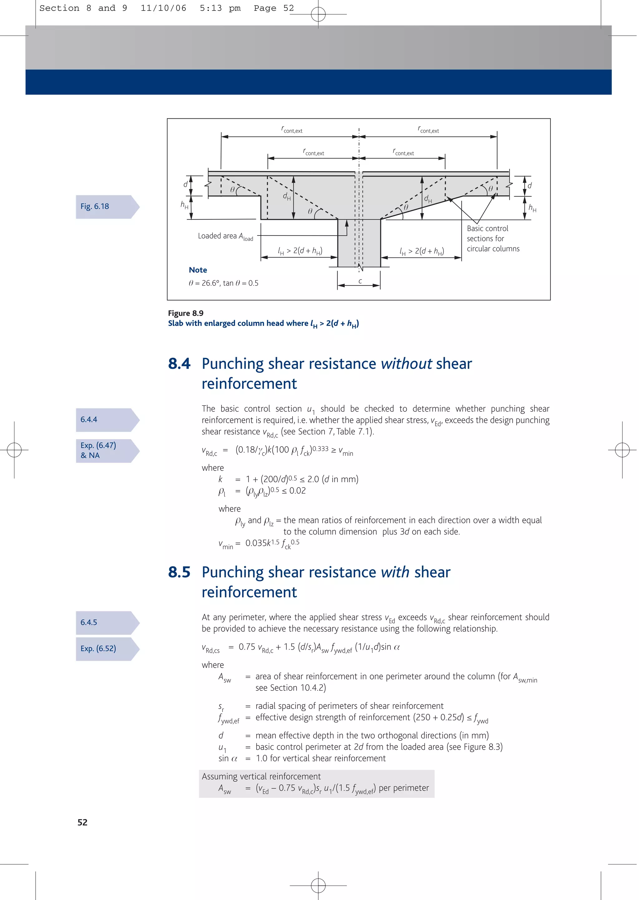
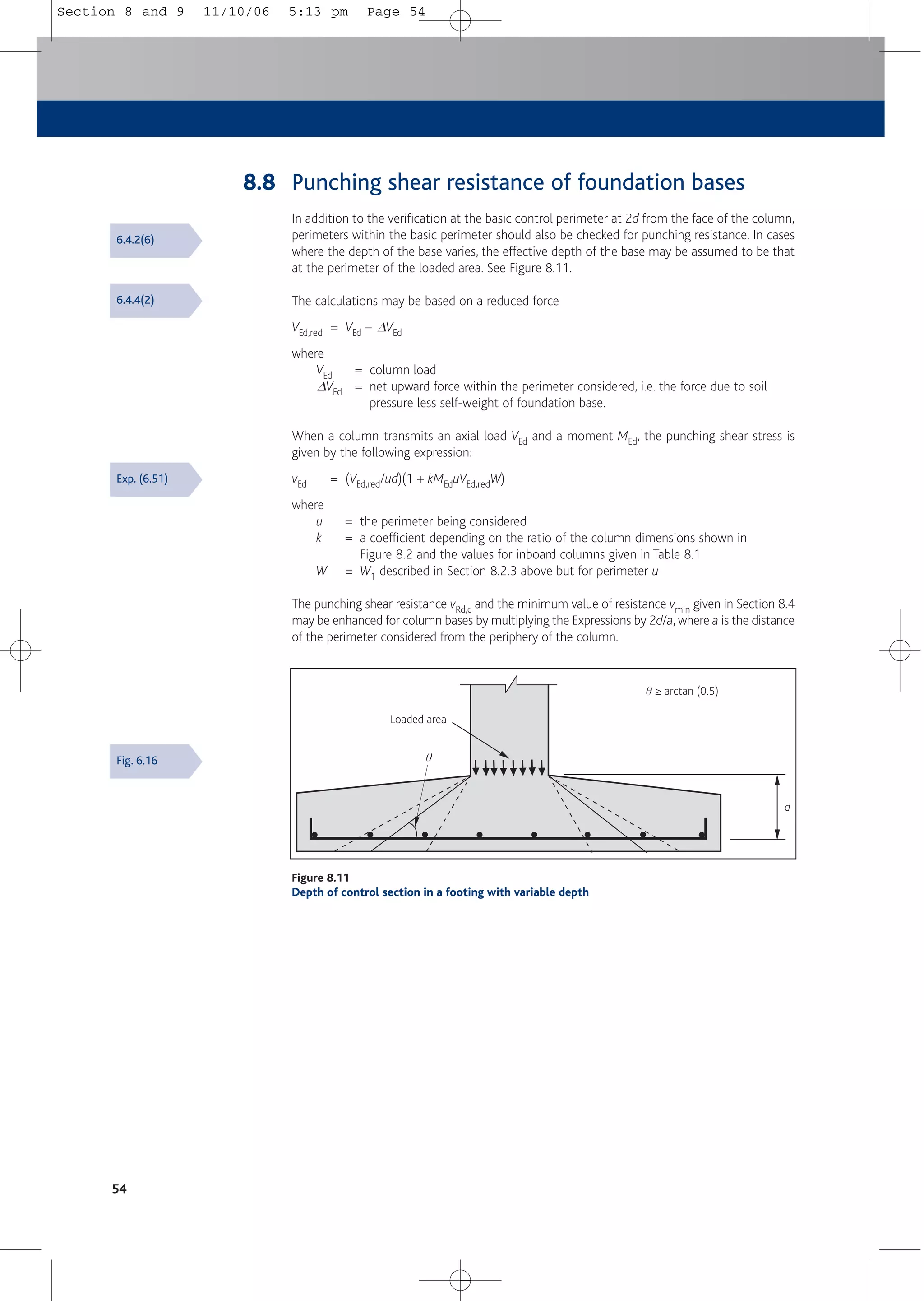
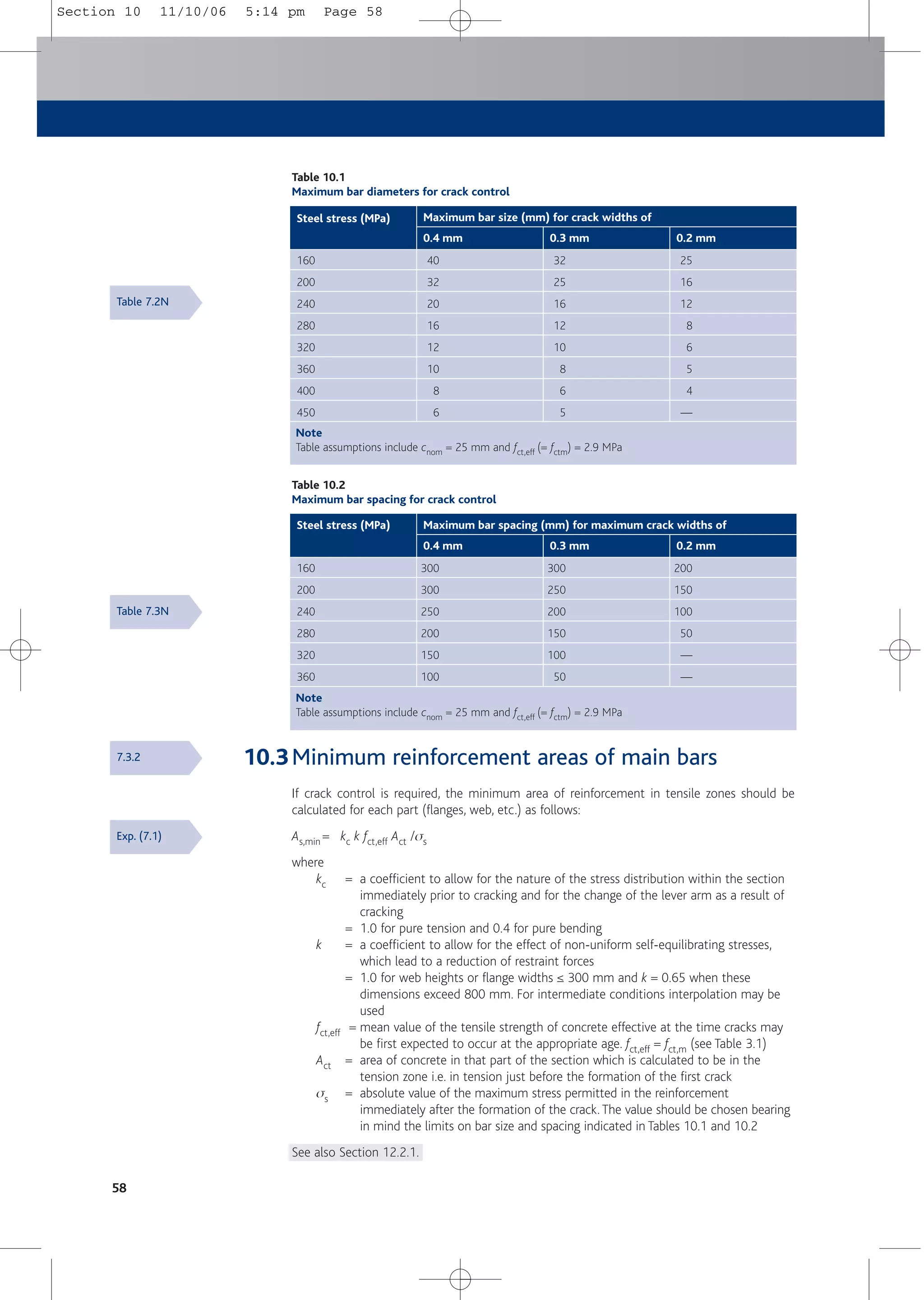
![8.2.3.2 Edge columns
a) For edge columns, with loading eccentricity perpendicular and interior to the slab edge,
b = u1/u1*
where
u1 = basic control perimeter (see Figure 8.4)
u1* = reduced control perimeter (see Figure 8.5)
b) For edge columns, with eccentricity to both axes and interior to the slab edge
b = u1/u1* + keparu1/W1
where
k = coefficient depending on the ratio of the column dimensions c1 and c2 as
shown in Figure 8.5 (see Table 8.2)
epar = eccentricity parallel to the slab edge resulting from a moment about an axis
perpendicular to the slab edge
W1 = c2
2/4 + c1c2 + 4c1d + 8d2 + πdc2
where
c1 and c2 are as Figure 8.5
b) For internal rectangular columns with loading eccentric to both axes:
b = 1 + 1.8[(ey/bz)2 + (ez/by)2]0.5
where
ey and ez = MEd/VEd along y and z axes respectively
by and bz = the dimensions of the control perimeter (see Figure 8.3)
c) For internal circular columns:
b = 1 + 0.6πe/(D + 4d)
where
D = diameter of the circular column
e = MEd/VEd
48
u1 = basic control perimeter
2d
2d
2d
2d
u1
u1
u1
by
bz
Figure 8.3
Typical basic control perimeters around loaded areas
Exp. (6.43)
Exp. (6.42)
Fig. 6.13
6.4.3(4)
Exp. (6.44)
Section 8 and 9 11/10/06 5:13 pm Page 48](https://image.slidesharecdn.com/conciseeurocode2-220718034157-f2f98aab/75/Concise_Eurocode_2-pdf-58-2048.jpg)
![Punching shear
51
2.0d
b1
b1
a1 a1
Control perimeter 2
2
2
2
a > b
b
b1
b
2.8d
≤
a1 2b
5.6d – b1
a
≤
Figure 8.7
Control perimeter for elongated supports
Loaded area Aload
Note
q = 26.6º, tan q = 0.5
hH
rcont rcont
hH
d
lH < 2.0hH lH < 2.0hH
c
Basic control section
q
q q
q
Figure 8.8
Slab with enlarged column head where lH < 2.0 hH
8.3.4 Elongated supports
For elongated supports and walls the perimeter shown in Figure 8.5a) may be used for each
end, or Figure 8.7 may be used.
8.3.5 Column heads
Where column heads are provided distinction should be made between cases where lH > 2hH
and where lH < 2hH
where
lH = projection of head from the column
hH = height of head below soffit of slab
Where lH < 2hH punching shear needs to be checked only in the control section outside the
column head (see Figure 8.8). Where lH > 2hH the critical sections both within the head and
slab should be checked (see Figure 8.9).
ENV 1992-1-1:
4.3.4.2.1(2)[22]
Fig. 6.17
Section 8 and 9 11/10/06 5:13 pm Page 51](https://image.slidesharecdn.com/conciseeurocode2-220718034157-f2f98aab/75/Concise_Eurocode_2-pdf-61-2048.jpg)
![Punching shear
53
8.6 Punching shear resistance adjacent to columns
At the column perimeter, u0, the punching shear stress should be checked to ensure that
vEd = bVEd/u0d ≤ vRd,max
where
b = factor dealing with eccentricity (see Section 8.2)
VEd = applied shear force
d = mean effective depth
u0 = 2(c1 + c2) for interior columns
= c2 + 3d ≤ c2 + 2c1 for edge columns
= 3d ≤ c2 + 2c1 for corner columns
where
c1 = column depth (for edge columns, measured perpendicular to the free edge)
c2 = column width as illustrated in Figure 8.5
vRd,max = 0.5vfcd
where
v = 0.6 [1 – (fck/250)]
At the column perimeter, vRd,max = vRd,max for cot q = 1.0 given in Table 7.2.
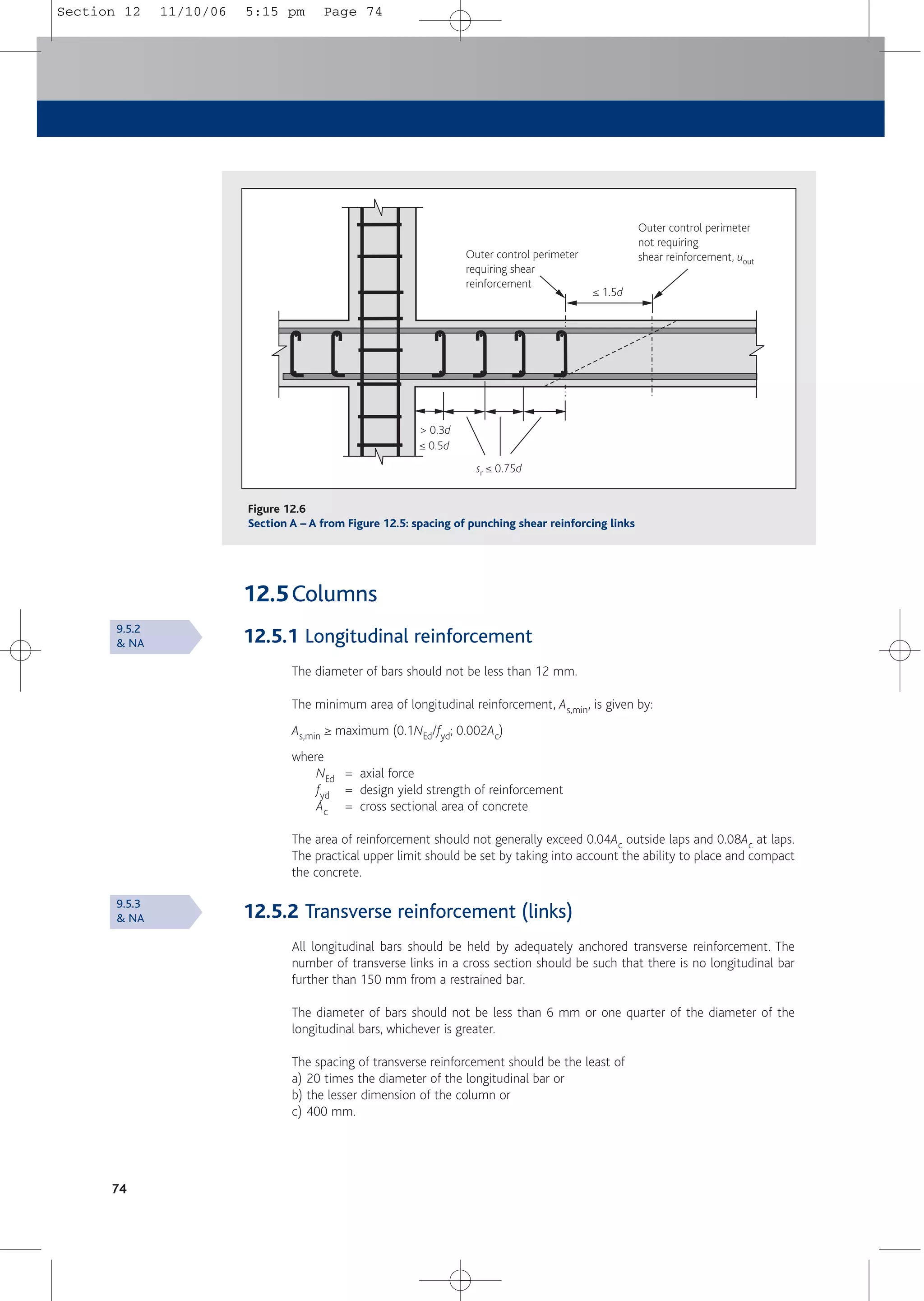
8.7 Control perimeter where shear reinforcement is no
longer required, uout
Shear reinforcement is not required at a perimeter where the shear stress due to the effective
shear force does not exceed vRd,c. The outermost perimeter of shear reinforcement should be
placed at a distance not greater than 1.5d within the perimeter where reinforcement is no
longer required. See Figures 8.10, 12.5 and 12.6.
Perimeter uout,ef
Perimeter uout
≤ 2d
1.5d
> 2d
1.5d
d
d
Figure 8.10
Control perimeters at internal columns
6.4.5(3)
6.4.5(4)
& NA
Fig. 6.22
Section 8 and 9 11/10/06 5:13 pm Page 53](https://image.slidesharecdn.com/conciseeurocode2-220718034157-f2f98aab/75/Concise_Eurocode_2-pdf-63-2048.jpg)
![Torsion
9 Torsion
9.1 General
Torsional resistance should be verified in elements that rely on torsion for static equilibrium. In
statically indeterminate building structures in which torsion arises from consideration of
compatibility and the structure is not dependent on torsion for stability, it will normally be
sufficient to rely on detailing rules for minimum reinforcement to safeguard against excessive
cracking, without the explicit consideration of torsion at ULS.
In Eurocode 2, torsional resistance is calculated by modelling all sections as equivalent thin-
walled sections. Complex sections, such as T-sections are divided into a series of sub-sections
and the total resistance is taken as the sum of the resistances of the individual thin-walled sub-
sections.
The same strut inclination q should be used for modelling shear and torsion.The limits for cot q
noted in Section 7 for shear also apply to torsion.
9.2 Torsional resistances
The maximum torsional capacity of a non-prestressed section is
TRd,max = 2mfcdAktef,i sin q cos q
where
m = 0.6 [1– (fck/250)]
Ak = area enclosed by the centre lines of connecting walls including the inner hollow
area (see Figure 9.1)
tef,i = effective wall thickness (see Figure 9.1). It may be taken as A/u but should not be
taken as less than twice the distance between edge (the outside face of the
member) and centre of the longitudinal reinforcement. For hollow sections the
real thickness is an upper limit
q = angle of the compression strut
55
Centre line
Cover
Outer edge of
effective cross section,
circumference, u
tef
zi
TEd
tef/2
Figure 9.1
Notations used in Section 9
6.3.1
6.3.2
Exp. (6.30)
Fig. 6.11
Section 8 and 9 11/10/06 5:13 pm Page 55](https://image.slidesharecdn.com/conciseeurocode2-220718034157-f2f98aab/75/Concise_Eurocode_2-pdf-65-2048.jpg)
![The torsional capacity of a solid rectangular section with shear reinforcement on the outer
periphery TRd,max may be deduced from the general expression:
TRd,max = 2vfcd k2b3 sin q cos q
where
k2 = coefficient obtained from Table 9.1
b = breadth of the section (< h, depth of section)
Torsional resistance governed by the area of closed links is given by:
TRd = Asw/s) = TEd/(2Ak cot q) fywd
where
Asw = area of link reinforcement
fyw,d = design strength of the link reinforcement
s = spacing of links
Additional longitudinal reinforcement distributed around the periphery of the section should be
provided and the area of this reinforcement should be obtained from the following expression:
2Asl = TEdukcot q/(fyd2Ak) = (Asw/s) uk cot2 q
where
TEd = applied design torsion
uk = perimeter of the area Ak
Assuming fyd = fywd
9.3 Combined torsion and shear
In solid sections the following relationship should be satisfied:
(TEd /TRd,max) + (VEd/VRd, max) ≤ 1.0
where
TRd,max = 2mfcdAktef,i sin q cos q as in Section 9.2.
VRd,max = vwzmfcd(cot q + cot a)/(1 + cot2 q) as in Section 7.3.2.
56
Table 9.1
Values of k2
h/b 1
k2 0.141
2
0.367
3
0.624
4
0.864
Exp. (6.28)
ENV 1992-1-1
Exp. (4.43)[21]
Exp. (6.29)
Section 8 and 9 11/10/06 5:13 pm Page 56](https://image.slidesharecdn.com/conciseeurocode2-220718034157-f2f98aab/75/Concise_Eurocode_2-pdf-66-2048.jpg)
![Serviceability
57
10 Serviceability
10.1Introduction
The common serviceability limit states considered are:
■ Stress limitation.
■ Crack control.
■ Deflection control.
For the UK, explicit checks on concrete stresses at serviceability are not normally required,
unless lower values for partial factor gc than those shown in Section 2, Table 2.3 are used.
Similarly, the steel stress need not be checked unless the values for gs are smaller than those
indicated.
In compression members, the provision of links in accordance with detailing rules ensures that
there is no significant longitudinal cracking.
Cracking and deflection may be verified by either following calculation procedures or by
observing the rules for bar diameters and bar spacing and span-to-effective-depth ratios. This
publication does not consider calculation methods.
10.2Control of cracking
Cracks may be limited to acceptable widths by the following measures:
■ Provide a minimum amount of reinforcement, so that the reinforcement does not yield
immediately upon formation of the first crack (see Section 10.3).
■ Where restraint is the main cause of cracking, limit the bar diameter to that shown in
Table 10.1. In this case any level of steel stress may be chosen but the chosen value must
then be used in the calculation of As,min and the size of the bar should be limited as
shown.
■ Where loading is the main cause of cracking, limit the bar diameter to that shown in
Table 10.1 or limit the bar spacing to that shown in Table 10.2.
When using either table the steel stress should be calculated on the basis of a cracked
section under the relevant combination of actions.
In the absence of specific requirements (e.g. water-tightness), the limiting calculated crack
width wmax may be restricted to 0.3 mm in all exposure classes under quasi-permanent load
combinations. In the absence of specific requirements for appearance, this limit may be relaxed
to, say, 0.4 mm for exposure classes X0 and XC1.
In building structures subjected to bending without significant axial tension, specific measures
to control cracking are not necessary where the overall depth of the member does not exceed
200 mm.
7.2, NA &
PD 6687 [7]
7.3.3(2)
7.3.1(5)
& NA
Section 10 11/10/06 5:14 pm Page 57](https://image.slidesharecdn.com/conciseeurocode2-220718034157-f2f98aab/75/Concise_Eurocode_2-pdf-67-2048.jpg)
![Serviceability
59
10.4Minimum area of shear reinforcement
10.4.1 Beams
The minimum area of shear reinforcement in beams Asw,min should be calculated from the
following expression:
Asw,min/(sbw sin a) ≥ 0.08 fck
0.5/fyk
where
s = longitudinal spacing of the shear reinforcement
bw = breadth of the web member
a = angle of the shear reinforcement to the longitudinal axis of the member.
For vertical links sin a = 1.0.
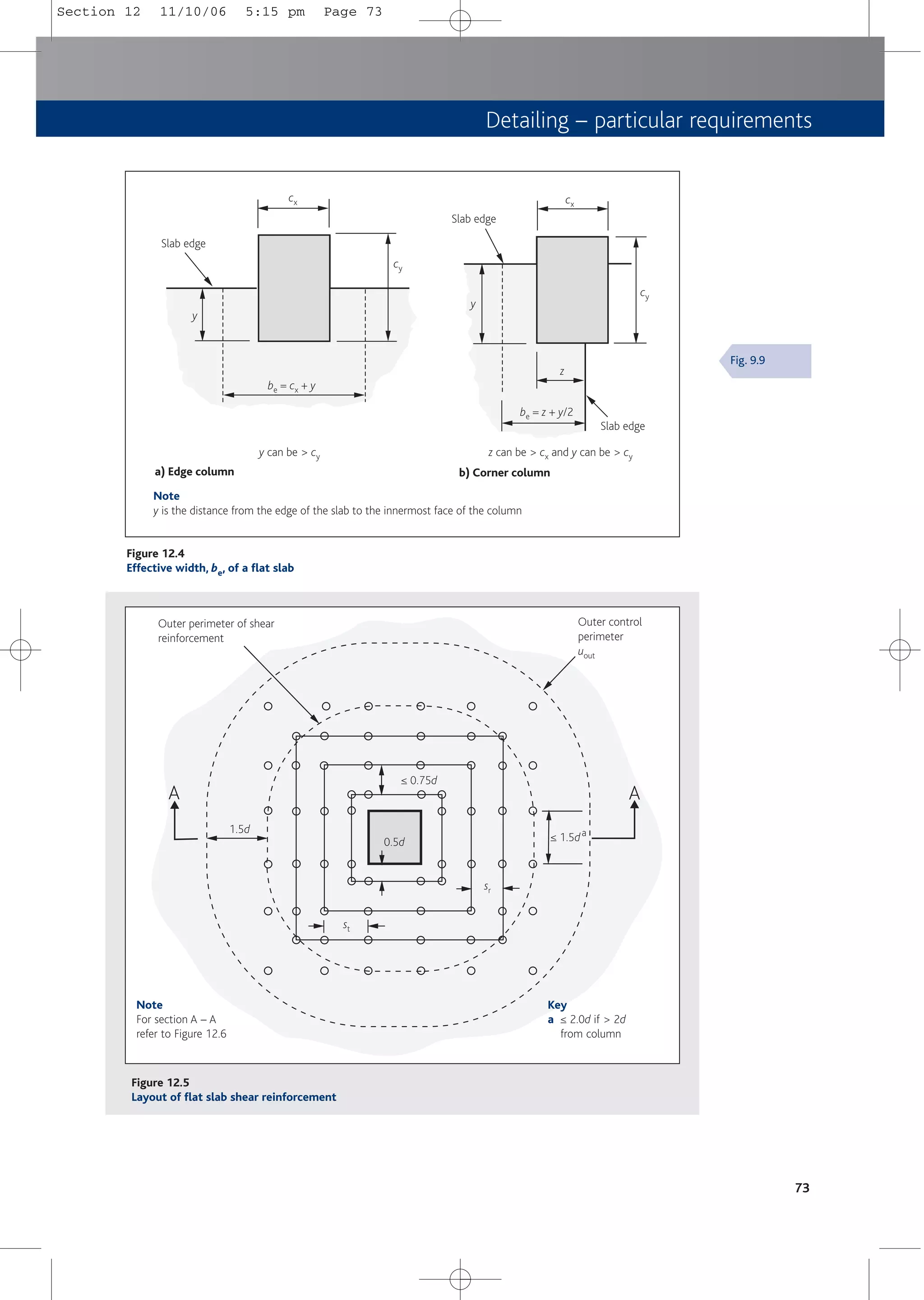
10.4.2 Flat slabs
In slabs where punching shear reinforcement is required, the minimum area of a link leg, Asw,min
should be calculated from the following expression:
Asw,min (1.5 sin a + cos a)/(sr st) ≥ 0.08 fck
0.5/fyk
where
sr and st = spacing of shear reinforcement in radial and tangential directions respectively
(see Figure 12.5)
10.5Control of deflection
10.5.1 General
The deflection of reinforced concrete building structures will normally be satisfactory if the
beams and slabs are sized using the span-to-effective-depth ratios. More sophisticated
methods (as discussed in TR58[23]) are perfectly acceptable but are beyond the scope of this
publication.
10.5.2 Basic span-to-effective-depth ratios
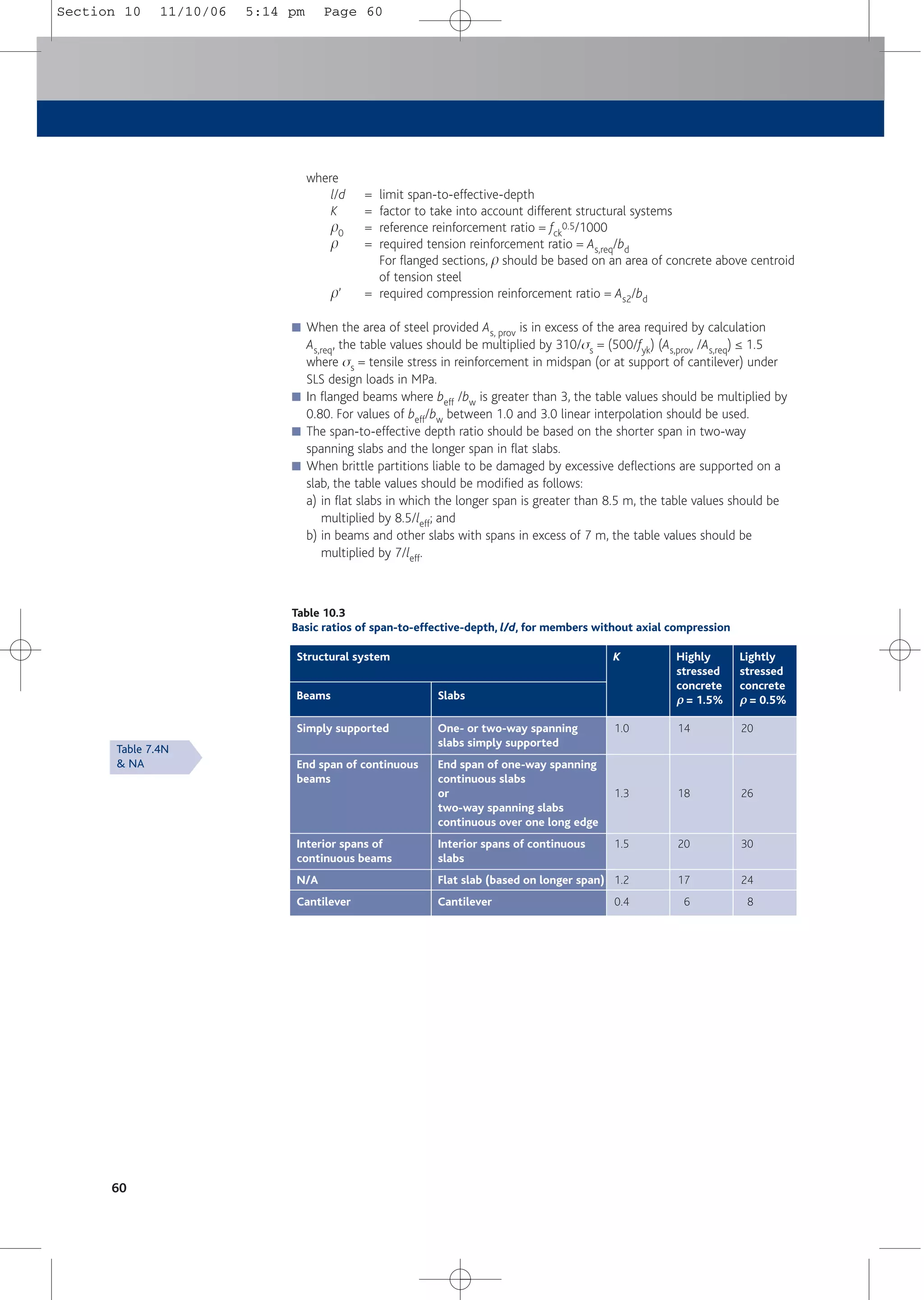
Basic span-to-effective-depth ratios are given in Table 10.3.
This table has been drawn up on the assumption that the structure will be subject to its design
loads only when the concrete has attained the strength assumed in design, fck. If the structure
is to be loaded before the concrete attains fck, then a more detailed appraisal should be
undertaken to take into account the loading and the strength of the concrete at the time of
loading.
Table 10.3 is subject to the following conditions of use:
■ Values for span-to-effective-depth ratios have been calculated using the criterion that the
deflection after construction is span/500 for quasi-permanent loads.
■ Table values apply to reinforcement with fyk = 500 MPa, ss = 310 MPa, and concrete class
C30/37 (fck = 30).
■ Values of basic span-to-effective-depth ratios may be calculated from the formulae:
l/d = K[11 + 1.5fck
0.5p0/p + 3.2 fck
0.5(p0/p – 1)1.5] if p0 ≤ p
or
l/d = K[11 + 1.5fck
0.5p0/(p – p') + fck
0.5(p'/p0)0.5/12] if p0 > p
9.2.2(5)
& NA
9.4.3(2)
7.4.1, 7.4.2
& NA
7.4.3
PD 6687[7]
7.4.2(2)
Exp. (7.16a)
Exp. (7.16b)
Section 10 11/10/06 5:14 pm Page 59](https://image.slidesharecdn.com/conciseeurocode2-220718034157-f2f98aab/75/Concise_Eurocode_2-pdf-69-2048.jpg)
![Detailing – general requirements
61
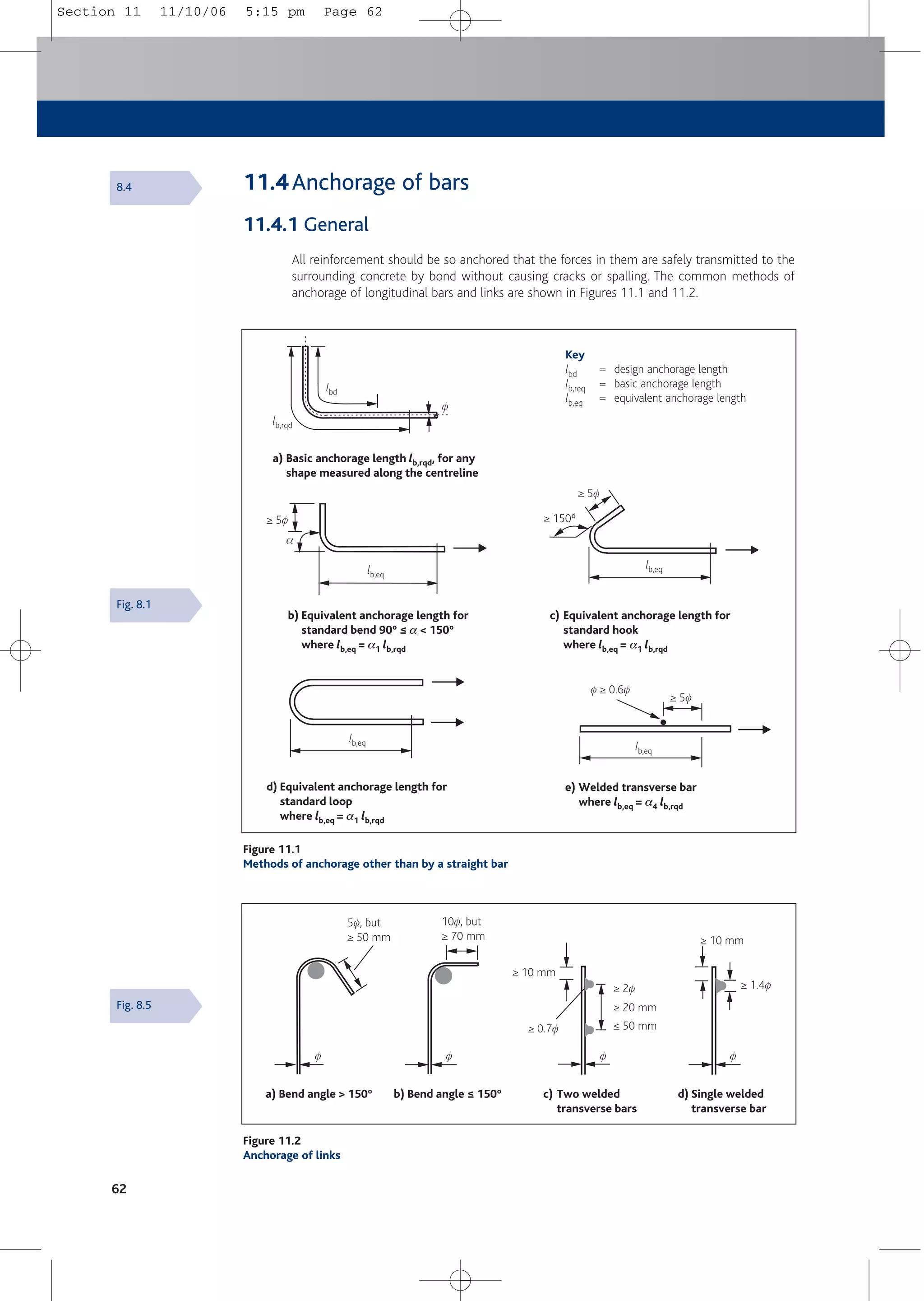
11 Detailing – general requirements
11.1General
These requirements for detailing apply to ribbed reinforcement and welded mesh used in
structures subject predominantly to static loading.
The rules apply to single bars and bundled bars for which an equivalent diameter fn = f(nb)0.5
should be used in the calculations. In this Expression, nb is the number of bars in the bundle. A
value for nb should be limited to four vertical bars in compression and in lapped joints, and to
three in all other cases. The value of fn should be less than or equal to 55 mm.
The clear distance between (and the cover to) bundled bars should be measured from the
actual external contour of the bundled bars. Bars are allowed to touch one another at laps and
they need not be treated as bundled bars under these conditions.
11.2Spacing of bars
Bar spacing should be such that concrete can be placed and compacted satisfactorily for the
development of bond.
The clear distance between individual bars and between horizontal layers of bars should not be
less than the bar diameter, the aggregate size + 5 mm, or 20 mm, whichever is the greatest.
Where bars are in a number of layers, bars in each layer should be located above each other.
The spacing between the resulting columns of bars should be sufficient to allow access for
vibrators to give good compaction.
11.3Mandrel sizes for bent bars
The diameter to which a bar is bent should be such as to avoid damage to the reinforcement
and crushing of concrete inside the bend of the bar. To avoid damage to reinforcement the
mandrel size is as follows:
4f for bar diameter f ≤ 16 mm
7f for bar diameter f > 16 mm
20f for mesh bent after welding where transverse bar is on or within 4f of the bend.
Otherwise 4f or 7f as above. Welding must comply with ISO/FDIS 17660-2[24].
The mandrel diameter fm to avoid crushing of concrete inside the bend need not be checked if:
■ Diameters noted above are used; and
■ Anchorage of the bar does not require a length more than 5f past the end of the bend; and
■ The bar is not positioned at an edge and there is a cross bar (of diameter ≥ f) inside the bend.
Otherwise the following minimum mandrel diameter fm should be used:
fm ≥ Fbt ((1/ab) + (1/(2f))/ fcd
where
Fbt = tensile force in the bar at the start of the bend caused by ultimate loads
ab = half the centre to centre spacing of bars (perpendicular to the plane of the
bend). For bars adjacent to the face of the member, ab = cover + 0.5f
fcd = acc fck /gc
where
acc = 1.0 (treated as a local bearing stress)
fck = characteristic cylinder strength. Note fck is limited to 50 MPa
8.1
8.9.1
8.2
8.3
Table 8.1N
& NA
3.1.6(1)
& NA
Section 11 11/10/06 5:15 pm Page 61](https://image.slidesharecdn.com/conciseeurocode2-220718034157-f2f98aab/75/Concise_Eurocode_2-pdf-71-2048.jpg)
![12.8Bored piles
Bored piles not exceeding 600 mm in diameter should have the minimum reinforcement shown
in Table 12.2. A minimum of six longitudinal bars with diameter of at least 16 mm should be
provided with a maximum spacing of 200 mm around the periphery of the pile. The detailing
should comply with BS EN 1536[25].
76
Table 12.2
Longitudinal reinforcement in cast-in-place bored piles
Area of cross section of the pile (Ac)
Minimum area of longitudinal
reinforcement (As,bpmin)
Ac ≤ 0.5 m2
≥ 0.005Ac
0.5 m2 ≤ 1.0 m2
≥ 25 cm2
Ac > 1.0 m2
≥ 0.0025Ac
9.8.5
& NA
Section 12 11/10/06 5:15 pm Page 76](https://image.slidesharecdn.com/conciseeurocode2-220718034157-f2f98aab/75/Concise_Eurocode_2-pdf-86-2048.jpg)
![Tying systems
77
13 Tying systems
13.1General
This Section should be considered in conjunction with the UK Building Regulations[26] and the
relevant Approved Documents, which classify the buildings based on the use of the building
and also specify the types of ties that are required in each class. The forces should be
considered as accidental loads.
All structures should have a suitable tying system to prevent disproportionate collapse caused
by human error or the accidental removal of a member or limited part of the structure or the
occurrence of localised damage. This requirement will be satisfied if the following rules are
observed.
The structure should have:
■ Peripheral ties.
■ Internal ties.
■ Horizontal ties at columns/walls.
■ Vertical ties.
In the design of ties, reinforcement should be provided to carry the tie forces noted in this Section,
assuming that the reinforcement acts at its characteristic strength. Reinforcement provided for
other purposes may be regarded as providing part or the whole of the required reinforcement.
All ties should be effectively continuous and be anchored at their ends.
13.2Peripheral ties
At each floor and roof level, an effectively continuous tie should be provided within 1.2 m from
the edge. Structures with internal edges (e.g. atria and courtyards) should also have similar
peripheral ties.
The peripheral tie should be able to resist a tensile force of:
Ftie,per = (20 + 4n0) kN ≤ 60 kN where n0 = number of storeys
13.3Internal ties
At each floor and roof level, internal ties should be provided in two directions approximately at
right angles.
The internal ties, in whole or in part, may be spread evenly in slabs or may be grouped at or in
beams, walls or other positions. If located in walls, the reinforcement should be within 0.5 m of
the top or bottom of the floor slabs.
In each direction the tie needs to be able to resist a force, which should be taken as:
Ftie,int = (1/7.5)(gk + qk)(lr/5)Ft ≥ Ft
where
(gk + qk) = average permanent and variable floor actions (kN/m2)
lr = greater of the distances (in m) between centres of the columns, frames or
walls supporting any two adjacent floor spans in the direction of the tie
under consideration
Ft = (20 + 4n0) ≤ 60 kN (n0 is the number of storeys)
The maximum spacing of internal ties should be limited to 1.5lr.
9.10.1
9.10.2.2
& NA
9.10.2.3
& NA
Section 13 11/10/06 5:16 pm Page 77](https://image.slidesharecdn.com/conciseeurocode2-220718034157-f2f98aab/75/Concise_Eurocode_2-pdf-87-2048.jpg)
![13.4Ties to columns and walls
Columns and walls at the edge and corner of the structure should be tied to each floor and roof.
In corner columns and walls ties should be provided in two directions.
The tie should be able to resist a force of:
Ftie, fac = Ftie, col = maximum (2Ft; lsFt/2.5; 0.03 NEd)
where
Ftie,fac = in kN/m run of wall
Ftie,col = in kN/column.
Ft = defined in Section 13.3 above
ls = floor to ceiling height (in metres)
NEd = total design ultimate vertical load in wall or column at the level considered
Tying of external walls is required only if the peripheral tie is not located within the wall.
13.5Vertical ties
BS EN1992-1-1 requires vertical ties in panel buildings of five storeys or more.
However, relevant current UK Building Regulations require such ties in all buildings that fall
into Class 2B and 3 as defined in Section 5 of Approved Document A[27] (see Table 13.1). In
all such buildings vertical ties should be provided in columns and/or walls.
Each column and wall carrying vertical load should be tied continuously from the lowest to the
highest level.The tie should be capable of resisting the load received by the column or wall from
any one storey under accidental design situation i.e. using Exp. (6.11b) in BS EN 1990. See
Table 2.2e.
Where such ties are not provided either:
■ The vertical member should be demonstrated for ‘non-removability’. Non-removability
may be assumed if the element and its connections are capable of withstanding a design
action at limit state of 34 kN/m2 in any direction over the projected area of the member
together with the reactions from attached components, which themselves are subject to
a loading of 34 kN/m2. These reactions may be limited to maximum reaction that can be
transmitted; or
■ Each element should be considered to be removed one at a time and an alternative path
demonstrated.
Where a column or wall is supported at its lowest level by an element other than a
foundation, alternative load paths should be provided in the event of the accidental loss of
this element.
78
9.10.2.4
& NA
9.10.2.5
AD A[27]
PD 6687[7]
9.10.2.5(2)
Section 13 11/10/06 5:16 pm Page 78](https://image.slidesharecdn.com/conciseeurocode2-220718034157-f2f98aab/75/Concise_Eurocode_2-pdf-88-2048.jpg)
![Tying systems
79
Table 13.1
Building classes from Approved Document A – structure (2004 edition)[27]
Class Building type and occupancy
1
2A
2B
3
Houses not exceeding 4 storeys
Agricultural buildings
Buildings into which people rarely go, provided no part of the building is closer to another
building, or area where people do go, than a distance of 1.5 times the building height
5 storey single occupancy houses
Hotels not exceeding 4 storeys
Flats, apartments and other residential buildings not exceeding 4 storeys
Offices not exceeding 4 storeys
Industrial buildings not exceeding 3 storeys
Retailing premises not exceeding 3 storeys of less than 2000 m2 floor area in each storey
Single storey educational buildings
All buildings not exceeding 2 storeys to which members of the public are admitted and which
contain floor areas not exceeding 2000 m2 at each storey
Hotels, flats, apartments and other residential buildings greater than 4 storeys but not
exceeding 15 storeys
Educational buildings greater than 1 storey but not exceeding 15 storeys
Retailing premises greater than 3 storeys but not exceeding 15 storeys
Hospitals not exceeding 3 storeys
Offices greater than 4 storeys but not exceeding 15 storeys
All buildings to which members of the public are admitted which contain floor areas exceeding
2000 m2 but less than 5000 m2 at each storey
Car parking not exceeding 6 storeys
All buildings defined above as Class 2A and 2B that exceed the limits on area and/or number
of storeys
Grandstands accommodating more than 5000 spectators
Buildings containing hazardous substances and/or processes
Notes
1 For buildings intended for more than one type of use, the class should be that pertaining to the most
onerous type.
2 In determining the number of storeys in a building, basement storeys may be excluded provided such
basement storeys fulfil the robustness requirements of Class 2B buildings.
Section 13 11/10/06 5:16 pm Page 79](https://image.slidesharecdn.com/conciseeurocode2-220718034157-f2f98aab/75/Concise_Eurocode_2-pdf-89-2048.jpg)
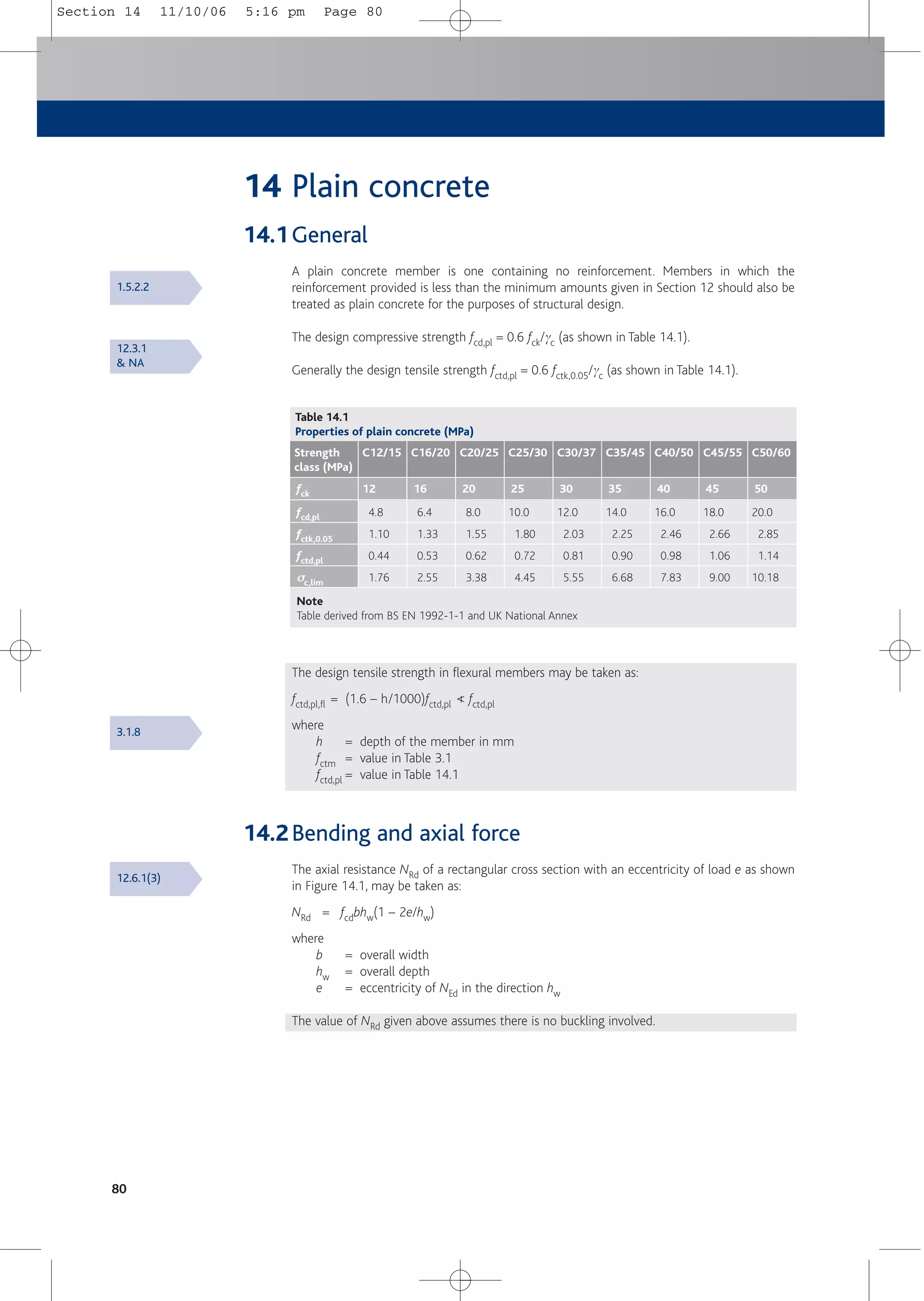
![Plain concrete
81
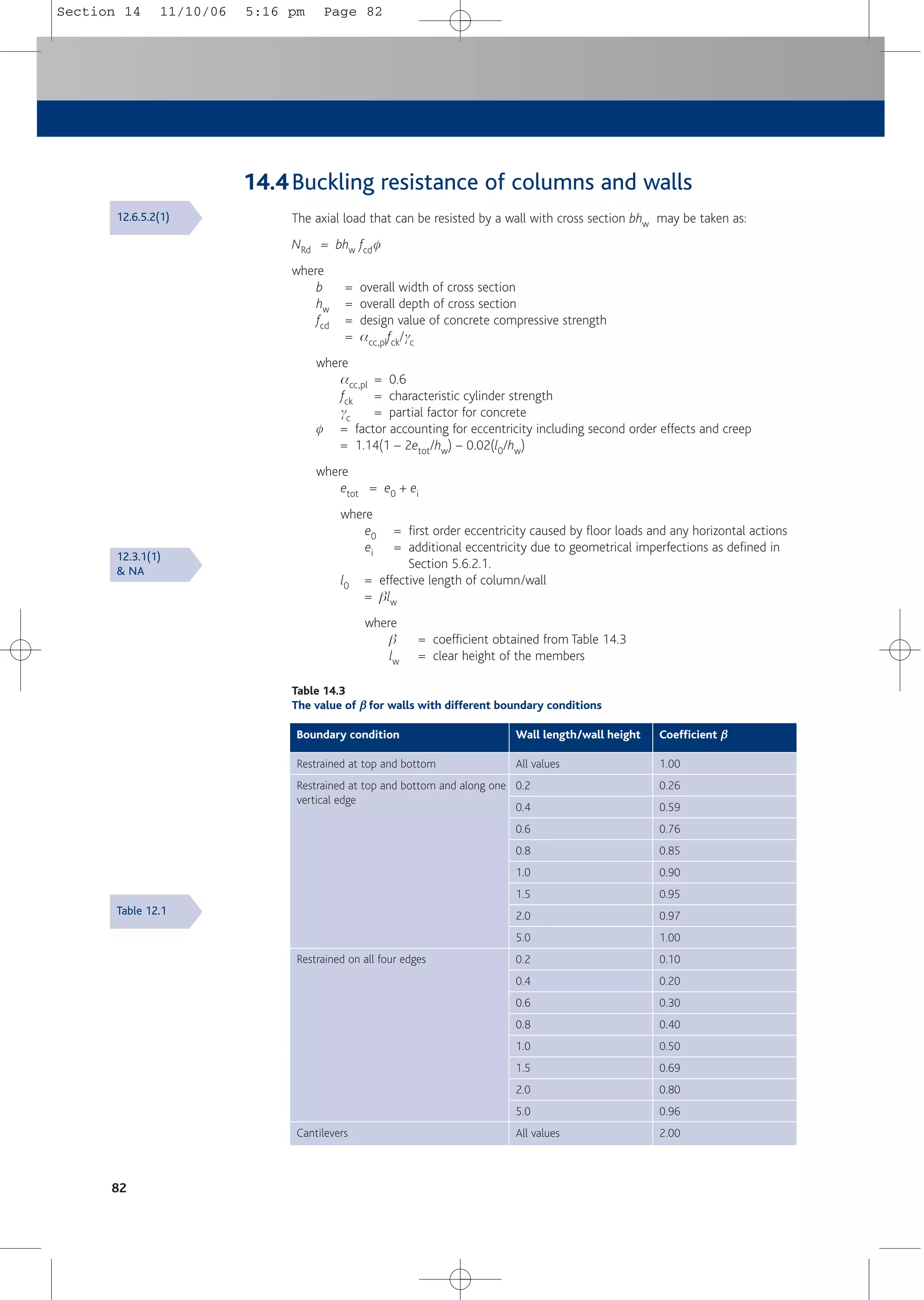
14.3Shear resistance
It should be verified that
tcp = shear stress = 1.5 VEd/Acc ≤ fcvd
where
Acc = cross sectional area
VEd = shear force
fcvd = concrete design strength in shear and compression and is dependent on the
level of axial stress (see Table 14.2)
= (fctd,pl
2 + scpfctd,pl)0.5 when scp ≤ sc,lim
= [fctd,pl
2 + scpfctd,pl – 0.25(scp – sc,lim)2]0.5 when scp > sc,lim
where
scp = NEd/Acc when NEd = normal force
sc,lim= fcd,pl – 2[fctd,pl(fctd,pl + fcd,pl)]0.5 (see Table 14.1)
Table 14.2
Shear resistance fcvd of plain concrete (MPa)
0.0
1.0
2.0
3.0
4.0
5.0
6.0
7.0
8.0
9.0
10.0
0.44
0.80
1.03
1.06
0.84
σ
σcp (MPa)
12
fck
0.53
0.90
1.16
1.35
1.38
1.21
0.72
16
0.62
1.00
1.27
1.50
1.66
1.68
1.54
1.20
20
0.72
1.11
1.40
1.63
1.84
2.01
2.06
1.98
1.76
1.34
0.00
25
0.81
1.21
1.51
1.76
1.98
2.17
2.34
2.41
2.38
2.23
1.96
30
0.90
1.31
1.61
1.87
2.10
2.30
2.49
2.66
2.75
2.75
2.65
35
0.98
1.40
1.71
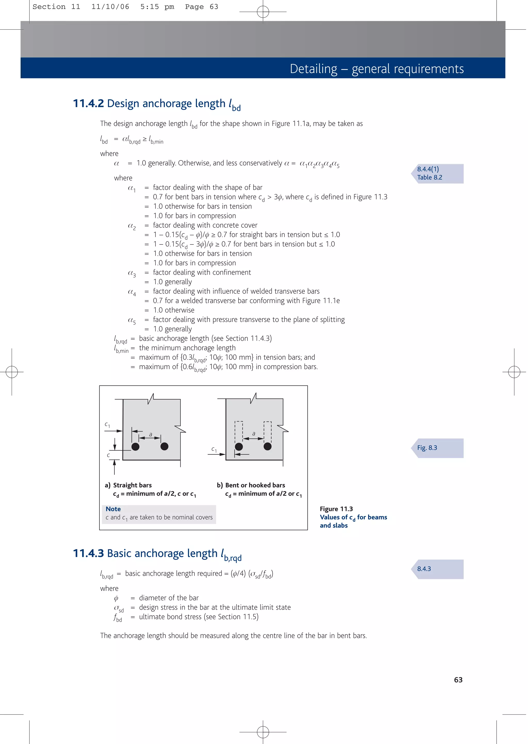
1.98
2.21
2.42
2.62
2.80
2.97
3.08
3.10
40
1.06
1.48
1.80
2.08
2.32
2.54
2.74
2.93
3.10
3.27
3.39
45
1.14
1.56
1.89
2.17
2.42
2.65
2.85
3.05
3.23
3.40
3.56
50
Note
Table derived from BS EN 1992-1-1 and National Annex
lw
b
e
NEd
hw
L
c
Figure 14.1
Notation for plain
walls
12.6.3(2)
& NA
Fig. 12.1
Section 14 11/10/06 5:16 pm Page 81](https://image.slidesharecdn.com/conciseeurocode2-220718034157-f2f98aab/75/Concise_Eurocode_2-pdf-91-2048.jpg)
![84
15 Design aids
The following text, tables and figures have been derived from Eurocode 2 and are provided as
an aid to designers in the UK.
15.1Design values of actions
For the ULS of strength (STR) where there is a single variable action use either:
■ 1.35Gk + 1.5Qk Exp. (6.10) from Eurocode[5]
or the worse case of
■ 1.35Gk + y01.5Qk Exp. (6.10a)
■ 1.25Gk + 1.5Qk Exp. (6.10b)
where y0 = 1.0 for storage, 0.5 for snow but otherwise 0.7, see Table 2.2.
In most cases Exp. (6.10b) will be appropriate, except for storage where the use of Exp. (6.10a)
is likely to be more onerous.
For the SLS of deformation, quasi-permanent loads should be applied. These are 1.0Gk + y2Qk
where y2 is dependent on use, e.g. 0.3 for offices and residential and 0.8 for storage. Again, see
Table 2.2.
15.2Values of actions
The values of actions (i.e. loads) are defined in Eurocode 1, BS EN 1991[6].The parts of Eurocode 1
are given in Table 15.1.These values are taken as characteristic values. At the time of publication,
the UK National Annexes to these parts are in various states of readiness.
As PD 6687[7] makes clear, until the appropriate European standards become available,
designers may consider using current practice or current British Standards in conjunction with
BS EN 1992, provided they are compatible with BS EN 1992 and that the resulting reliability is
acceptable.
BS EN 1991-1-1 states that the density of concrete is 24 kN/m3, reinforced concrete, 25 kN/m3
and wet reinforced concrete, 26 kN/m3.
Table 15.1
The parts of Eurocode 1[6]
Reference Title
BS EN 1991-1-1
BS EN 1991-1-2
BS EN 1991-1-3
BS EN 1991-1-4
BS EN 1991-1-5
BS EN 1991-1-6
BS EN 1991-1-7
BS EN 1991-2
BS EN 1991-3
BS EN 1991-4
Densities, self-weight and imposed loads
Actions on structures exposed to fire
Snow loads
Wind actions
Thermal actions
Actions during execution
Accidental actions due to impact and explosions
Traffic loads on bridges
Actions induced by cranes and machinery
Actions in silos and tanks
Section 2.3.4
Section 2.3.4
Section 2.3.4
Section 15 11/10/06 5:17 pm Page 84](https://image.slidesharecdn.com/conciseeurocode2-220718034157-f2f98aab/75/Concise_Eurocode_2-pdf-94-2048.jpg)
![Design aids
85
15.3Analysis
Analysis is dealt with in Section 5. Where appropriate the coefficients given in Tables 15.2 and
15.3 can be used to determine design moments and shear for slabs and beams at ULS.
Table 15.2
Coefficients for use with one-way spanning slabs to Eurocode 2
Moment
Shear
0.0
0.40
Coefficient
End support/slab connection Internal supports and spans
Location
Pinned end support
Outer
support
Near
middle
of end
span
Outer
support
Near
middle
of end
span
At 1st
interior
support
At
middle
of
interior
spans
At
interior
supports
Continuous
0.086
—
– 0.04
0.46
0.075
—
– 0.086
0.60:0.60
0.063
—
– 0.063
0.50:0.50
Conditions
Applicable to one-way spanning slabs where the area of each bay exceeds 30 m2, Qk ≤ 1.25Gk and qk ≤
5 kN/m2, substantially uniform loading (at least 3 spans, minimum span ≥ 0.85 maximum (design) span.
Design moment = coeff x n x span2 and design shear = coeff x n x span where n is a UDL with a single
variable action = gGgk + ygQqk where gk and qk are characteristic permanent and variable actions in
kN/m.
Basis:Yield Line design (assumed 20% redistribution[14], see Section 4.6.9.)
Table 15.3
Coefficients for use with beams (and one-way spanning slabs) to Eurocode 2
Moment gk and qk
Moment gk
Moment qk
Shear
25% spana
—
—
0.45
Outer
support
Near middle
of end span
At 1st
interior
support
At middle
of interior
spans
At interior
supports
—
0.090
0.100
—
0.094
—
—
0.63:0.55
—
0.066
0.086
—
0.075
—
—
0.50:0.50b
Conditions
For beams and slabs, 3 or more spans. (They may also be used for 2 span beams but support moment
coefficient = 0.106 and internal shear coefficient = 0.63 both sides).
Generally Qk ≤ Gk, and the loading should be substantially uniformly distributed. Otherwise special
curtailment of reinforcement is required.
Minimum span ≥ 0.85 x maximum (and design) span.
Design moment at supports = coeff x n x span2 or
in spans = (coeff gk x gGgk + coeff qk x ygQqk) x span2.
Design shear at centreline of supports = coeff x n x span where n is a UDL with a single variable action
= gGgk + ygQqk where gk and qk are characteristic permanent and variable actions in kN/m.
gG and ygQ are dependent on use of BS EN 1990 Exp. (6.10), Exp. (6.10a) or Exp. (6.10b). See Section
15.1.
Basis: All- and alternate-spans-loaded cases as UK National Annex and 15% redistribution at supports.
Key
a At outer support ‘25% span’ relates to the UK Nationally Determined Parameter for BS EN 1992-1-1
9.2.1.2(1) for minimum percentage of span bending moment to be assumed at supports in beams in
monolithic construction. 15% may be appropriate for slabs (see BS EN 1992-1-1 Cl 9.3.1.2).
b For beams of five spans, 0.55 applies to centre span.
Sections 5.3
& 5.4
Coefficient Location
Section 15 11/10/06 5:17 pm Page 85](https://image.slidesharecdn.com/conciseeurocode2-220718034157-f2f98aab/75/Concise_Eurocode_2-pdf-95-2048.jpg)
![86
15.4Design for bending
■ Determine whether K ≤ K’ or not (i.e. whether under-reinforced or not).
where
K = MEd/(bd2fck)
where
d = effective depth = h – cover – f/2
b = width of section
K' may be determined from Table 15.4 and is dependent on the redistribution ratio used.
■ If K ≤ K', section is under-reinforced.
For rectangular sections:
As1 = MEd/fydz
where
As1 = area of tensile reinforcement
MEd = design moment
fyd = fyk/gs = 500/1.15 = 434.8 MPa
z = d[0.5 + 0.5(1 – 3.53K)0.5] ≤ 0.95d
Values of z/d (and x/d) may be taken from Table 15.5
For flanged beams where x < 1.25hf,
As1 = MEd/fydz
where x = depth to neutral axis.Values of x/d may be taken from Table 15.5
hf = thickness of flange
For flanged beams where x ≥ 1.25hf, refer to How to design concrete structures using
Eurocode 2: Beams[28]
■ If K > K', section is over-reinforced and requires compression reinforcement.
As2 = (MEd – M’)/fsc(d – d2)
where
As2 = compression reinforcement
M’ = K’bd2fck
fsc = 700(xu– d2)/xu ≤ fyd
where
d2 = effective depth to compression reinforcement
xu = (d – 0.4)d
where
d = redistribution ratio
Total area of steel As1 = M’/(fydz) + As2 fsc/fyd
15.5Design for beam shear
15.5.1 Requirement for shear reinforcement
If vEd > vRd,c then shear reinforcement is required
where
vEd = VEd/bwd, for sections without shear reinforcement (i.e. slabs)
vRd,c = shear resistance without shear reinforcement, from Table 15.6
Section 6.2.1
Section 4
Section 7.2
Section 15 11/10/06 5:17 pm Page 86](https://image.slidesharecdn.com/conciseeurocode2-220718034157-f2f98aab/75/Concise_Eurocode_2-pdf-96-2048.jpg)
![Design aids
87
Table 15.4
Values for K’
Redistribution
ratio, δ
δ
1 – δ
δ
K'
z/d for K'
1.00
0.95
0.90
0.85
0.80
0.75
0.70
0%
5%
10%
15%
20%
25%
30%
0.208
0.195
0.182
0.168
0.153
0.137
0.120
0.76a
0.78a
0.80a
0.82
0.84
0.86
0.88
Condition
Class A reinforcement is restricted to a redistribution ratio, d ≤ 0.8
Key
a See b in Table 15.5
Table 15.5
Values of z/d and x/d for singly reinforced rectangular sections
K z/d x/d (1 – δ
δ)max*
0.04
0.05
0.06
0.07
0.08
0.09
0.10
0.11
0.12
0.13
0.14
0.15
0.16
0.17
0.18
0.19
0.20
0.208
0.950a
0.950a
0.944
0.934
0.924
0.913
0.902
0.891
0.880
0.868
0.856
0.843
0.830
0.816b
0.802b
0.787b
0.771b
0.758b
0.125
0.125
0.140
0.165
0.191
0.217
0.245
0.272
0.301
0.331
0.361
0.393
0.425
0.460b
0.495b
0.533b
0.572b
0.606b
30%
30%
30%
30%
30%
30%
30%
30%
30%
27%
24%
21%
18%
14%
11%
7%
3%
0%
Conditions
fck ≤ 50 MPa
* maximum allowable redistribution
Key
a Practical limit
b It is recommended that x/d is limited to 0.450 [21]. As a consequence z/d is limited to a minimum of
0.820
Section 15 11/10/06 5:17 pm Page 87](https://image.slidesharecdn.com/conciseeurocode2-220718034157-f2f98aab/75/Concise_Eurocode_2-pdf-97-2048.jpg)
![88
15.5.2 Section capacity check
If vEd,z > vRd,max then section size is inadequate
where
vEd,z = VEd/bwz = VEd/bw0.9d, for sections with shear reinforcement
vRd,max = capacity of concrete struts expressed as a stress in the vertical plane
= VRd,max/bwz
= VRd,max/bw0.9d
vRd,max can be determined from Table 15.7, initially checking at cot q = 2.5. Should it be
required, a greater resistance may be assumed by using a larger strut angle, q.
Section 7.3.2
Table 15.6
Shear resistance without shear reinforcement, vRd,c (MPa)
0.54
0.59
0.68
0.75
0.80
0.85
0.90
0.94
ρl = Asl/bwd
≤ 200
0.52
0.57
0.66
0.72
0.78
0.83
0.87
0.91
225
0.50
0.56
0.64
0.71
0.76
0.81
0.85
0.89
250
0.48
0.55
0.63
0.69
0.74
0.79
0.83
0.87
275
0.47
0.54
0.62
0.68
0.73
0.78
0.82
0.85
300
0.45
0.52
0.59
0.65
0.71
0.75
0.79
0.82
350
0.43
0.51
0.58
0.64
0.69
0.73
0.77
0.80
400
0.41
0.49
0.56
0.62
0.67
0.71
0.75
0.78
450
Effective depth d (mm)
0.40
0.48
0.55
0.61
0.66
0.70
0.73
0.77
500
0.38
0.47
0.53
0.59
0.63
0.67
0.71
0.74
600
0.36
0.45
0.51
0.57
0.61
0.65
0.68
0.71
750
Notes
Table derived from BS EN 1992-1-1 and UK National Annex.
Table created for fck = 30 MPa assuming vertical links.
For p1 ≥ 0.4% and fck = 25 MPa, apply factor of 0.94 fck = 40 MPa, apply factor of 1.10 fck = 50 MPa, apply factor of 1.19
fck = 35 MPa, apply factor of 1.05 fck = 45 MPa, apply factor of 1.14 Not applicable for fck > 50 MPa
Table 15.7
Capacity of concrete struts expressed as a stress, vRd,max
20
25
30
35
40
45
50
fck
cot θ
θ
θ
θ
0.552
0.540
0.528
0.516
0.504
0.492
0.480
ν
ν
vRd,max (MPa)
2.54
3.10
3.64
4.15
4.63
5.09
5.52
2.50
21.8º
2.82
3.45
4.04
4.61
5.15
5.65
6.13
2.14
25º
3.19
3.90
4.57
5.21
5.82
6.39
6.93
1.73
30º
3.46
4.23
4.96
5.66
6.31
6.93
7.52
1.43
35º
3.62
4.43
5.20
5.93
6.62
7.27
7.88
1.19
40º
3.68
4.50
5.28
6.02
6.72
7.38
8.00
1.00
45º
Notes
Table derived from BS EN 1992-1-1 and UK National Annex assuming vertical links, i.e. cot a = 0
m = 0.6[1 – (fck/250)]
vRd,max = mfcd(cot q + cot a)/(1 + cot2 q)
≥ 0.25%
≥ 0.50%
≥ 0.75%
≥ 1.00%
≥ 1.25%
≥ 1.50%
≥ 1.75%
≥ 2.00%
Section 15 11/10/06 5:17 pm Page 88](https://image.slidesharecdn.com/conciseeurocode2-220718034157-f2f98aab/75/Concise_Eurocode_2-pdf-98-2048.jpg)
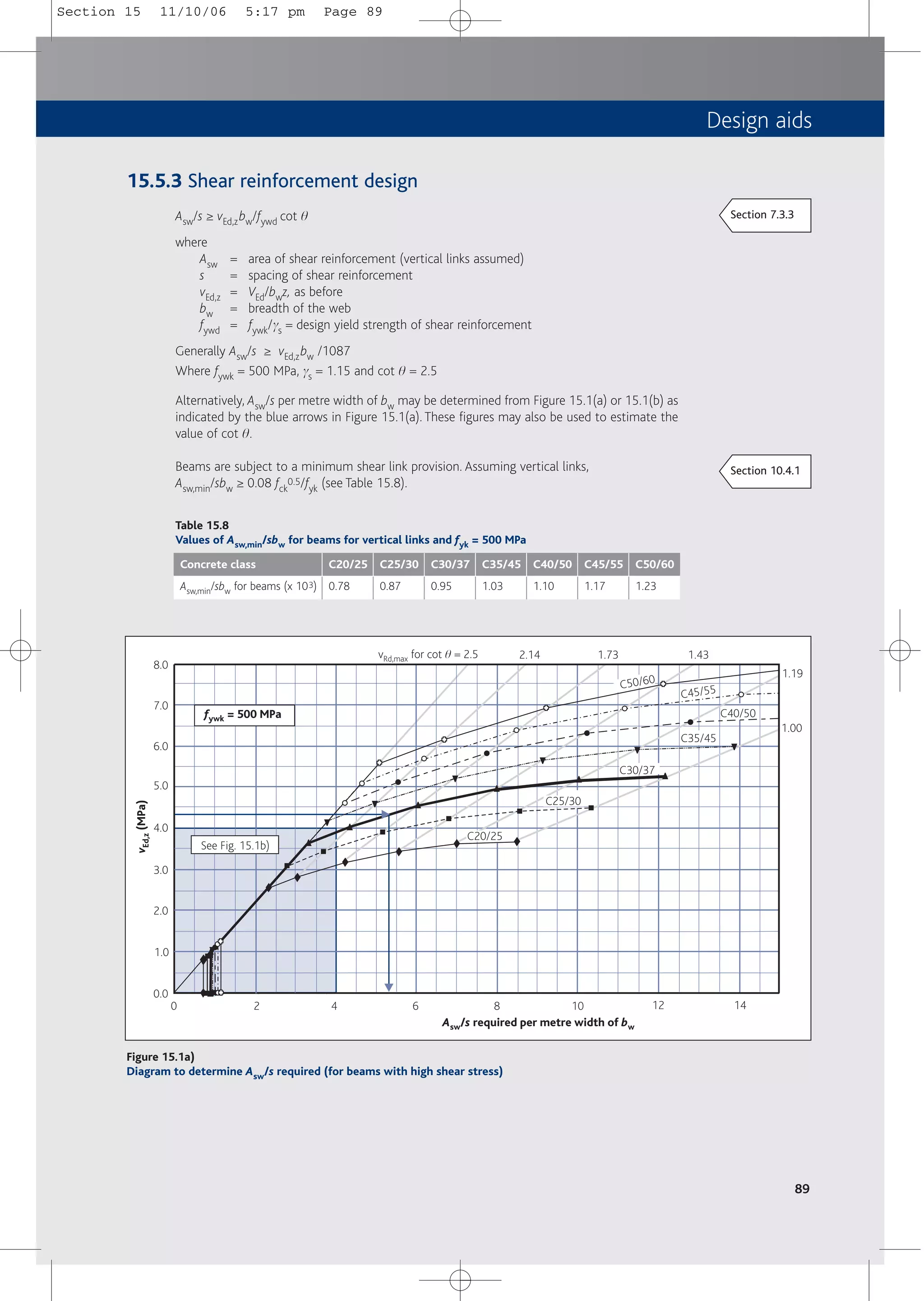
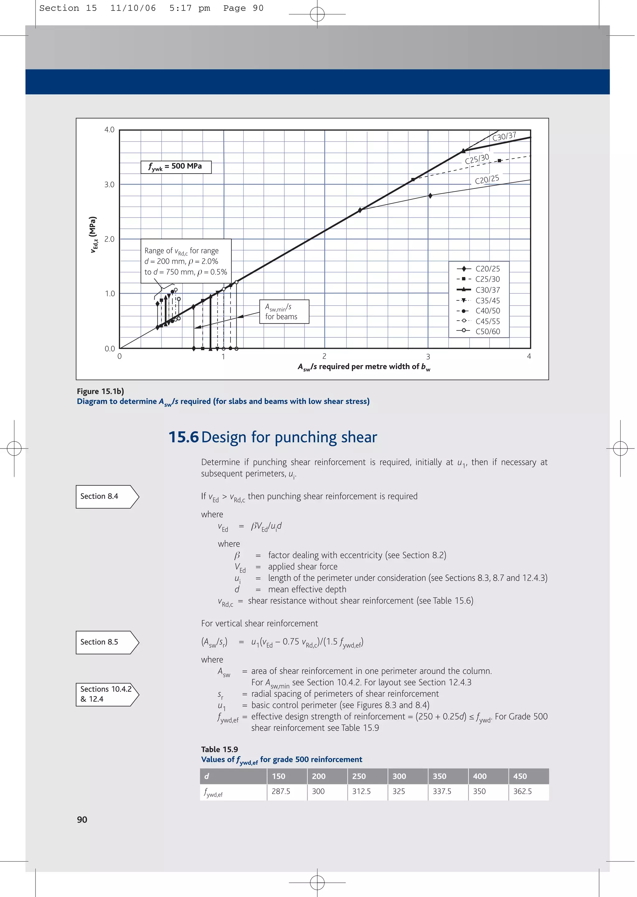
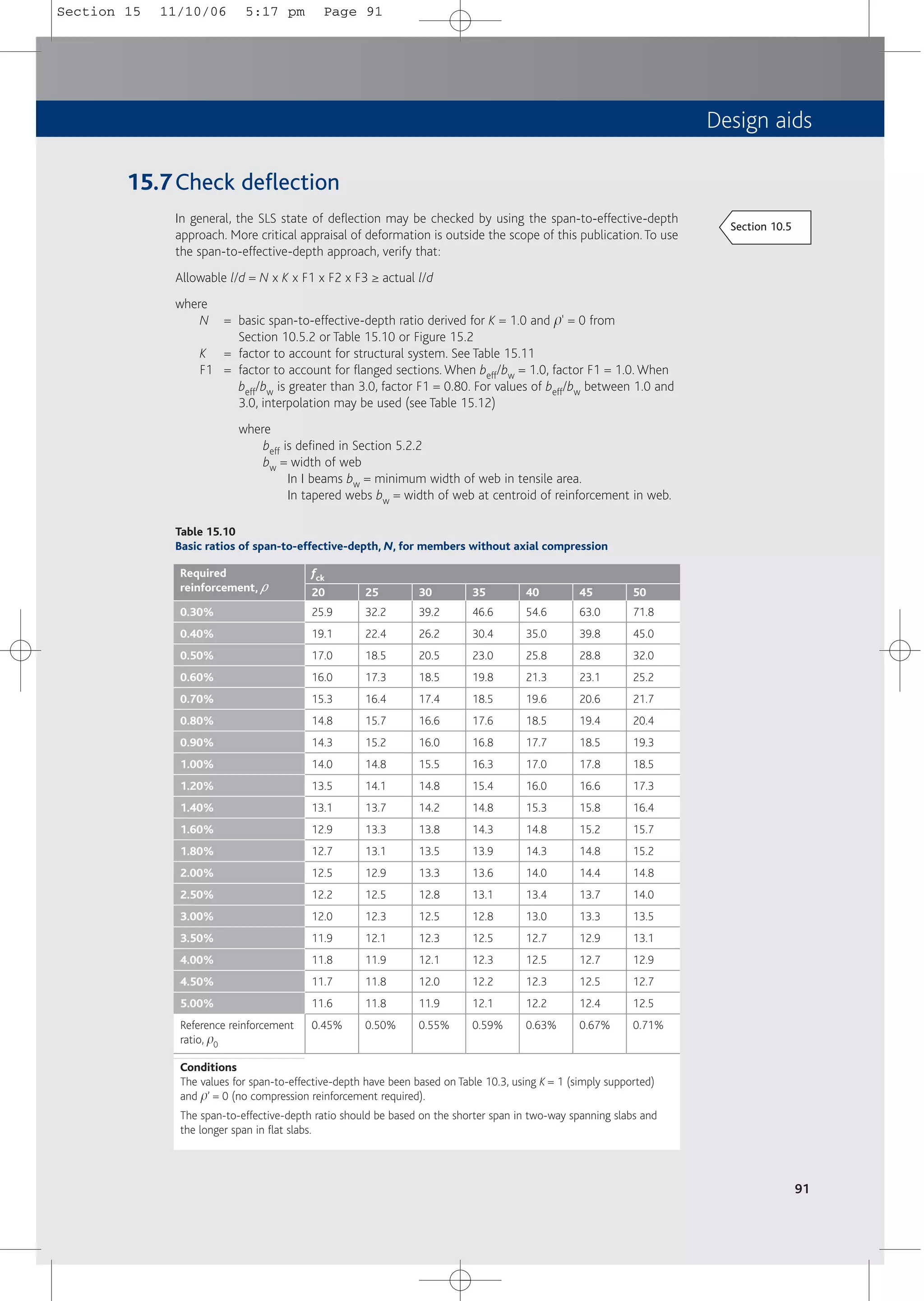
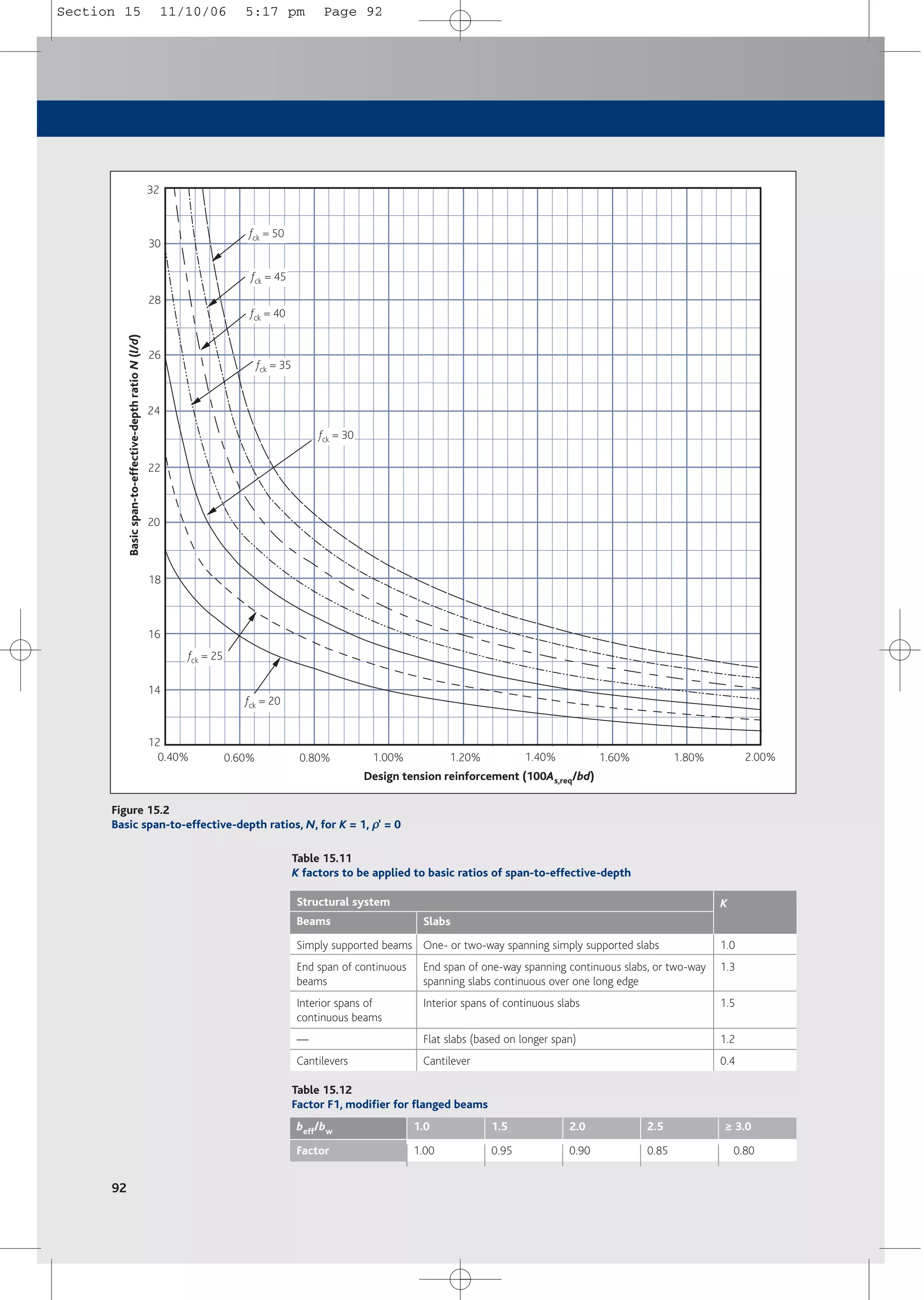
![Design aids
93
Table 15.13
Factor F2, modifier for long spans supporting brittle partitions
Span, m
Flat slabs
Beams and other slabs
leff
8.5/leff
7.0/leff
≤ 7.0
1.00
1.00
7.5
1.00
0.93
8.0
1.00
0.88
8.5
1.00
0.82
9.0
0.94
0.78
10.0
0.85
0.70
11.0
0.77
0.64
12.0
0.71
0.58
13.0
0.65
0.54
14.0
0.61
0.50
15.0
0.57
0.47
16.0
0.53
0.44
F2 = factor to account for brittle partitions in association with long spans. Generally
F2 = 1.0 but if brittle partitions are liable to be damaged by excessive deflection,
F2 should be determined as follows:
a) in flat slabs in which the longer span is greater than 8.5 m, F2 = 8.5/leff
b) in beams and other slabs with spans in excess of 7.0 m, F2 = 7.0/leff
Values of F2 may be taken from Table 15.13
F3 = factor to account for service stress in tensile reinforcement = 310/ss ≤ 1.5
Conservatively, if a service stress, ss, of 310 MPa is assumed for the designed area
of reinforcement, As,req then F3 = As,prov/As,req ≤ 1.5.
More accurately, the serviceability stress, ss, may be calculated from SLS
moments or may be estimated as follows:
ss = fyk/gs[(Gk + y2 Qk)/(1.25Gk + 1.5Qk)] [As,req/As,prov] (1/d)
or
ss = ssu [As,req/As,prov] (1/d)
where
ssu = the unmodified SLS steel stress, taking account of gM for
reinforcement and of going from ultimate actions to
serviceability actions
= 500/gs(Gk + y2Qk)/(1.25Gk + 1.5Qk)
ssu may be estimated from Figure 15.3 as indicated by
the blue arrow
As,req /As,prov = area of steel required divided by area of steel provided.
(1/d) = factor to ‘un-redistribute’ ULS moments so they may be
used in this SLS verification (see Table 15.14)
Actual l/d = actual span divided by effective depth, d.
Table 15.14
(1/δ
δ) factor to be applied to unmodified σ
σsu to allow for redistribution used
Average redistribution used
Redistribution ratio used, δ
δ
(1/δ
δ)
20%
1.20
83%
15%
1.15
87%
10%
1.10
91%
5%
1.05
95%
0%
1.00
100%
–5%
0.95
105%
–10%
0.90
111%
–15%
0.85
118%
–20%
0.80
125%
–25%
0.75
133%
–30%
0.70
143%
Notes
Where coefficients from Table 15.2 have been used in design and where Qk ~ 1.25Gk, the coefficients in Table 15.2 may be considered to
represent moment distribution of:
a) – 8% near middle of end span with pinned end support
b) – 22% at first interior support, as a worst case
c) + 3% near middle of internal spans, as a worst case
d) – 28% at interior supports, as a worst case.
Where coefficients from Table 15.3 have been used in design and where Qk ~ Gk, the coefficients in Table 15.3 may be considered to represent
moment redistribution of:
a) + 3% near middle of end span with pinned end support, as a worst case
b) + 9% near middle of internal spans, as a worst case
c) – 15% at all interior supports.
Section 15 11/10/06 5:17 pm Page 93](https://image.slidesharecdn.com/conciseeurocode2-220718034157-f2f98aab/75/Concise_Eurocode_2-pdf-103-2048.jpg)
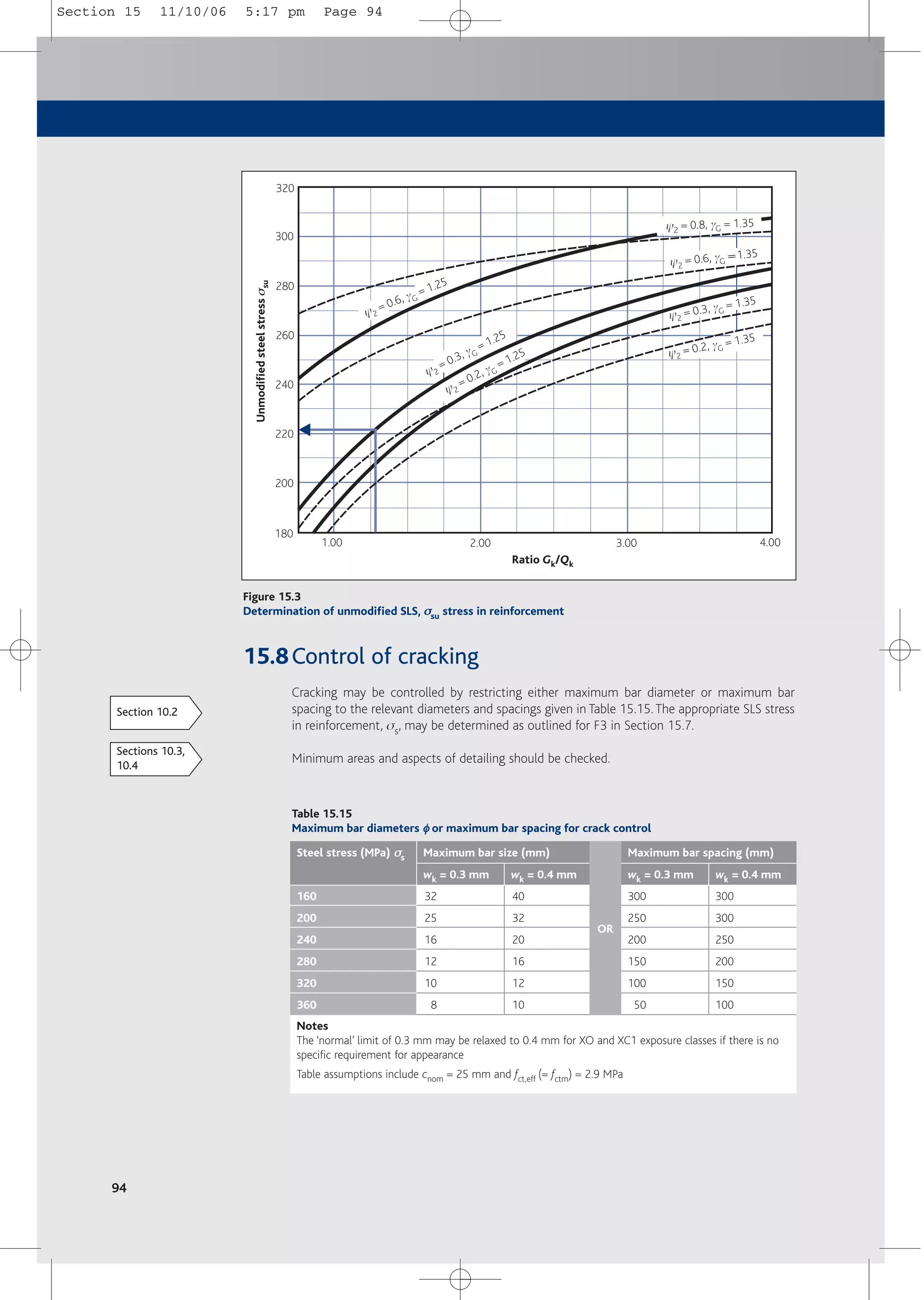
![Design aids
95
15.9Design for axial load and bending
15.9.1 General
In columns, design moments MEd and design applied axial force NEd should be derived from
analysis, consideration of imperfections and, where necessary, 2nd order effects (see Section 5.6).
15.9.2 Design by calculation
Assuming two layers of reinforcement, As1 and As2, the total area of steel required in a column,
As, may be calculated as shown below.
■ For axial load
AsN/2 = (NEd – acchfckbdc /gc)/(ssc – sst)
where
AsN = total area of reinforcement required to resist axial load using this method.
AsN = As1 + As2 and As1 = As2
where
As1(As2) = area of reinforcement in layer 1 (layer 2) (see Figure 6.3)
NEd = design applied axial force
acc = 0.85
h = 1 for ≤ C50/60
b = breadth of section
dc = effective depth of concrete in compression = lx ≤ h (see Figure 6.4)
where
l = 0.8 for ≤ C50/60
x = depth to neutral axis
h = height of section
ssc, (sst) = stress in compression (and tension) reinforcement
■ For moment
AsM/2 = [MEd – acchfckbdc(h/2 – dc/2)/gc]/[(h/2 – d2)(ssc + sst)
where
AsM = total area of reinforcement required to resist moment using this method
AsM = As1 + As2 and As1 = As2
Where reinforcement is not concentrated in the corners, a conservative approach is to calculate
an effective value of d2 as illustrated in Figure 15.4.
■ Solution: iterate x such that AsN = AsM
Section 6.2.2
Section 5.6
Section 15 11/10/06 5:17 pm Page 95](https://image.slidesharecdn.com/conciseeurocode2-220718034157-f2f98aab/75/Concise_Eurocode_2-pdf-105-2048.jpg)
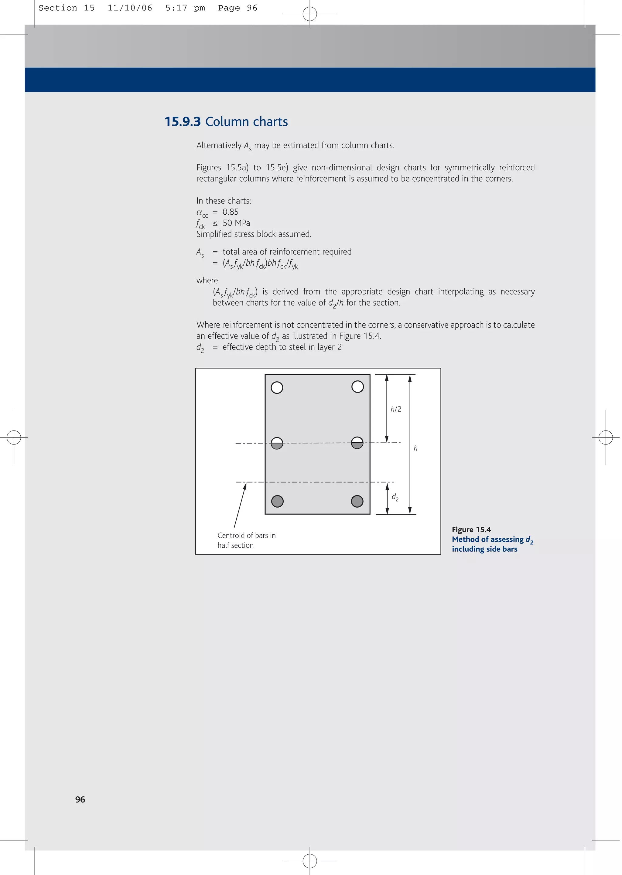
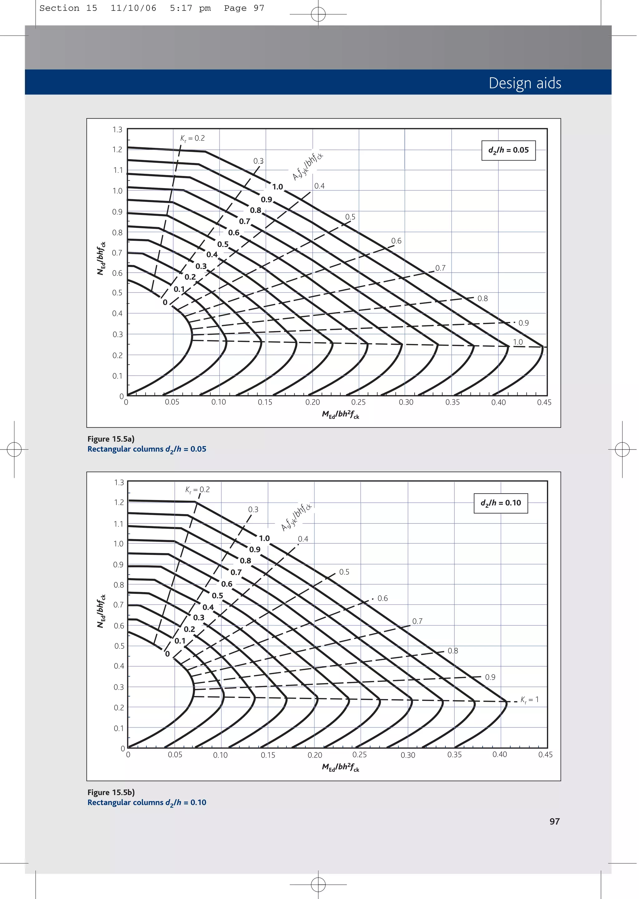
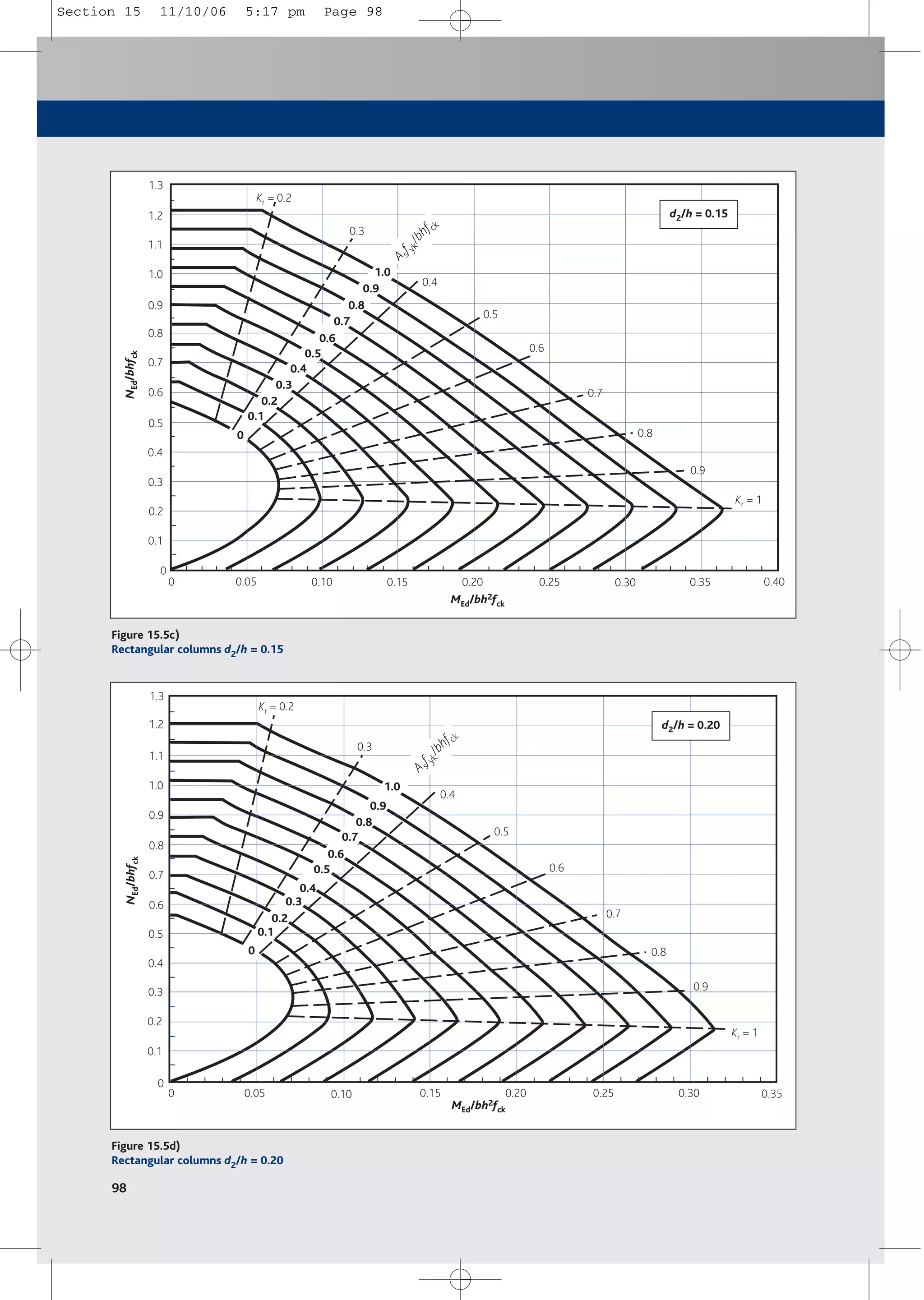
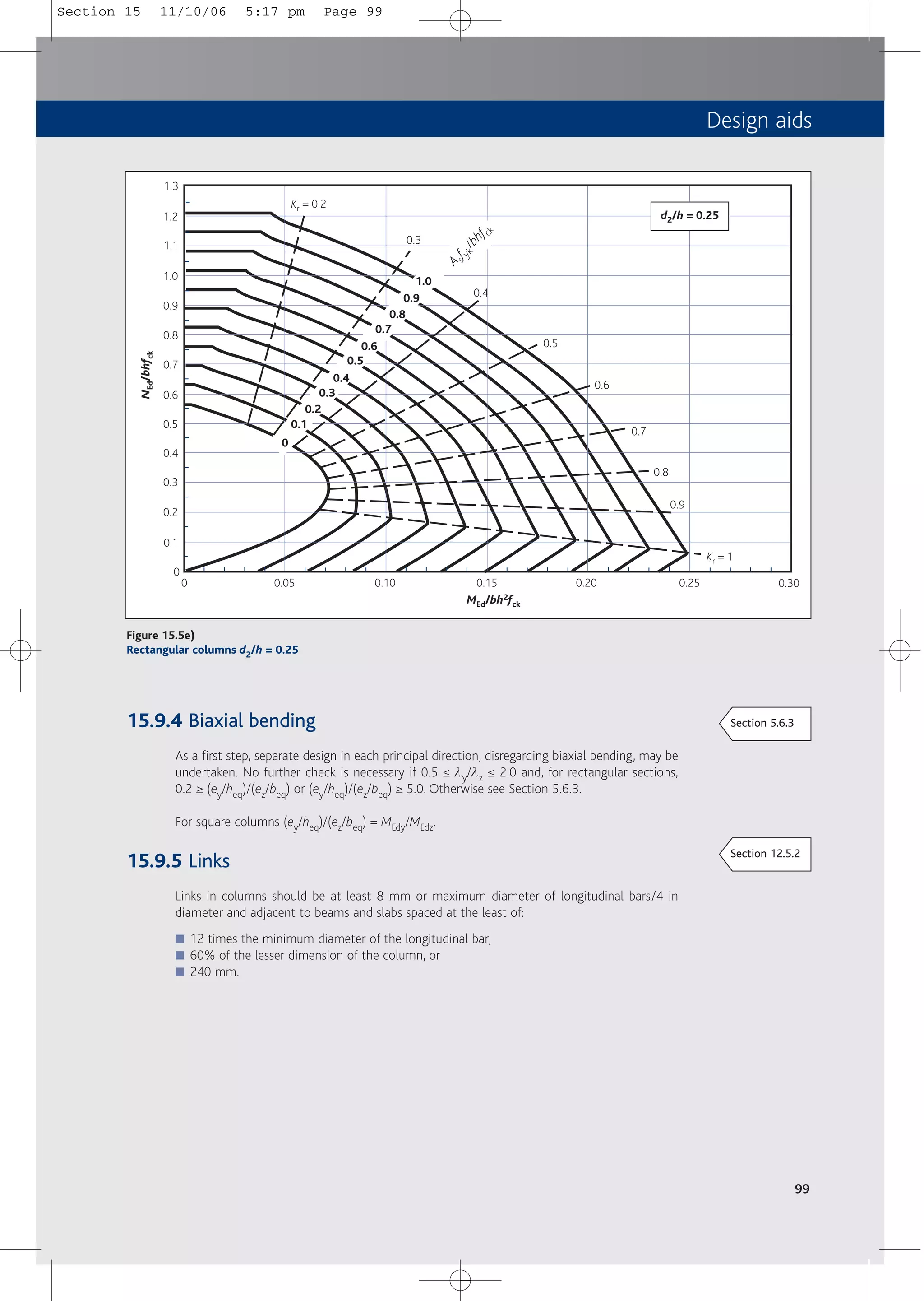
![102
Appendix: simple foundations
A1 General
This appendix is intended to give guidance on the application of Eurocode 7 Part 1[11] to the
design of simple concrete foundations. It will be subject to the provisions of the as yet
unpublished UK National Annex to Eurocode 7. It is recommended that further guidance is
sought from other publications. These include Eurocode 7, a Commentary[29] and Designers’
guide to EN 1997-1[30].
Eurocode 7 is wide-ranging and provides in outline all the requirements for the design of
geotechnical structures, including:
■ Approaches to geotechnical design.
■ Ground investigation.
■ Design aspects of construction.
■ Design of specific elements.
It classifies structures and risks into three categories.
■ Geotechnical Category 1 is for small, relatively simple structures with negligible risk.
■ Geotechnical Category 2 is for conventional structures with no exceptional risk, e.g. spread,
raft and pile foundations, retaining structures, bridge piers and abutments, embankments,
and earthworks and tunnels.
■ Geotechnical Category 3 is for very large or unusual structures or exceptionally difficult
ground conditions and is outside the scope of Eurocode 7.
Eurocode 7 and this appendix concentrate on Geotechnical Category 2.
A2 Actions
In Eurocode 7, design values of actions, Fd, are based on representative actions, Frep.
Fd = gF Frep
where
gF = partial factor for action. See Table A1
Frep = yFk
where
y = factor to convert characteristic actions to representative actions as per BS EN
1990[5] (see Tables 2.1 and 2.2)
Fk = characteristic value of an action
It is anticipated that the structural designer will specify representative actions to the
geotechnical designer.
(The traditional practice of specifying and designing foundations using characteristic actions
may be used by agreement. See A4.2, Prescriptive measures, below.)
BS EN 1997:
1.1.2
BS EN 1997:
2.4.6.1
BS EN 1997:
Exp. (2.1b)
BS EN 1997:
2.1
Concise Appendix 11/10/06 5:18 pm Page 102](https://image.slidesharecdn.com/conciseeurocode2-220718034157-f2f98aab/75/Concise_Eurocode_2-pdf-112-2048.jpg)
![Appendix: simple foundations
A3 Methods of geotechnical design
Eurocode 7 states that no limit state e.g. stability (EQU, UPL or HYD), strength (STR or GEO)
or serviceability, as defined by BS EN 1990[5], shall be exceeded. The requirements for ultimate
and serviceability limit state (ULS and SLS) design may be accomplished by using, in an
appropriate manner, the following alone or in combination.
■ Calculations.
■ Prescriptive measures.
■ Testing.
■ An observational method.
A3.1 Calculations
A3.1.1 Ultimate limit state (ULS)
It is necessary to verify that Ed ≤ Rd
where
Ed = design value of the effect of actions
Rd = design value of the resistance to an action
There are three design approaches in Eurocode 7; the UK is due to adopt design approach 1
(DA1). DA1 requires the consideration of two combinations of partial factors for actions and for
soil parameters to compare ultimate loads with ultimate soil resistance.These combinations are
illustrated in Figure A1. The appropriate partial factors are given in Table A1.
103
BS EN 1997:
2.1(4)
BS EN 1990:
3.5
BS EN 1997:
2.4
BS EN 1997:
2.4.7.3.1
BS EN 1997:
2.4.7.3.4
BS EN 1990:
A1.3.1(5)
& NA
Table A1
Partial factors for design approach 1 (for STR/GEO excluding piles and anchorages)
Combination Partial factor on actions, γ
γF Partial factors for soil parameters, γ
γM
Combination 1a
Combination 2b
γ
γG
c
1.35 (1.0*)
1.0 (1.0*)
γ
γG
c
1.5 (0.0*)
1.3 (0.0*)
γ
γϕ
ϕ'
c
1.0
1.25
γ
γc'
c
1.0
1.25
γ
γcu
c
1.0
1.4
Key
* = value if favourable
G = permanent action
Q = variable action
j’ = angle of shearing resistance (in terms of effective stress)
c’ = cohesion intercept (in terms of effective stress)
cu = undrained shear strength
a = Combination 1 partial factors on actions equate to Set B loads (BS EN 1990[5] Table NA.A1.2(B))
NB: the use of Expressions (6.10a) and (6.10b) was not anticipated within Eurocode 7.
b = Combination 2 partial factors on actions equate to Set C loads (BS EN 1990 Table NA.A1.2(C))
c = the factor gj' is applied to tan j'
BS EN 1997:
Table A.3
BS EN 1997:
Table A.4
Concise Appendix 11/10/06 5:18 pm Page 103](https://image.slidesharecdn.com/conciseeurocode2-220718034157-f2f98aab/75/Concise_Eurocode_2-pdf-113-2048.jpg)
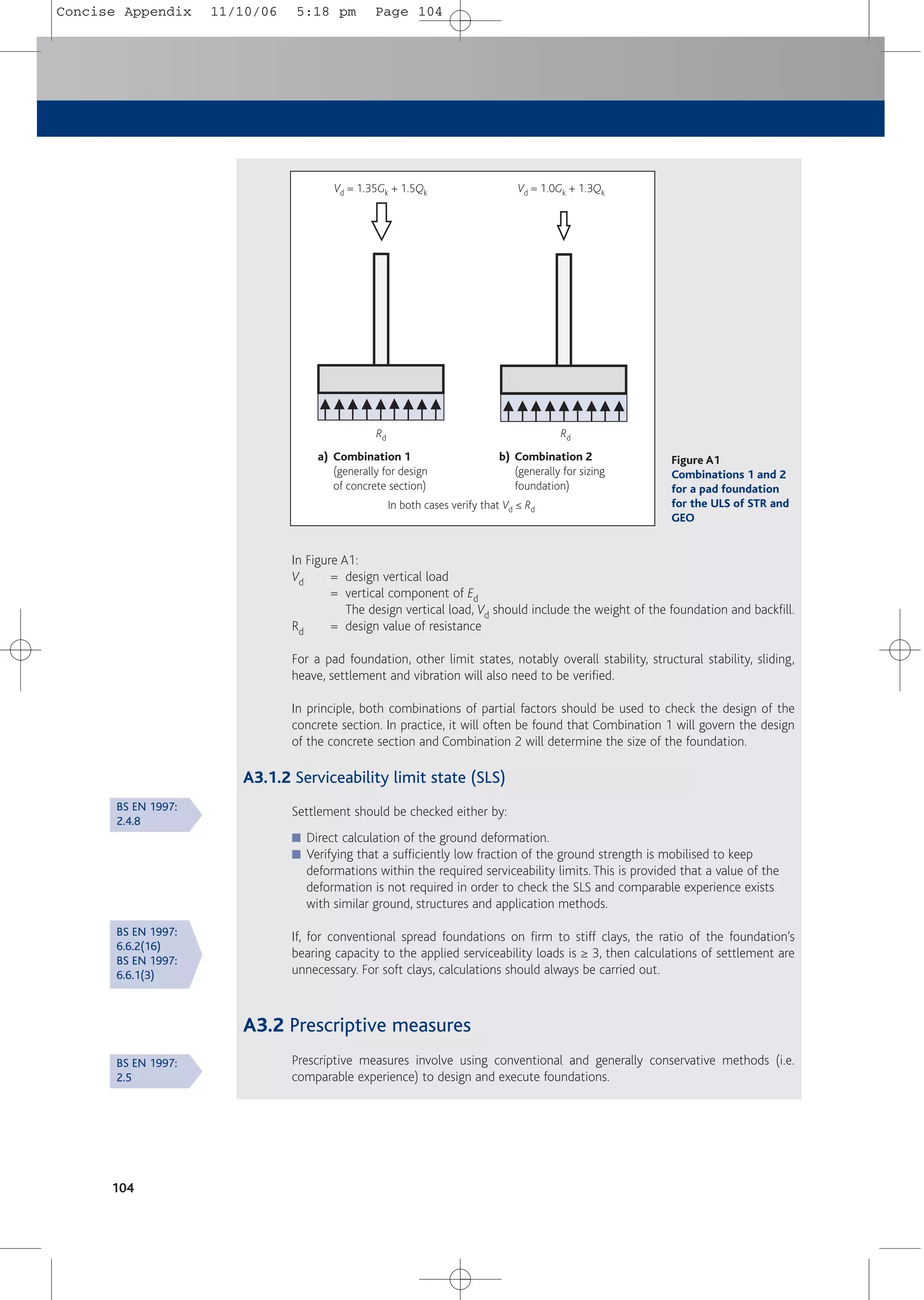
![Appendix: simple foundations
105
A3.3 Testing
The results from testing (e.g. from load tests on piles or ground anchors) or modelling (provided
the effects of ground variations, time and scale are considered) may be used in place of, or in
combination with, calculations.
A3.4 Observational method
The observational method relates mainly to temporary works where performance is observed
and responses can be made to the results of monitoring.
A4 Geotechnical design of spread foundations
The size of spread foundations may be determined by one of the following methods:
■ Calculations.
■ By using a prescribed method such as using local practice.
■ Using calculated allowable bearing pressures.
A4.1 Calculations
A4.1.1 Ultimate limit state (ULS)
Spread foundations shall be checked for ultimate limit states of overall stability, bearing
resistance and sliding.The bearing resistance of the ground shall be determined for both short-
term (i.e. undrained) and long-term (i.e. drained) conditions where applicable.
A4.1.1.1 Undrained conditions
The design bearing resistance of cohesive soils in undrained conditions depends on:
■ Soil’s undrained strength (cu).
■ Vertical total stress at foundation level (q).
■ Shape (B/L) and inclination (a) of the foundation.
■ Any inclination and/or eccentricity (e) of the load.
The vertical bearing resistance per unit area
R/A' = function of [cu, q, B/L, a, e, H]
where
R = vertical bearing resistance
A' = effective area of the base
H = horizontal load
The design undrained bearing resistance must be calculated for both combinations of partial
factors given in Table A1.
A4.1.1.2 Drained conditions
The design bearing resistance of both granular and cohesive soils in drained conditions depends on:
■ Soil’s weight density (i.e. unit weight, g).
■ Effective cohesion (c').
■ Angle of shearing resistance (j').
■ Weight density of water (gw).
■ Vertical effective stress at foundation level (q').
BS EN 1997:
6.4(5)
BS EN 1997:
2.6
BS EN 1997:
2.7
BS EN 1997:
6.5.1
BS EN 1997:
2.2(1)
BS EN 1997:
6.5.2.2.(1)
BS EN 1997:
D3
BS EN 1997:
6.5.2.2.(1)
BS EN 1997:
D4
Concise Appendix 11/10/06 5:18 pm Page 105](https://image.slidesharecdn.com/conciseeurocode2-220718034157-f2f98aab/75/Concise_Eurocode_2-pdf-115-2048.jpg)
![106
■ Shape (B/L).
■ Inclination (a) of the foundation.
■ Any inclination and/or eccentricity (e) of the load.
(It should be noted that the bearing capacity factors that are used to determine drained bearing
resistance are particularly sensitive to the angle of shearing resistance of the soil.)
The vertical bearing resistance per unit area
R/A' = function of [g, c', j', gw, q', B/L, a, e, H] where the symbols are as defined above for
drained bearing resistance.
The design undrained bearing resistance must be calculated for both combinations of partial
factors given in Table A1.
A4.1.1.3 Bearing resistances
It is anticipated that values of ULS design vertical bearing resistance, R/A', will be made available
to structural designers in the‘Geotechnical design report’ for a project, which itself will be based
on the ‘Ground investigation report’. Usually, it will be found that, with respect to sizing the
foundation, Combination 2 (see Table A1) will be critical.
For eccentric loading at ULS, it is assumed that the resistance of the ground is uniformly
distributed and is centred on the centre of gravity of the applied load. For a base L x B with load
eccentricities ex and ey,
A' = (B – 2ex)(L – 2ey) (see Figure A2)
Sliding resistance should be checked in a similar manner.
A4.1.2 Serviceability limit state (SLS)
A4.1.2.1 Settlement
For the serviceability limit state, settlement should be checked by calculation or may, in the
case of spread foundations on clays, be assumed to be satisfactory if the ratio of the
foundation’s ULS bearing capacity to the applied serviceability loads (with gG = 1.0, gQ = 1.0
and y2 as appropriate) is ≥ 3. This approach is not valid for very soft soils so settlement
calculations shall always be carried out for soft clays.
Pressure distribution
b) Plan
a) Elevation
M
CG load
CG base
+
2ey
B – 2ex 2ex
L – 2ey
ex
ey
Vd
Figure A2
Effective area for eccentric loading at ULS
BS EN 1997:
D4
BS EN 1990:
A1.3(5)
BS EN 1997:
6.6
Concise Appendix 11/10/06 5:18 pm Page 106](https://image.slidesharecdn.com/conciseeurocode2-220718034157-f2f98aab/75/Concise_Eurocode_2-pdf-116-2048.jpg)
![Appendix: simple foundations
A4.1.2.2 Serviceability
Serviceability checks should be made against the Serviceability Limit State design loads. For
most building structures, this would be the quasi-permanent load case (see Table 2.1d).
A4.1.3 Communications
As described in A2 above, it is anticipated that the ‘currency of exchange’ will be representative
actions. However, in communications, it will be vital to define:
■ Loads as being Combination 1, Combination 2, characteristic or more usefully,
representative values of the permanent and variable actions; and
■ Applicability of values of R/A' (whether to Combination 1 or Combination 2 at ULS, SLS,
and with respect to shape of foundation, inclination of loads, etc).
A4.2 Prescriptive measures
The practice of checking characteristic actions (gG = 1.0, gQ = 1.0) against allowable bearing
pressures may be adopted within the requirements of Eurocode 7, in one of two ways, viz:
■ Local practice.
■ Calculated allowable bearing pressures.
A4.2.1 Local practice
The allowable bearing pressures may be regarded as ‘Prescriptive measures’, which “may be used
where comparable experience … makes [geotechnical] design calculations unnecessary”. Such
allowable bearing pressures could be specified by local Building Control authorities or on the
basis of well established local practice such as BS 8004 Foundations[31].
A4.2.2 Calculated allowable bearing pressures
Alternatively, the writer of the site/ground investigation report could be required to calculate
and/or specify allowable bearing pressures which provide designs consistent with both the ULS
and SLS requirements of Eurocode 7. However, this may require knowledge of the size of the
loads and, in particular, any eccentricity or inclination of loads.
A5 Piled foundations
The allowable methods for the geotechnical design of piles include:
■ Static load tests (shown to be consistent with calculations or other relevant experience).
■ Calculations (validated by static load tests).
Structural design of piles and pile caps should be carried out to Eurocode 2.
A6 Retaining walls and other forms of foundation
The sizing and design of retaining walls and other forms of foundation are outside the scope of
this publication. For these and/or where the foundations are unconventional or the risks
abnormal, specialist literature should be consulted and guidance sought.
107
BS EN 1997:
2.5
BS EN 1997:
2.5(2)
BS EN 1997:
7.4.1
Concise Appendix 11/10/06 5:18 pm Page 107](https://image.slidesharecdn.com/conciseeurocode2-220718034157-f2f98aab/75/Concise_Eurocode_2-pdf-117-2048.jpg)

This document provides a concise summary of Eurocode 2 (EC2) for the design of reinforced concrete framed buildings. It aims to guide readers through the key aspects of EC2 and other relevant Eurocodes. The publication covers topics such as basis of design, materials, durability, structural analysis, bending and axial load, shear, punching shear, torsion, serviceability, detailing requirements, and design aids. It is intended to help designers transition to designing according to EC2 and the UK National Annex.